GENERATOR DIESEL ENGINE DP158LCF/LCS/LDF/LDS, DP180LBS/LAS/LBF/LAF, DP222LAS/LBF/LBS/LCF/LCS. Maintenance Manual - page 3
5. About the engine
98
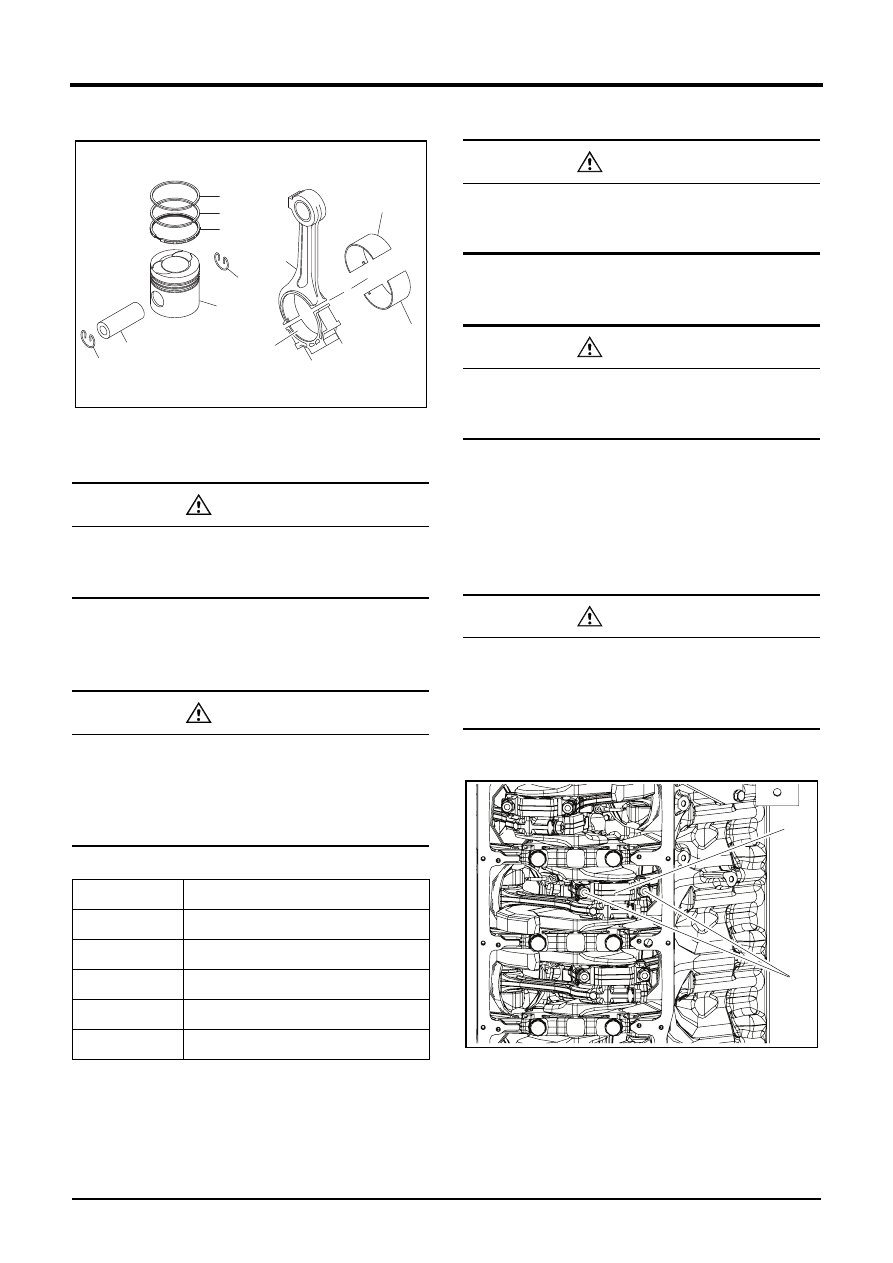
12. Attach the piston to the connecting rod.
DV2213177A
1) Install the 1st ring(D), 2nd ring(E), and the oil ring(F)
with the piston ring plier(T7621010E).
2) Apply engine oil on the piston pin(C).
3) Align the pin hole of the connecing rod(G) small-end
with that of the piston(A).
4) Attach the piston pin(C).
5) Attach 2 snap rings(B) with the snap ring plier
(T7610001E).
6) Align the upper bearing groove with connencting rod.
Attacht the upper connecting rod bearing(I) to the
connecting rod(G).
7) Align the lower bearing groove with connecting rod.
Attach the lower connecting rod bearing(J) to the
connecting rod bearing cap(H).
13. Attach the connecting rod and piston assembly.
DV2213088A
1) Attach the connecting rod and piston assembly to the
cylinder block.
2) Attach the connecting rod cap(B).
3) Tighten 2 M16X1 flange hex bolts(A) at a tightening
torque 10 kgf
·
m + 90
°
by using the angle method.
CAUTION
•
Ensure that the ‘Y’ mark of the piston ring faces
the top surface of the piston.
•
Make the piston ring position dislocated to 120
°
CAUTION
•
The intake valve pocket is larger than the exhaust
valve pocket.
•
Attach the engine as the same piston weight.
Place the Class of the piston weight on the top
surface of the piston.
CLASS
Piston Weight(g)
A
2,371 ~ 2,380
B
2,381 ~ 2,390
C
2,391 ~ 2,400
D
2,401 ~ 2,410
E
2,411 ~ 2,420
J
I
D
E
B
A
F
B
C
H
G
CAUTION
Check the attached piston and piston ring. If the
piston should be replaced, replace the piston pin
along with the piston.
CAUTION
•
Do not reuse the snap rings.
•
Assemble snap rings with the opening of the
snap rings facing 12 o’clock.
CAUTION
•
Be careful the direction when assembling the
connecting rods and the connecting rod caps.
•
Ensure that the marks of the connecting rod and
the bearing cap are facing the same direction.
A
B
5. About the engine
99
4) Attach 12 connecting rod and piston assembly as the
same procedure.
14. Attach the oil suction pipe and the oil pump.
DV2213087A
1) Attach the oil suction pipe and the oil pump(D).
2) Tighten M8 fixing bolt(C) at a tightening torque 2.2
kgf
·
m.
3) Tighten 2 M8 fixing bolts(B) at a tightening torque 2.2
kgf
·
m.
4) Tighten 2 M8 fixing bolt(A) at a tightening torque 2.2
kgf
·
m.
15. Attach the oil pan.
DV2213086A
1) Attach the oil pan(B).
2) Tighten 20 M8 fixing bolts(A) at a tightening torque
2.2 kgf•m ± 0.33kgf•m.
16. Change the engine position.
DV2213185A
1) Change the engine positon. The piston direction is
upward.
17. Adjust the fuel injection timing.
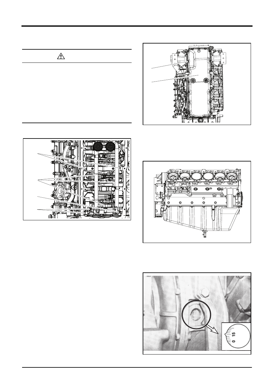
DV2213027A
CAUTION
•
Be careful to note the direction when attaching
the connecting rods and the connecting rod caps.
Ensure that the number engraved on the
connecting rods is same with that engraved on
the connecting rod caps and the assembly direc-
tion is same.
•
Attacht the connecting rod and piston assembly
without contacting the crankshaft weight. Rotate
the crankshaft.
A
B
C
D
A
B