GENERATOR DIESEL ENGINE DP158LCF/LCS/LDF/LDS, DP180LBS/LAS/LBF/LAF, DP222LAS/LBF/LBS/LCF/LCS. Maintenance Manual - page 2
 

  Index      Manuals     GENERATOR DIESEL ENGINE DP158LCF/LCS/LDF/LDS, DP180LBS/LAS/LBF/LAF, DP222LAS/LBF/LBS/LCF/LCS. Maintenance Manual


Search            copyright infringement  


Content      ..      1      2      3      ..


GENERATOR DIESEL ENGINE DP158LCF/LCS/LDF/LDS, DP180LBS/LAS/LBF/LAF, DP222LAS/LBF/LBS/LCF/LCS. Maintenance Manual - page 2


4. Regular inspection

 64

Cylinder block/head

Valve Clearance

Adjust the valve clearance.

When disassembling the engine or cylinder head.

When there is excessive noise in the valve connec-

tion.

When the engine runs abnormally even if the fuel

injection system is normal.

Adjusting the Valve Clearance

DV2213041A

DV2213042A

DV2213213A

DV2213043A

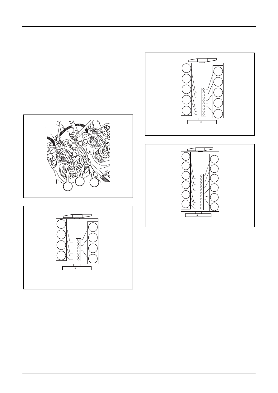
1. Rotate the crankshaft so that #1. cylinder may be

positioned at the compression TDC(Top Dead Center).

Note) #1. Cylinder is located at the side where cooling 

water pump was installed.

Note) In case of 8/12 cylinder engine, #6. cylinder is posi-

tioned at the valve overlap when #1. cylinder is 

positioned at the compression TDC(Top Dead 

Center).

Note) In case of 10 cylinder engine, #7. cylinder is posi-

tioned at the valve overlap when #1. cylinder is 

positoned at the compression TDC(Top Dead 

center).

2. Loosen the lock nut of the #1. cylinder rocker arm.

3. Push the feeler gauge between a rocker arm and a

valve stem.

4. Adjust the clearance screw respectively and then

tighten with the lock nut.

5. As for the valve clearance, adjust it when in cold, as

follows.

1

2

3

5

6

7

8

1

2

3

4


8


7


6


5


4


3


2


1

8

 Cy

lin

d

er


engine

6

7

8

9

10

1

2

3

4

5

10

  9
  8
  7
  6
  5
  4
  3
  2
  1

10 

Cy

lin

d

er engine

7

8

9

10

11

12

1

2

3

4

5

6

12
11
10

  9
  8
  7
  6

  5
  4
  3
  2
  1

12 

Cy

lin

d

er engine

4. Regular inspection

 65

6. Rotate the crankshaft. When a cylinder reaches the

compression TDC(Top Dead Center), adjust the valve

clearance of the cylinder.

7. When a cylinder vavle overlap, adjust the valve clear-

ance cylinder of the compression TDC(Top Dead

Center), as follow.

8 cylinder engine(DP158L)

10 cylinder engine(DP180L)

12cyliner engine(DP222L)

Tightening Cylinder Head Bolt

1. Retightening cylinder head bodt on new engine.

DV2213044A_E

1) The cylinder heads are mounted with cylinder head

bolts which are tightened by the angle-ofrotation

method.

2) On new engines the cylinder head bolts are tightened

up for the first time at the factory after the engine has

been broken in.

3) After the first 400 hours of operation retighten cylinder

head bolts 1 to 4 in the order shown in right figure

by a further 90°(1/4 revolution).

Engine Model

In. valve

Ex. valve

DP158L

DP158LCS

0.25mm

0.35mm

DP158LCF

0.25mm

0.35mm

DP158LDS

0.25mm

0.35mm

DP158LDF

0.25mm

0.35mm

DP180L

DP180LBS

0.25mm

0.35mm

DP180LBF

0.25mm

0.35mm

DP180LAS

0.25mm

0.35mm

DP180LAF

0.25mm

0.35mm

DP222L

DP222LAS

0.25mm

0.35mm

DP222LBS

0.25mm

0.35mm

DP222LBF

0.25mm

0.35mm

DP222LCS

0.25mm

0.35mm

DP222LCF

0.25mm

0.35mm

Valve overlap cylinder No.

1

5

7

2

6

3

4

8

6

3

4

8

1

5

7

2

Adjusting valve cylinder No. (In./Ex. Valve)

Valve overlap cylinder No.

1

6

5

10

2

7

3

8

4

9

7

3

8

4

9

1

6

5

10

2

Adjusting valve cylinder No. (In./Ex. Valve)

Valve overlap cylinder No.

1

12

5

8

3

10

6

7

2

11

4

9

6

7

2

11

4

9

1

12

5

8

3

10

Adjusting valve cylinder No. (In./Ex. Valve)

CAUTION

The two outer screws (intake and exhaust sides)

must not be retightened.

The cylinder head bolts to be retightened must

not be loosened first, but simply tightened by a

further 90°(1/4 revolution) from their actual posi-

tion.

1

Intake si

d

e injector

Exhaust si

d

e

4

3

2

4. Regular inspection

 66

2. Tightening cylinder head bolts after a repair. (Engine

cold)

DV2213045A_E

1) Tighten temporarily 1~2 threads by hands.

2) 1st step: Tighten to about 8kgf•m with a wrench.

3) 2nd step: Tighten to about 15kgf•m with a wrench.

4) 3rd step: Rotate 90° with a wrench.

5) Final step: Rotate 90° with a wrench.

6) After the first 10 to 20 hours of operation after a repair

turn the cylinder head bolts by a further 90°(1/4 revo-

lution).

7) After 400 hours of operation turn the cylinder head

bolts by a further 90°(1/4 revolution).

Cylinder Compression Pressure

1. Start and warm up the engine.

2. Stop the engine and disassemble the fuel injection

nozzle holder assembly.

3. Install a special tool, compression pressure gauge

adapter (EU.2-0532), in the fuel injection nozzle holder

hole.

DV2213046A

4. Connect the compression pressure gauge to the

adapter.

CAUTION

If excessive torque may damage the cylinder

head gasket, cylinder liner flange and cylinder

head bolt, so keep the specified torque.

When tightening cylinder head bolts after a repair

must always adjust the valve clearance.

CAUTION

The cylinder head bolts to be retightened must not 

bolts loosened first, but simply tightened by a 

further 90°(1/4 revolution) from their actual position.

1

Intake si

d

e injector

Exhaust si

d

e

4

3

5

6

2

CAUTION

The two outside screws (intake and exhaust side)

must not be retightened.

The cylinder head bolts to be retightened must

not be loosened first, but simply tightened by a

further 90°(1/4 revolution) from their actual posi-

tion.

when a cylinder head has been removed the

cylinder head gasket must always be changed.

Standard

Above 28kg/cm

2

Tolerance limit

24kg/cm

2

Difference between each cylinder

Within 

±

10%

4. Regular inspection

 67

Electric system

Battery

Check for the electrolyte leakage by crack in the

battery, and replace the battery if defective.

Check the amount of electrolyte, and replenish distilled

water if insufficient.

Check the specific gravity of electrolyte. If it is below

the specified value (1.12 ~ 1.28), replenish it.

DV2213040A_E

Starter

When servicing the engine, immerse the starter motor’s 

pinion gear and ring gear in the fuel, wash them 

completely, and apply grease again. When you clean the 

surrounding of engine, be careful so that water may not 

enter the starter.

Viewing the

gravit

y

 meter

Liqui

d

 level

in

d

icating line

liqui

d

 level upper limit

liqui

d

 level lower limit

lsotator

UPPER LEVEL
LOWER LEVEL

CAUTION

Starter should be protected from humidity all the

time.

Before working on the electric system, be sure to

disconnect the ground wire (“-” minus wire) of

the battery. Short circuit may occur while working

on the electrical system. Connect the ground wire

last after completing all of work.

4. Regular inspection

 68

Others/driving system

V-Belt

The tension of the V-belts should be checked daily .

1. Change the V-belts if necessary

1) If in the case of a multiple V-belt drive, wear or

differing tensions are found, always replace the

complete set of V-belts.

2. Checking condition

1) Check V-belts for cracks, oil, overheating and wear.

3. Testing by hand

DV2213047A_E

1) For the V-belt tension, when you press the center

between pulleys, if it is pressed by 10~15mm, it is

normal.

2) To check the tension of V-belt more accurately, you

can use a V-belt tension gauge.

4. Tension measurement

1) Lower indicator arm (1) into the scale.

DV2213048A

2) Apply tester to belt at a point midway between two

pulleys so that edge of contact surface (2) is flush

with the V-belt.

DV2213049A

3) Slowly depress pad (3) until the spring can be heard

to disengage. This will cause the indicator (1) to move

upwards.

Note) If pressure is maintained after the spring has disen-

gaged a false reading will be obtained.

4) Read the tension value at the point that the top

surface of indicator arm(1) intersects with the scale.

5) Before taking readings makes ensure that the indicator

arm remains in its position.

Note) If the value measured devotes from the setting 

value specified, the V-belt tension must be 

corrected according to the following table.

Press

C

rankshaf

Alternator

Water 
Pump

10~15mm

1

Type

Belt 

width 

(mm)

Tension from a Tension Meter

New belt (kg)

Replace-

ment 

required

Upon 

installa-

tion

After 10 

minute

M

8.5

50

45

40

A

11.8

55

50

45

B

15.5

75

70

60

C

20.2

75

70

60

3V-2

18.8

90~100

70~80

60

3V-4

39.4

180~200

140~160

120

3V-6

60.0

270~300

210~240

180

3

2

4. Regular inspection

 69

5. Tension adjustment and V-belt replacement

DV2213050B

1) Loosen the fixing bolt(1).

2) Loosen the lock nut(2).

3) Adjust the bolt(3) until belt have correct tension.

4) Tighten the fixing bolt(1) and nut(2).

5) To replace the V-belt, loosen the fixing bolts(1) and

the lock nut(2) and push the tension pulley inwards

by turning the adjusting bolt(3) counter clockwise.

DV2213055A

6) Loosen the mounting bolts(B).

7) Loosen the lock nut(A).

8) Adjust the nut(C) until the belt tension has correct

tensions.

9) Retighten the lock nut(A) and the mounting bolt(B).

10) To replace the belt, loosen the lock nut and push the

alternator inwards.

2

1

1

3

A

B

C

 71

5. About the engine

Marking system of units

 . . . . . . . . . . . . . . . . . . . . . . . . . . . . . . . . . . . . . . . . . . . . . . . . . . 73

Unit Conversion Methods

 . . . . . . . . . . . . . . . . . . . . . . . . . . . . . . . . . . . . . . . . . . . . . . . . . 73

Tightening torque

. . . . . . . . . . . . . . . . . . . . . . . . . . . . . . . . . . . . . . . . . . . . . . . . . . . . . . . . 74

Tightening Torque of Main Parts

. . . . . . . . . . . . . . . . . . . . . . . . . . . . . . . . . . . . . . . . . . . . 74

Tightening Torque of General Bolts

. . . . . . . . . . . . . . . . . . . . . . . . . . . . . . . . . . . . . . . . . . 75

Tightening torque of plug screw

 . . . . . . . . . . . . . . . . . . . . . . . . . . . . . . . . . . . . . . . . . . . . 77

Hollow Screw (4-Hole) Tightening Torque

 . . . . . . . . . . . . . . . . . . . . . . . . . . . . . . . . . . . . . 77

Special tool

 . . . . . . . . . . . . . . . . . . . . . . . . . . . . . . . . . . . . . . . . . . . . . . . . . . . . . . . . . . . . 78

Special Tool

. . . . . . . . . . . . . . . . . . . . . . . . . . . . . . . . . . . . . . . . . . . . . . . . . . . . . . . . . . . 78

Engine Disassembly

. . . . . . . . . . . . . . . . . . . . . . . . . . . . . . . . . . . . . . . . . . . . . . . . . . . . . . 82

Procedure of Disassembling an Engine

. . . . . . . . . . . . . . . . . . . . . . . . . . . . . . . . . . . . . . . 82

Engine Assembly

. . . . . . . . . . . . . . . . . . . . . . . . . . . . . . . . . . . . . . . . . . . . . . . . . . . . . . . . 95

Procedure of Assembling Engine

. . . . . . . . . . . . . . . . . . . . . . . . . . . . . . . . . . . . . . . . . . . . 95

5. About the engine

 73

Marking system of units

Unit Conversion Methods

The following methods show how to convert SI units to 

US units and vice versa.

1. To convert an SI unit to a US unit, multiply a SI unit

with the number in the following table.

Note) (SI Unit) X (Number) = (US Unit)

Note) 1mm X 0.03937 = 0.03937 in

2. To convert a US unit to an SI unit, divide the US unit

by the number in the following table.

Note) (US Unit) ÷ (Number) = (SI Unit)

Note) 1 in ÷ 0.03937 = 25.4 mm

Item

Number

SI Unit

US Unit

Length

0.03937

mm

in

3.28084

m

ft

1.093613

m

yd

0.621371

km

mile

Area

0.00155

mm

2

in

2

0.1550

cm

2

in

2

10.76391

m

2

ft

2

1.19599

m

2

yd

2

Weight

2.204623

kg

lb

0.001

kg

t (ton)

Volume

0.061024

cc

in

3

0.061024

ml

in

3

0.061024

cm

3

in

3

61.023744

L

in

3

0.264172

L

gal

Force

a

2.204622

kgf

lbf

0.2248089

N

lbf

Acceleration

3.28084

m/s

2

ft/s

2

39.37008

m/s

2

in/s

2

Torque

b

7.233014

kgf

·

m

ibf

·

ft

86.79619

kgf

·

m

ibf

·

in

0.7375621

N

·

m

ibf

·

ft

8.850748

N

·

m

ibf

·

in

Power

1.340483

kw

Hp

Pressure

0.01

kPa

bar

7.500615

kPa

mmHg

20.88543

kPa

lb/ft

2

14.2233

psi

kg/cm

2

Power

1.3596

kw

PS

0.98635

ps

hp

Fuel Con-
sum ption

0.00162

g/kwh

lb/psh

Energy

0.000947817

J

BTU

0.7375621

J

lbf

·

ft

0.000277778

J

Wh

Luminous 

Flux

0.09290304

lm/m

2

lm/ft

2

Speed

0.6213712

km/h

mph

Temperature

c

°

C

°

F

a. 9.806 x (kgf) = (N)
b. 9.806 x (kgf

·

m) = (N

·

m)

c. {(9/5) x (

°

C) + 32} = (

°

F)

{(

°

F) - 32} x (5/9) = (

°

C)

Item

Number

SI Unit

US Unit

5. About the engine

 74

Tightening torque

Tightening Torque of Main Parts

Main Parts

Nominal

(Diameter x Pitch)

Tensile Strength 

Rank

Tightening Torque

Remarks

Cylinder Block Main 
Bearing Cap Bolt

M18 X 2

12.9T

1st: 30.0 kgf

·

m

2nd: 90

°

(Angle Method)

Cylinder Block Bear-
ing Cap Side Bolt

M12 X 1.5

10.9T

11.2kgf

·

m

Flywheel Housing Bolt

M12 X 1.5

10.9T

11.2 kgf

·

±

1.5 kgf

·

m

M10

12.9T

7.5 kgf

·

±

1.0 kgf

·

m

Flywheel Housing 
Cover Bolt

M8

8.8T

2.2 kgf

·

±

0.3 kgf

·

m

Crankshaft Pulley

M16 X 1.5

12.9T

21.0 kgf

·

±

1.0 kgf

·

m

Flywheel

M16 X 1.5

12.9T

1st: 10.0 kgf

·

2nd: 90

°


3rd: 90

°


(Angle Method)

Connecting Rod Cap

M16 X 1.5

10.9T

1st: 10.0 kgf

·

2nd: 90

°


(Angle Method)

Cylinder Head

M15 X 2

12.9T

1st: 8 kgf

·

2nd: 15 kgf

·

3rd: 90

°


4th: 90

°


5th: 60

°


(Angle Method)

Cylinder Head Cover

M8

8.8T

2.2 kgf

·

±

0.33 kgf

·

m

Fuel Injection Nozzle 
Holder

M28 X 1.5

10.9T

7.0 kgf

·

±

0.5 kgf

·

m

Fuel injection Pipe nut

M14 X 1.5

-

5.5 kgf

·

±

0.825 

kgf

·

m

Rocker Arm Bracket

M10

10.9T

6.2 kgf

·

m

Lock Nut (Adjusting 
Screw)

M12 X 1

8.8T

5 kgf

·

m

Oil Pump

M8

8.8T

2.2 kgf

·

m

Oil Cooler Housing

M10

10.9T

6.2 kgf

·

m

Oil Cooler Cover

M8

8.8T

2.2 kgf

·

m

Oil Pan

M8

8.8T

2.2 kgf

·

±

0.33 kgf

·

m

Oil Pan Plug

M26 X 1.5

-

8.2 kgf

·

m

5. About the engine

 75

Tightening Torque of General Bolts

Please refer to the following tightening torque for the bolts 

which are not listed in Tightening Torque of Main Parts.

1. Tightening Torque of General Bolts

Exhaust Manifold

M10

10.9T

7.0 kgf

·

±

1.05 kgf

·

m

Intake Manifold

M8

8.8T

2.2 kgf

·

±

0.33 kgf

·

m

Fuel Injection Pump 
(Cylinder Block)

M10 X 1.5

10.9T

5.0 kgf

·

±

0.5 kgf

·

m

Fuel Filter

M12 X 1.5

8.8T

7.5 kgf

·

±

1.12 kgf

·

m

Starter

M12 X 1.5

8T

4.4 kgf

·

±

1.2 kgf

·

m

Alternator Bracket

M14 X 1.5

8.8T

7.0 kgf

·

±

0.5 kgf

·

m

Oil Pressure Switch

PT 1/8

-

2 kgf

·

m

Cooling Water Tem-
perature Switch

M14 X 1.5

8.8T

2 kgf

·

m

Main Parts

Nominal

(Diameter x Pitch)

Tensile Strength 

Rank

Tightening Torque

Remarks

Nomi-

nal 

Diame-

ter × 

Pitch 
(mm)

Strength Classification

3.6

4.6

4.8

5.6

5.8

6.6

6.8

6.9

8.8

10.9

12.9

(4A)

(4D)

(4S)

(5D)

(5S)

(6D)

(6S)

(6G)

(8G)

(10K)

(12K)

Elastic Limit Value (kg/mm

2

)

20

24

32

30

40

36

46

54

64

90

106

Tightening Torque (kg

·

m)

M5

0.15

0.16

0.25

0.22

0.31

0.28

0.43

0.48

0.5

0.75

0.9

M6

0.28

0.30

0.45

0.4

0.55

0.47

0.77

0.85

0.9

1.25

1.5

M7

0.43

0.46

0.7

0.63

0.83

0.78

1.2

1.3

1.4

1.95

2.35

M8

0.7

0.75

1.1

1

1.4

1.25

1.9

2.1

2.2

3.1

3.8

M8 x 1

0.73

0.8

1.2

1.1

1.5

1.34

2.1

2.3

2.4

3.35

4.1

M10

1.35

1.4

2.2

1.9

2.7

2.35

3.7

4.2

4.4

6.2

7.4

M10 x 1

1.5

1.6

2.5

2.1

3.1

2.8

4.3

4.9

5

7

8.4

M12

2.4

2.5

3.7

3.3

4.7

4.2

6.3

7.2

7.5

10.5

12.5

M12 x 
1.5

2.55

2.7

4

3.5

5

4.6

6.8

7.7

8

11.2

13.4

M14

3.7

3.9

6

5.2

7.5

7

10

11.5

12

17

20

M14 x 
1.5

4.1

4.3

6.6

5.7

8.3

7.5

11.1

12.5

13

18.5

22

M16

5.6

6

9

8

11.5

10.5

17.9

18.5

18

26

31

5. About the engine

 76

Note) The standard torque values above are about 70% 

of the bolt elastic limit values.

Note) The tensile force has been calculated by multiplying 

the tensile strength with the screw cross-sectional 

area.

Note) A special screw should be tightened with 85% of 

the tightening torque of the standard value. For 

example, a MoS2-coated screw should be tightened 

with 60% of the tightening torque of the standard 

value.

2. Tightening Torque of Key General Bolts

M16 x 
1.5

6.2

6.5

9.7

8.6

12.5

11.3

17

19.5

20

28

33

M18

7.8

8.3

12.5

11

16

14.5

21

24.2

25

36

43

M18 x 
1.5

9.1

9.5

14.5

12.5

18.5

16.7

24.5

27.5

28

41

49

M20

11.5

12

18

16

22

19

31.5

35

36

51

60

M20 x 
1.5

12.8

13.5

20.5

18

25

22.5

35

39.5

41

58

68

M22

15.5

16

24.5

21

30

26

42

46

49

67

75

M22 x 
1.5

17

18.5

28

24

34

29

47

52

56

75

85

M24

20.5

21.5

33

27

40

34

55

58

63

82

92

M24 x 
1.5

23

25

37

31

45

38

61

67

74

93

103

Nomi-

nal 

Diame-

ter × 

Pitch 
(mm)

Strength Classification

3.6

4.6

4.8

5.6

5.8

6.6

6.8

6.9

8.8

10.9

12.9

(4A)

(4D)

(4S)

(5D)

(5S)

(6D)

(6S)

(6G)

(8G)

(10K)

(12K)

Elastic Limit Value (kg/mm

2

)

20

24

32

30

40

36

46

54

64

90

106

Tightening Torque (kg

·

m)

Nominal Diameter x 

Pitch (mm)

Strength Classification

Remarks

8.8T

10.9T

12.9T

Tightening Torque (kgf

·

m) 

±

 10%

M6 x 1

1

1.25

1.5

M8 x 1.25

2.2

3.1

3.8

M8 x 1

2.4

3.35

4.1

M10 x 1.5

4.4

6.2

7.4

M10 x 1.0

5

7

8.4

M12 x 1.75

7.5

10.5

12.5

M12 x 1.5

8

11.2

13.4

M14 x 1.5

13

18.5

22

5. About the engine

 77

Tightening torque of plug screw

Hollow Screw (4-Hole) Tightening Torque

M10

M12

M14

M16

M18

M22

M24

M26

M30

5.0

5.0

8.0

8.0

10.0

10.0

12.0

12.0

15.0

Material 

Classifi-

cation

M8

M10

M12

M14

M16

M18

M22

M26

M30

M38

SM25C

-

1.6

2.5

3.5

4.5

5.5

9.0

13.0

18.0

30.0

SUM22L

a

a. Applied to Doosan Engines

0.8

1.8

3.0

4.0

5.5

6.5

11.0

16.0

20.0

35.0

STS304

0.8

1.8

3.0

4.0

5.5

6.5

11.0

16.0

20.0

35.0

5. About the engine

 78

Special tool

Special Tool

No.

Product Num-

ber

Shape

Application

Work Tips

1

EF.120-030 

Front Oil Seal 

Assembly Jig

First, place the tool onto the 
cylinder block, and insert 
"T" shape plate of the tool 
into the cylinder liner and 
hook it on the bottom of the 
cylinder liner. Pull out the 
cylinder liner by turning the 
hexagonal nut of the tool.

2

EF.120-029 

Rear Oil Seal 

Assembly Jig

First, lubricate sealing lip of 
oil seal with engine oil and 
join radial seal to the tool, 
then fit it into the hole of 
the flywheel housing. Sec-
ond, install the oil seal by 
tapping the rear face of the 
tool with hammer slightly.

3

EF.120-262 

Valve Spring 

Press

First, assemble the tool on 
the cylinder head porperly 
with a stud bolt and a nut. 
Second compress the valve 
spring by pressing down the 
tool handle, then detach the 
cotter pins and springs.

4

EF.120-183 

Valve Stem 
Seal Punch

First, join the valve stem 
seal to the valve stem. 
Second, place the tool onto 
the valve stem seal, then 
install the valve stem seal 
by tapping the end face of 
the tool shank with a plastic 
hammer slightly until it is 
assembled to the valve 
guide firmly.

5

EI.00308-0084 

Inertia Extractor

First unscrew the nut of 
nozzle holder, then install 
the tool at the end of noz-
zle holder, and tighten it. 
Second pull out the nozzle 
holder by slugging the rear 
end of the tool with assem-
bled weight disc.

Assembl

y

 Tools

Tool

5. About the engine

 79

6

EU.2-0532 

Adapter for Cyl-

inder Pressure 

Test

First, detach the injection 
nozzle from cylinder head 
and assemble the tool into 
the nozzle hole. Attach the 
extension at the nozzle end, 
then join the compression 
pressure gauge to the 
extension end.
Second, thest compression 
presure by cranking engine 
(at starter speed only) on 
condition that injection pump 
is not running. Repeat the 
test until the maximum com-
pression pressure is 
acquired.

7

60.99901-0036 

Jig for injection 

Nozzle Detach

First, link the tool to the 
nozzle with projection of the 
tool then connect it by tight-
ening the upper bolt of the 
tool with a spanner. 
Second, detach the nozzle 
by turning the lower large 
nut of the tool counter 
clockwise.

8

EF.120-189 

Injection Pump 

Alignment Jig

First, fix the jig's hole on 
the limit cap of the injection 
pump. 
Second, rotate the jig coun-
terclock wise and align the 
pin of the jig to the 
machined corner of the cyl-
inder block, then assemble 
the injection pump.

No.

Product Num-

ber

Shape

Application

Work Tips

5. About the engine

 80

9

EF.120-208 Pis-

ton Ring Com-

pressor

First, assemble the connect-
ing rod and piston rings to 
the piston. 
Then, insert the connecting 
rod of the piston assembly 
into the tool from tapered 
part of the tool, and push 
the pistoon until the piston 
is still in the tool. 
Place the tool with the pis-
ton assebly onto the liner 
hole. 
(Before this, inser the con-
necting rod of the piston 
assembly into the liner 
hole.) 
Assemble the piston assem-
bly by pushing the upper 
part of piston into the cylin-
der liner through the tool 
until it is passed the tool 
completely.

10

EF.123-365 Cyl-

inder Liner 

Puller

First, place the tool onto the 
cylinder block, and insert 
"T" shape plate of the tool 
into the cylinder liner and 
hook it on the bottom of the 
cylinder liner. 
Pull out the cylinder liner by 
turning the hexagonal nut of 
the tool.

11

60.99901-0027 

Feeler Gauge

Determine the gaps of the 
valves or back lash of the 
gear, etc.

12

EF.200-038 

Chain Plier

First, wind the chain of tool 
around oil filter cartridge 
and adjust the length of 
chain adequately by turning 
adjustable screw of the tool. 
Second, grip the lever of 
the tool and detach the car-
tridge by rotating the tool 
counerclockwise.

No.

Product Num-

ber

Shape

Application

Work Tips

5. About the engine

 81

13

T7610001E 

Snap Ring Plier

Put two sharp points of the 
tool into theholes of snap 
ring at the same time and 
grip the both lever of the 
tool a little, then remove the 
snap ring from the position 
pin.

14

T7621010E Pis-

ton Ring Plier

When disassemble or 
assemble the piston rings 
from piston use the piston 
ring plier in order not to be 
scratched the piston surface 
by ring's keen edge. 
After expanding the both 
ends of piston ring as figure 
using special tool, remove 
the piston rings.

No.

Product Num-

ber

Shape

Application

Work Tips

5. About the engine

 82

Engine Disassembly

Procedure of Disassembling an Engine

Disassemble the engine in the following order.

1. Remove the cooling fan.

DV2213052A

1) Loosen 6 fixing bolts(A).

2) Remove the cooling fan(B).

2. Remove the starter.

DV2213053A

1) Loosen 3 fixing nuts(A).

2) Remove the starter(B).

3. Discharge cooling water.

"Discharging the coolant" on page 48

4. Drain engine oil.

DV2213168A

1) Loosen the drain valve(A) of the oil pan and then

drain engine oil.

5. Remove the V-belt.

DV2213054A

1) Turn the adjusting nut(A) and then remove the V-belt.

2) Turn the adjusting nut(B) and then remove the V-belt.

CAUTION

Prepare tools and genuine parts necessary before

disassembling engine.

Prepare a shelf for the storage of removed parts.

Perform repairs in a light and clean space.

Keep hands clean while performing repairs.

Keep parts removed from the engine in the order

of disassembly.

Do not allow parts removed from the engine to

touch each other or be mixed with other parts.

B

A

A

B

A

B

A

5. About the engine

 83

6. Remove the alternator.

DV2213055A

1) Loosen the fixing nut(A) and bolt(B).

2) Remove the alternator(C).

7. Remove the alternator bracket.

DV2213056A

1) Loosen the fixing bolt(A) and then remove the

eyebolt(B).

2) Loosen the fixing bolt(C) and then remove the alter-

nator bracket(C).

8. Remove the inlet elbow.

DV2213057A

1) Loosen the hose clamp(A).

2) Loosen the V-clamp(B).

3) Remove the inlet elbow(C).

4) Remove the other side elbow as the same procedure.

9. Remove the oil delivery pipe.

DV2213058A

1) Loosen the the fixing bracket bolts(A) of the oil

delivery pipe.

2) Loosen the fixing bolts(B) of the oil delivery pipe.

3) Loosen the hollow screw(C).

4) Remove the oil delivery pipe(D).

A

B

C

C

B

A

D

CAUTION

Be careful not to loss the O-ring and insert parts 

when removing the inlet elbow.

CAUTION

Be careful not to loss the O-ring and the gastket.

A

C

B

B

D

A

C

5. About the engine

 84

10. Remove the oil return pipe.

DV2213169A

1) Loosen the clamp(A).

2) Loosen 2 fixing bolts(B)

11. Remove the turbocharger.

DV2213170A

1) Loosen 4 fixing nuts(A).

2) Remove the turbocharger(B).

3) Remove the other side turbocharger as the same

procedure.

12. Remove the exhaust manifold and elbow assembly.

DV2213060A

1) Remove the heat screen.

2) Loosen the fixing bolts(A) of the exhaust elbow

bracket.

3) Loosen 8 fixing bolts(B) and 4 fixing bolts(C).

4) Remove the exhaust manifold and elbow assembly(D).

5) Remove the other side exhaust manifold and elbow

assembly as the same procedure.

13. Remove the intake stake.

DV2213061A

1) Loosen the fixing bolt(A).

2) Loosen the hose clamp(B).

3) Loosen the V-clamp(C).

4) Remove the intake stake(D).

A

C

B

A

B

CAUTION

Be careful not to mix the fixing bolts each other.

A

B

C

D

C

D

A

B

5. About the engine

 85

5) Remove the other side intake stake as the same

procedure.

14. Remove the fuel filter.

DV2213062A

1) Loosen the fixing bolts(A).

2) Remove the fuel filter assembly(B).

15. Remove the inlet pipe.

DV2213063A

1) Loosen the fixing bolts(A).

2) Remove the inlet pipe(B).

16. Remove the fuel injection pipe assembly.

DV2213064A

1) Loosen the fixing bolts(A).

2) Loosen 12 fuel injection pipe nuts(B) connected the

injector.

3) Loosen 12 fuel injection pipe nuts(C) connected the

fuel injection pump.

4) Remove 3 fuel injection pipe asseblies.

17. Remove the fuel pipe.

DV2213067A

1) Loosen the fixing bolts(A).

2) Loosen the hollow screw(B).

CAUTION

Be careful not to let dust inside the engine.

A

B

A

B

CAUTION

Be careful not to damage the fuel injection pipes.

Be careful not to let dust inside the fuel injeciton

pipes.

Be careful not to let dust inside the fuel injeciton

pipes.

A

B

C

D

A

B

C

5. About the engine

 86

3) Remove the fuel pipes(C).

18. Remove the fuel pipe.

DV2213068A

1) Loosen the fixing nuts(A).

2) Loosen the fixing nuts(B) and (C).

3) Remove the fuel pipe(C)

19. Remove the fuel and oil hoses.

DV2213070A

1) Loosen the fixing bolts(A).

2) Loosen the hollow scres(B).

3) Remove the fuel and oil hoses(C).

20. Remove the oil filter assembly.

DV2213082A

1) Remove the oil filter with the chain plier(EF.200-038).

2) Loosen the fixing bolt(B) and (C).

3) Remove the oil filter housing.

21. Remove the fuel pre-filter.

DV2213065A

1) Loosen the hollow screws(A).

2) Loosen the fixing bolts(B).

3) Remove the fuel return pipe and fuel pre-filter.

CAUTION

Be careful not to loss the O-ring.

Be careful not to damage the fuel pipes.

CAUTION

Be careful not to damage the fuel pipes.

D

B

A

C

A

C

B

CAUTION

Be careful not to lose the gasket.

Be careful not to run down oil.

CAUTION

Be careful not to damage the fuel injection pipes.

A

D

B

C

C

B

A

5. About the engine

 87

22. Remove the intake manifold.

DV2213066A

1) Loosen the fixing bolts(A).

2) Remove the intake manifold(B).

3) Remove the other side intake manifold as the same

procedure.

23. Remove the cylinder head cover.

DV2213074A

1) Loosen 3 fixing bolts(A).

2) Remove the cylinder head cover(B) and the gasket.

3) Remove the other side cylinder head cover and

gasket as the same procedure.

24. Remove the fuel return pipe.

DV2213069A

1) Remove the hollow screw and 6 seal rings(A).

2) Remove the fuel return pipe(B).

3) Remove the other side fuel return pipe as the same

procedure.

25. Remove the injectors.

DV2213073A

1) Remove the injector holer fixing nut(B) with the jig for

injection nozzle detach(60.99901-0036).

2) Remove the injector(A).

3) Remove 12 injectors as the same procedure.

CAUTION

Be careful not to mix the fixing bolts each other.

A

B

A

B

CAUTION

Be careful not to damage the fuel pipes.

A

B

A

B

5. About the engine

 88

26. Remove the flywheel housing cover.

DV2213071A

1) Loosen the fixing bolts(A).

2) Remove the flywheel housing cover(B).

27. Align the fuel injection pump pointer.

DV2213171A

1) Rotate the flywhee to the eingine rotation direction.

2) The injection timing pointer marking on the fuel injec-

tion punmp driven gear is aligned with marking on the

cylindrical surface.

28. Remove the fuel injection pump.

DV2213072A

1) Loosen 6 fixing bolts(A).

2) Remove the fuel injection pump(B).

29. Remove the rocker arm assembly.

DV2213075A

1) Loosen the fixing bolts(A).

2) Remove the rocker arm assembly(B).

3) Remove 12 rocker arm assemblies as the same

procedure.

A

B

A

B

A

B

5. About the engine

 89

30. Remove the push rods.

DV2213076A

1) Remove 24 push rods(A).

31. Remove the cylinder head assembly.

DV2213077A

1) Loosen 6 fixing bolts(A).

2) Remove the cylinder head assembly(B).

3) Remove 12 cylinder head assemblies as the same

procedure.

32. Remove the cooling water pipe.

DV2213078A

1) Loosen the fixing bolts(A) and nuts(B).

2) Remove the cooling water pipe(C).

33. Remove the thermostat.

DV2213172A

1) Remove the O-ring(B).

2) Remove the thermostat(A).

3) Remove the gasket(C).

4) Remove 3 thermostats as the same procedure.

34. Remove the water pump assembly.

DV2213173A

1) Loosen 6 fixing bolts(A).

2) Remove the water pump assembly(B).

A

B

A

A

B

C

CAUTION

Be careful not to mix the fixing bolts each other.

B

C

A

A

B

5. About the engine

 90

35. Remove the idle pulley and cooling fan pulley

assembly.

DV2213174A

1) Loosen 1 fixing bolt(A) and 2 fixing nuts(B).

2) Remove the idle pulley(C).

3) Loosen 1 fixing bolt(D) and 2 fixing bolts(E).

4) Remove the idle pulley bracket(F).

5) Loosen 3 fixing bolts and 1 socket bolt.

6) Remove the cooling fan assembly(I).

36. Remove the crankshaft pulley.

DV2213175A

1) Loosen 8 fixign bolts(A) in the order of 1 ~ 8.

2) Remove the crankshaft pulley(B).

37. Remove the oil cooler cover.

DV2213083A

1) Loosen 20 fixing bolts(A).

2) Remove the oil cooler cover(B).

38. Remove the cooling water pipe.

DV2213084A

1) Loosen fixing bolts(A).

2) Remove the cooling water pipe(B).

H

E

F

G

B

I

D

A

C

A

B

1

2

3

4

5

6

7

8

CAUTION

Remove the gasket on the assembly surface.

A

B

A

B

A

B

5. About the engine

 91

39. Remove the oil cooler housting.

DV2213085A

1) Loosen 5 inner socket bolts(A).

2) Loosen 5 outer fixing bolts(B).

3) Remove the oil cooler housting(C).

40. Change the engine position.

DV2213176A

1) Change the engine position. The flywheel housing

direction is downward.

41. Remove the oil pan.

DV2213086A

1) Loosen 20 fixing bolts(A).

2) Remove the oil pan(B).

42. Remove the oil suction pipe and the oil pump.

DV2213087A

1) Loosen 2 fixing bolts(A).

2) Loosen 2 fixing bolts(B).

3) Loosen the fixing bolt(C).

4) Remove the oil suction pipe and the oil pump(D).

43. Remove the connecting rod and piston assembly.

DV2213088A

1) Loosen 2 connecting rod bolts and then remove the

connecting rod cap(B).

2) Push the connectin rod.

C

B

A

A

B

CAUTION

Remove the gasket on the assembly surface.

A

B

C

D

A

B

5. About the engine

 92

3) Remove 12 cononecting rod and pistonb assemblies

as the same procedure.

44. Disassemble the piston from the connecting rod.

DV2213177A

1) Remove 2 snap rings(B) with the smap ring-

plier(T7510001E).

2) Remove the piston pin(C).

3) Remove the piston(A) from connecting rod(G).

4) Remove the top ring(D), 2nd ring(E), oil ring(F) with

the piston ring plier(T7621010E).

5) Remove the upper connecting rod bearing(I) from

conneting rod(G).

6) Remove the lower connecting rod bearing(J) from

connecting rod cap(H).

45. Remove the cylinder liner.

DV2213089A

1) Remove the cylinder liner(A) from the cylinder block

with the cylinder liner puller(EF.123-365).

2) Remove 12 cylinder liners as the same procedure.

46. Change the engine position.

DV2213178A

1) Change the engine positon. The crankshaft direction

is upward.

47. Remove the front oil seal.

DV2213090A

CAUTION

Be careful not to interference between the crank-

shaft and the crank weight.

Be careful not to mix disconnected connecting

rods, connecting rod caps, and removed

connecting rod bolts as they are set aside.

CAUTION

Be careful not to mix the parts each other.

J

I

D
E

B

A

F

B

C

H

G

A

B

A

5. About the engine

 93

1) loosen 6 fixing bolts(A).

2) Remove the front oil seal(B).

48. Remove the flywheel.

DV2213091A

1) Remove the tacho sensor(A).

2) Loosen 10 hex bolts(B) and then remove the flywheel.

49. Remove the flywheel housing.

DV2213179A

1) Loosen 12 fixing bolts(A).

2) Remove the flywheel housing(B).

50. Remove the crankshaft.

DV2213093A

1) Loosen 2 side fixing bolts(A) and 2 bearing cap

bolts(B).

2) Remove bearing cap(C).

3) Remove 12 bearing caps as the same procedure.

4) Remove the crankshaft(D).

5) Remove the main bearing and the thrust bearing.

51. Remove the camshaft.

DV2213094A

1) Remove the camshaft(A) from cylinder block.

C

B

A

i

h

B

A

1

2

3

4

5

6

7

8

CAUTION

Be careful not to lose bearings.

A

D

C

B

A

5. About the engine

 94

52. Remove the vavle tapet and the spray nozzle.

DV2213095A

1) Loosen 2 fixing bolts(A) and 1 hollow screw(B).

2) Remove the oil spray nozzle(C).

3) Remove 12 oil spray nozzles as the same procedure.

4) Remove the valve tapet(D).

5) Remove 24 valve tapets as the same procedure.

A

B

C

D

5. About the engine

 95

Engine Assembly

Procedure of Assembling Engine

Assemble the engine in the following order.

1. Attach tthe valve tapet and the oil spray nozzle.

DV2213095A

1) Attatch the valve tapet(D).

2) Attatch 24 valve tapets as the same procedure.

3) Attach the oil spray nozzle(C).

4) Tighten 1 M14 hollow screw(B) at a tightening torque

of 7 kgf

·

m.

5) Tighten 2 M6 fixing bolts(A) at a tightening torque of

1.2 kgf•m.

6) Attaht 12 oil spray nozzle as the same procedure.

2. Attach the crankshaft.dps

DV2213093A

1) Attach the main bearing and the thrust bearing.

2) Attach the crankshaft(D).

3) Attach the bearing cap(C).

4) Attach 12 bearing cap as the same procedure.

5) Tighten M18 bearing cap bolt(B) at a tightening torque

of 30 kgf

·

m + 90

°

 by using the angle method.

3. Attach the camshaft.

DV2213094A

1) Apply engine oil inside cam hole and outside cam

journal of the cylinder block.

2) Attach the camshaft(A) to the cylinder block.

3) Align the cam gear marking to the crankshaft gear

marking(Timing mark).

Note) The engraved marks is “1”.

CAUTION

Cleanse all disassembled and disconnected parts.

Especially, clean the oil and coolant path with

compressed air and check if there is any resis-

tance.

Arrange general tools and special tools for

engine assembly.

Prepare clean engine oil to be applied on each

sliding component.

Prepare repair materials such as sealant and

gaskets.

Replace used gaskets, seal rings, and expendable

parts with new ones.

Each bolt should be tightened with the specified

tightening torque in the order of tightening;

however, excessive tightening torque should be

avoided.

Ensure that all engine parts are successfully

operating after reassembly.

Check if any bolts are loose after the first

assembly.

Always keep hands clean during assembly.

A

B

C

D

A

D

C

B

A

5. About the engine

 96

4. Attach the oil seal to the flywheel housing.

DV2213180A

1) Apply engine oil on the surface of the oil seal rotation

contact.

2) Install the oil seal to the rear oil seal assembly

jig(EF.120-029).

3) Align the rear oil seal assembly jig with the oil seal

hole of the flywheel housing.

4) Attach the oil seal to the flywheel housing and beat

the rear part of the rear oil seal assembly jig with a

rubber hammer.

5) Pull off the rear oil seal assembly jig.

5. Attach the flywheel housing.

DV2213181A

1) Attach the gasket.

2) Attach the flywheel housing(B).

3) Tighten 12 fixing bolts(A).

4) Tighten M12 fixing bolts(A) at a tightening torque of

11.2kgf

·

±

1.5kgf

·

m and M10 fixing bolts(A) at a tight-

ening torque of 7.4kgf

·

±

1.0kgf

·

m.

6. Attach the flywheel wearing.

DV2213182A

1) Apply LOCTITE 271 on the flywheel surface with the

thickness 0.5mm ~ 1.0mm.

2) Heat the wearing at 150

°

±

10

°

C for above 5

minutes.

3) Attatch the wearing(A) to the flywheel. Align the

wearing end with the fylweel end.

7. Attach the flywheel.

DV2213091A

1) Attach the flywheel(C).

2) Tightien 10 M16 hex bolts(B) at a tightening torque of

10 kgf

·

m + 90

°

 + 90

°

 by using the angle method.

3) Tighten the tacho sensor(A) at a tightening torque 1.5

kgf

·

±

0.5kgf

·

m.

Note) The clearnance between the tacho sensor and the 

flywheel is 1.0mm 

±

0.1mm.

CAUTION

Be careful not to damage the oil seal.

Do not reuse the oil seal.

i

h

B

A

8

7

5

6

3

4

2

1

A

B

C

B

A

5. About the engine

 97

8. Attach the oil seal to the front oil seal cover.

DV2213183A

1) Apply engine oil on the surface of the oil seal rotation

contact.

2) Install the oil seal to the front oil seal assembly jig

(EF.120-030).

3) Align the front oil seal assembly jig with the oil seal

hole of the front oil seal cover.

4) Attach the oil seal to the front oil seal cover and beat

the rear part of the front oil seal assembly jig with a

rubber hammer.

5) Pull off the front oil seal assembly jig.

9. Attch the front oil seal cover.

DV2213090A

1) Attach the front oil seal cover(B).

2) Tighten 6 M8 fixing bolts(A) at a tightening torque

2.24 kgf

·

m.

10. Change the engine position.

DV2213184A

1) Change the engine positon. The flywheel direction is

downward.

11. Attch the cylinder liner.

DV2213089A

1) Apply enfing oil on the surface of the cylinder liner.

2) Attach the cylinder liner(A) to the cylinder block with

the cylinder liner puller(EF.123-365).

3) Attach 12 cylinder liners as the same procedure.

CAUTION

Be careful not to damage the oil seal.

Do not reuse the oil seal.

B

A

A


Content      ..      1      2      3      ..