Toshiba AIR-CONDITIONER RAV-SM567CTP-E (TR). SERVICE MANUAL (2014) - page 1
FILE NO. SVM-13050-6
SERVICE MANUAL
AIR-CONDITIONER
(SPLIT TYPE)
INDOOR UNIT
<Ceiling type>
RAV-SM567CTP-E (TR)
RAV-SM807CTP-E (TR)
RAV-SM1107CTP-E (TR)
RAV-SM1407CTP-E (TR)
RAV-SM1607CTP-E (TR)
Revised on Mar. 2014
FILE NO. SVM-13050
Original instruction
Adoption of New Refrigerant
This Air Conditioner is a new type which adopts a new refrigerant HFC (R410A) instead of the conventional
refrigerant R22 in order to prevent destruction of the ozone layer.
CONTENTS
SAFETY CAUTION
................................3
1.
CONSTRUCTION VIEWS (EXTERNAL VIEWS)
..............................15
..............................15
1-1. RAV-SM567CTP*
1-2. RAV-SM807CTP*
..............................16
1-3. RAV-SM1107CTP*, SM1407CTP*, SM1607CTP*
..............................17
2.
SYSTEMATIC REFRIGERATING CYCLE DIAGRAM
..............................18
3.
WIRING DIAGRAM
..............................21
4.
SPECIFICATIONS OF ELECTRICAL PARTS
..............................22
5.
INDOOR CONTROL CIRCUIT
..............................23
5-1. Indoor Controller Block Diagram
..............................23
5-2. Control Specifications
..............................26
5-3. Indoor Print Circuit Board
..............................37
6.
TROUBLESHOOTING
..............................39
6-1. Summary of Troubleshooting
..............................39
6-2. Troubleshooting
..............................41
7.
REPLACEMENT OF SERVICE P.C. BOARD
..............................59
8.
SETUP AT LOCAL SITE AND OTHERS
..............................64
8-1. Indoor Unit
..............................64
8-2. Setup at Local Site / Others
..............................75
8-3. How to Set up Central Control Address Number
..............................77
9.
ADDRESS SETUP
..............................78
9-1. Address Setup
..............................78
9-2. Address Setup & Group Control
................................79
9-3. Address Setup (Manual Setting from Remote Controller)
................................82
9-4. Confirmation of Indoor Unit No. Position
................................83
10.
DETACHMENTS
..............................85
11.
EXPLODED VIEWS AND PARTS LIST
..............................94
11-1. RAV-SM567CTP-E, RAV-SM567CTP-TR
..............................94
11-2. RAV-SM807CTP-E, RAV-SM807CTP-TR
..............................97
11-3. RAV-SM1107CTP-E, RAV-SM1407CTP-E,
RAV-SM1607CTP-E, RAV-SM1107CTP-TR,
RAV-SM1407CTP-TR, RAV-SM1607CTP-TR
............................100
- 2 -
FILE NO. SVM-13050
SAFETY CAUTION
Please read carefully through these instructions that contain important information which complies with the
“Machinery” Directive (Directive 2006/42/EC), and ensure that you understand them.
Generic Denomination: Air Conditioner
Definition of Qualified Installer or Qualified Service Person
The air conditioner must be installed, maintained, repaired and removed by a qualified installer or qualified
service person. When any of these jobs is to be done, ask a qualified installer or qualified service person to do
them for you.
A qualified installer or qualified service person is an agent who has the qualifications and knowledge
described in the table below.
Agent
Qualifications and knowledge which the agent must have
s
The qualified installer is a person who installs, maintains, relocates and removes the air
conditioners made by Toshiba Carrier Corporation. He or she has been trained to install,
maintain, relocate and remove the air conditioners made by Toshiba Carrier Corporation or,
alternatively, he or she has been instructed in such operations by an individual or individuals
who have been trained and is thus thoroughly acquainted with the knowledge related to these
operations.
s
The qualified installer who is allowed to do the electrical work involved in installation, relocation
and removal has the qualifications pertaining to this electrical work as stipulated by the local
laws and regulations, and he or she is a person who has been trained in matters relating to
electrical work on the air conditioners made by Toshiba Carrier Corporation or, alternatively, he
or she has been instructed in such matters by an individual or individuals who have been
Qualified installer
trained and is thus thoroughly acquainted with the knowledge related to this work.
s
The qualified installer who is allowed to do the refrigerant handling and piping work involved in
installation, relocation and removal has the qualifications pertaining to this refrigerant handling
and piping work as stipulated by the local laws and regulations, and he or she is a person who
has been trained in matters relating to refrigerant handling and piping work on the air
conditioners made by Toshiba Carrier Corporation or, alternatively, he or she has been
instructed in such matters by an individual or individuals who have been trained and is thus
thoroughly acquainted with the knowledge related to this work.
s
The qualified installer who is allowed to work at heights has been trained in matters relating to
working at heights with the air conditioners made by Toshiba Carrier Corporation or,
alternatively, he or she has been instructed in such matters by an individual or individuals who
have been trained and is thus thoroughly acquainted with the knowledge related to this work.
s
The qualified service person is a person who installs, repairs, maintains, relocates and removes
the air conditioners made by Toshiba Carrier Corporation. He or she has been trained to install,
repair, maintain, relocate and remove the air conditioners made by Toshiba Carrier Corporation
or, alternatively, he or she has been instructed in such operations by an individual or individuals
who have been trained and is thus thoroughly acquainted with the knowledge related to these
operations.
s
The qualified service person who is allowed to do the electrical work involved in installation,
repair, relocation and removal has the qualifications pertaining to this electrical work as
stipulated by the local laws and regulations, and he or she is a person who has been trained in
matters relating to electrical work on the air conditioners made by Toshiba Carrier Corporation
or, alternatively, he or she has been instructed in such matters by an individual or individuals
who have been trained and is thus thoroughly acquainted with the knowledge related to this
work.
Qualified service
s
The qualified service person who is allowed to do the refrigerant handling and piping work
person
involved in installation, repair, relocation and removal has the qualifications pertaining to this
refrigerant handling and piping work as stipulated by the local laws and regulations, and he or
she is a person who has been trained in matters relating to refrigerant handling and piping work
on the air conditioners made by Toshiba Carrier Corporation or, alternatively, he or she has
been instructed in such matters by an individual or individuals who have been trained and is
thus thoroughly acquainted with the knowledge related to this work.
s
The qualified service person who is allowed to work at heights has been trained in matters
relating to working at heights with the air conditioners made by Toshiba Carrier Corporation or,
alternatively, he or she has been instructed in such matters by an individual or individuals who
have been trained and is thus thoroughly acquainted with the knowledge related to this work.
- 3 -
FILE NO. SVM-13050
Definition of Protective Gear
When the air conditioner is to be transported, installed, maintained, repaired or removed, wear protective
gloves and ‘safety’ work clothing.
In addition to such normal protective gear, wear the protective gear described below when undertaking the
special work detailed in the table below.
Failure to wear the proper protective gear is dangerous because you will be more susceptible to injury, burns,
electric shocks and other injuries.
Work undertaken
Protective gear worn
Protective gloves
All types of work
‘Safety’ working clothing
Gloves to provide protection for electricians
Electrical-related work
Insulating shoes
Clothing to provide protection from electric shock
Work done at heights
Helmets for use in industry
(50 cm or more)
Transportation of heavy objects
Shoes with additional protective toe cap
Repair of outdoor unit
Gloves to provide protection for electricians
The important contents concerned to the safety are described on the product itself and on this Service
Manual.
Please read this Service Manual after understanding the described items thoroughly in the following contents
(Indications / Illustrated marks), and keep them.
[Explanation of indications]
Indication
Explanatio n
Indicates contents assumed that an imminent danger causing a death or serious injury of
DANGER
the repair engineers and the third parties when an incorrect work has been executed.
Indicates possibilities assumed that a danger causing a death or serious injury of the
repair engineers, the third parties, and the users due to troubles of the product after work
WARNING
when an incorrect work has been executed.
Indicates contents assumed that an injury or property damage (*) may be caused on the
repair engineers, the third parties, and the users due to troubles of the product after work
CAUTION
when an incorrect work has been executed.
* Property damage: Enlarged damage concerned to property, furniture, and domestic animal / pet
[Explanation of illustrated marks]
Indication
Explanatio n
Indicates prohibited items (Forbidden items to do)
The sentences near an illustrated mark describe the concrete prohibited contents.
Indicates mandatory items (Compulsory items to do)
The sentences near an illustrated mark describe the concrete mandatory contents.
Indicates cautions (Including danger / warning)
The sentences or illustration near or in an illustrated mark describe the concrete cautious contents.
- 4 -
FILE NO. SVM-13050
Warning Indications on the Air Conditioner Unit
[Confirmation of warning label on the main unit]
Confirm that labels are indicated on the specified positions
If removing the label during parts replace, stick it as the original.
Warning indication
Descriptio n
WARNING
WARNING
ELECTRICAL SHOCK HAZARD
ELECTRICAL SHOCK HAZARD
Disconnect all remote electric power supplies
Disconnect all remote electric
before servicing.
power supplies before servicing.
WARNING
WARNING
Moving parts.
Moving parts.
Do not operate unit with grille removed.
Do not operate unit with grille removed.
Stop the unit before the servicing.
Stop the unit before the servicing.
CAUTION
CAUTION
High temperature parts.
High temperature parts.
You might get burned when removing this panel.
You might get burned when removing
this panel.
CAUTION
CAUTION
Do not touch the aluminium fins of the unit.
Do not touch the aluminium fins of the unit.
Doing so may result in injury.
Doing so may result in injury.
CAUTION
CAUTION
BURST HAZARD
BURST HAZARD
Open the service valves before the operation,
Open the service valves before the
otherwise there might be the burst.
operation, otherwise there might be the
burst.
CAUTION
CAUTION
Do not climb onto the fan guard.
Do not climb onto the fan guard.
Doing so may result in injury.
Doing so may result in injury.
- 5 -
FILE NO. SVM-13050
Precaution for Safety
The manufacturer shall not assume any liability for the damage caused by not observing the description of this
manual.
DANGER
Before carrying out the installation, maintenance, repair or removal work, be sure to set the circuit
breaker to the OFF position. Otherwise, electric shocks may result.
Before opening the electrical control box cover of the indoor unit or service panel of the outdoor
unit, set the circuit breaker to the OFF position. Failure to set the circuit breaker to the OFF position
may result in electric shocks through contact with the interior parts.
Only a qualified installer (
1) or qualified service person ( 1) is allowed to remove the electrical
control box cover of the indoor unit or service panel of the outdoor unit and do the work required.
Turn off
Before starting to repair the outdoor unit fan or fan guard, be absolutely sure to set the circuit
breaker.
breaker to the OFF position, and place a "Work in progress" sign on the circuit breaker.
When cleaning the filter or other parts of the indoor unit, set the circuit breaker to OFF without fail, and
place a "Work in progress" sign near the circuit breaker before proceeding with the work.
When checking the electric parts, removing the cover of the electric parts box of Indoor Unit and/or
service panel of Outdoor Unit inevitably to determine the failure, use gloves to provide protection for
electricians, insulating shoes, clothing to provide protection from electric shock and
insulating tools. Be careful not to touch the live part. Electric shock may result. Only "Qualified
service person" is allowed to do this work.
Electric
shock
Before operating the air conditioner after having completed the work, check that the electrical
hazard
parts box cover of the indoor unit and service panel of the outdoor unit are closed, and set the
circuit breaker to the ON position. You may receive an electric shock if the power is turned on
without first conducting these checks.
When checking the electric parts, removing the cover of the electric parts box of Indoor Unit and/or
front panel of Outdoor Unit inevitably to determine the failure, put a sign "Do not enter" around the site
before the work. Failure to do this may result in third person getting electric shock.
Place a "Work in progress" sign near the circuit breaker while the installation, maintenance, repair
or removal work is being carried out.
There is a danger of electric shocks if the circuit breaker is set to ON by mistake.
Prohibition
When checking the electric parts, removing the cover of the electric parts box of Indoor Unit
and/or front panel of Outdoor Unit inevitably to determine the failure, put a sign "Do not enter"
around the site before the work. Failure to do this may result in third person getting electric shock.
If, in the course of carrying out repairs, it becomes absolutely necessary to check out the
electrical parts with the electrical parts box cover of one or more of the indoor units and the
service panel of the outdoor unit removed in order to find out exactly where the trouble lies, wear
insulated heat-resistant gloves, insulated boots and insulated work overalls, and take care to
Stay on
avoid touching any live parts.
protection
You may receive an electric shock if you fail to heed this warning. Only qualified service person
(
1) is allowed to do this kind of work.
WARNING
Before starting to repair the air conditioner, read carefully through the Service Manual, and repair
the air conditioner by following its instructions.
Only qualified service person ( 1) is allowed to repair the air conditioner.
Repair of the air conditioner by unqualified person may give rise to a fire, electric shocks, injury,
water leaks and/or other problems.
General
Only a qualified installer (
1) or qualified service person ( 1) is allowed to carry out the electrical
work of the air conditioner.
Under no circumstances must this work be done by an unqualified individual since failure to carry
out the work properly may result in electric shocks and/or electrical leaks.
- 6 -
FILE NO. SVM-13050
Electrical wiring work shall be conducted according to law and regulation in the community and
Installation manual. Failure to do so may result in electrocution or short circuit.
To connect the electrical wires, repair the electrical parts or undertake other electrical jobs, wear
gloves to provide protection for electricians, insulating shoes and clothing to provide protection
from electric shocks. Failure to wear this protective gear may result in electric shocks.
Before opening the intake grille, set the circuit breaker to the OFF position. Failure to set the circuit
breaker to the OFF position may result in injury through contact with the rotation parts. Only a qualified
installer or qualified service person is allowed to remove the intake grille and do the work required.
Use wiring that meets the specifications in the Installation Manual and the stipulations in the local
regulations and laws. Use of wiring which does not meet the specifications may give rise to
electric shocks, electrical leakage, smoking and/or a fire.
Only a qualified installer ( 1) or qualified service person ( 1) is allowed to undertake work at heights using
a stand of 50 cm or more or to remove the electrical control box cover of the indoor unit to undertake work.
When working at heights, use a ladder which complies with the ISO 14122 standard, and follow
the procedure in the ladders instructions.
General
Also wear a helmet for use in industry as protective gear to undertake the work.
Before working at heights, put a sign in place so that no-one will approach the work location,
before proceeding with the work. Parts and other objects may fall from above, possibly injuring
a person below. While carrying out the work, wear a helmet for protection from falling objects.
Before opening the intake grille of the indoor unit or service panel of the outdoor unit, set the circuit breaker to
the OFF position. Failure to set the circuit breaker to the OFF position may result in electric shocks through
contact with the interior parts. Only a qualified installer or qualified service person is allowed to remove the
intake grille of the indoor unit or service panel of the outdoor unit and do the work required.
Do not touch the aluminum fin of the unit. You may injure yourself if you do so. If the fin must be
touched for some reason, first put on protective gloves and safety work clothing, and then proceed.
Use forklift to carry in the air conditioner units and use winch or hoist at installation of them.
When the air conditioner is to be transported, installed, maintained, repaired or removed, wear
protective gloves and 'safety' work clothing.
When transporting the air conditioner, do not take hold of the bands around the packing carton.
You may injure yourself if the bands should break.
When transporting the air conditioner, wear shoes with protective toe caps, protective gloves and
other protective clothing.
This air conditioner has passed the pressure test as specified in IEC 60335-2-40 Annex EE.
Before troubleshooting or repair work, check the earth wire is connected to the earth terminals of
the main unit, otherwise an electric shock is caused when a leak occurs.If the earth wire is not
correctly connected, contact an electric engineer for rework.
After completing the repair or relocation work, check that the ground wires are connected properly.
Check earth
wires.
Connect earth wire. (Grounding work) Incomplete grounding causes an electric shock.
Do not connect ground wires to gas pipes, water pipes, and lightning rods or ground wires for
telephone wires.
Do not modify the products.Do not also disassemble or modify the parts.
It may cause a fire, electric shock or injury.
Prohibition of
modification.
When any of the electrical parts are to be replaced, ensure that the replacement parts satisfy the
specifications given in the Service Manual (or use the parts contained on the parts list in the
Service Manual).
Use specified
Use of any parts which do not satisfy the required specifications may give rise to electric shocks,smoking
par ts.
and/or a fire.
If, in the course of carrying out repairs, it becomes absolutely necessary to check out the electrical parts
with the electrical parts box cover of one or more of the indoor units and the service panel of the outdoor
unit removed in order to find out exactly where the trouble lies, place "Keep out" signs around
Do not bring
the work site before proceeding.
a child close to
Third-party individuals may enter the work site and receive electric shocks if this warning is not heeded.
the equipment.
- 7 -
FILE NO. SVM-13050
Connect the cut-off lead wires with crimp contact, etc, put the closed end side upward and then
apply a water-cut method, otherwise a leak or production of fire is caused at the users' side.
Insulating
measures
When performing repairs using a gas burner, replace the refrigerant with nitrogen gas because
the oil that coats the pipes may otherwise burn.
When repairing the refrigerating cycle, take the following measures.
1)
Be attentive to fire around the cycle.
When using a gas stove, etc, be sure to put out fire before work; otherwise the oil mixed with
refrigerant gas may catch fire.
No fire
2)
Do not use a welder in the closed room.
When using it without ventilation, carbon monoxide poisoning may be caused.
3)
Do not bring inflammables close to the refrigerant cycle, otherwise fire of the welder may catch
the inflammables.
The refrigerant used by this air conditioner is the R410A.
Check the used refrigerant name and use tools and materials of the parts which match with it.
For the products which use R410A refrigerant, the refrigerant name is indicated at a position on
the outdoor unit where is easy to see.
To prevent miss-charging, the route of the service port is changed from one of the former R22.
Do not use any refrigerant different from the one specified for complement or replacement.
Otherwise, abnormally high pressure may be generated in the refrigeration cycle, which may
result in a failure or explosion of the product or an injury to your body.
For an air conditioner which uses R410A, never use other refrigerant than R410A.
For an air conditioner which uses other refrigerant (R22, etc.), never use R410A.
If different types of refrigerant are mixed, abnormal high pressure generates in the refrigerating
cycle and an injury due to breakage may be caused.
Do not charge refrigerant additionally.
If charging refrigerant additionally when refrigerant gas leaks, the refrigerant composition in the
refrigerating cycle changes resulted in change of air conditioner characteristics or refrigerant over
Refrigerant
the specified standard amount is charged and an abnormal high pressure is applied to the inside
of the refrigerating cycle resulted in cause of breakage or injury.
Therefore if the refrigerant gas leaks, recover the refrigerant in the air conditioner, execute
vacuuming, and then newly recharge the specified amount of liquid refrigerant.
In this time, never charge the refrigerant over the specified amount.
When recharging the refrigerant in the refrigerating cycle, do not mix the refrigerant or air other
than R410A into the specified refrigerant.
If air or others is mixed with the refrigerant, abnormal high pressure generates in the refrigerating
cycle resulted in cause of injury due to breakage.
After installation work, check the refrigerant gas does not leak.
If the refrigerant gas leaks in the room, poisonous gas generates when gas touches to fire such
as fan heater, stove or cocking stove though the refrigerant gas itself is innocuous.
Never recover the refrigerant into the outdoor unit.
When the equipment is moved or repaired, be sure to recover the refrigerant with recovering device.
The refrigerant cannot be recovered in the outdoor unit; otherwise a serious accident such as
breakage or injury is caused.
After repair work, surely assemble the disassembled parts, and connect and lead the removed
wires as before.
Perform the work so that the cabinet or panel does not catch the inner wires.
Assembly/
If incorrect assembly or incorrect wire connection was done, a disaster such as a leak or fire is
Cabling
caused at user's side.
After the work has finished, be sure to use an insulation tester set (500V Megger) to check the
resistance is 1MΩ or more between the charge section and the non-charge metal section
(Earth position).
Insulator
If the resistance value is low, a disaster such as a leak or electric shock is caused at user's side.
check
When the refrigerant gas leaks during work, execute ventilation.
If the refrigerant gas touches to a fire, poisonous gas generates.
A case of leakage of the refrigerant and the closed room full with gas is dangerous because a
shortage of oxygen occurs. Be sure to execute ventilation.
If refrigerant gas has leaked during the installation work, ventilate the room immediately.
Ventilation
If the leaked refrigerant gas comes in contact with fire, noxious gas may generate.
After installation work, check the refrigerant gas does not leak. If the refrigerant gas leaks in the
room, poisonous gas generates when gas touches to fire such as fan heater, stove or cocking
stove though the refrigerant gas itself is innocuous.
- 8 -
FILE NO. SVM-13050
When the refrigerant gas leaks, find up the leaked position and repair it surely.
If the leaked position cannot be found up and the repair work is interrupted, pump-down and
tighten the service valve, otherwise the refrigerant gas may leak into the room.
The poisonous gas generates when gas touches to fire such as fan heater, stove or cocking stove
though the refrigerant gas itself is innocuous.
When installing equipment which includes a large amount of charged refrigerant such as a multi
air conditioner in a sub-room, it is necessary that the density does not the limit even if the
refrigerant leaks.
If the refrigerant leaks and exceeds the limit density, an accident of shortage of oxygen is caused.
Tighten the flare nut with a torque wrench in the specified manner.
Excessive tighten of the flare nut may cause a crack in the flare nut after a long period, which may
Compulsion
result in refrigerant leakage.
Nitrogen gas must be used for the airtight test.
The charge hose must be connected in such a way that it is not slack.
For the installation/moving/reinstallation work, follow to the Installation Manual.
If an incorrect installation is done, a trouble of the refrigerating cycle, water leak, electric shock or
fire is caused.
Once the repair work has been completed, check for refrigerant leaks, and check the insulation
resistance and water drainage.
Then perform a trial run to check that the air conditioner is running properly.
After repair work has finished, check there is no trouble. If check is not executed, a fire, electric
shock or injury may be caused. For a check, turn off the power breaker.
Check after
After repair work (installation of front panel and cabinet) has finished, execute a test run to check
repair
there is no generation of smoke or abnormal sound.
If check is not executed, a fire or an electric shock is caused. Before test run, install the front
panel and cabinet.
Check the following matters before a test run after repairing piping.
Connect the pipes surely and there is no leak of refrigerant.
The valve is opened.
Do not
Running the compressor under condition that the valve closes causes an abnormal high
operate the
pressure resulted in damage of the parts of the compressor and etc. and moreover if there is
unit with the
leak of refrigerant at connecting section of pipes, the air is suctioned and causes further
valve closed.
abnormal high pressure resulted in burst or injury.
Only a qualified installer ( 1) or qualified service person ( 1) is allowed to relocate the air
conditioner. It is dangerous for the air conditioner to be relocated by an unqualified individual
since a fire, electric shocks, injury, water leakage, noise and/or vibration may result.
Check the following items after reinstallation.
1) The earth wire is correctly connected.
2) The power cord is not caught in the product.
3) There is no inclination or unsteadiness and the installation is stable.
Check after
If check is not executed, a fire, an electric shock or an injury is caused.
reinstallation
When carrying out the pump-down work shut down the compressor before disconnecting the
refrigerant pipe.
Disconnecting the refrigerant pipe with the service valve left open and the compressor still
operating will cause air, etc. to be sucked in, raising the pressure inside the refrigeration cycle to
an abnormally high level, and possibly resulting in reputing, injury, etc.
When the service panel of the outdoor unit is to be opened in order for the compressor or the
area around this part to be repaired immediately after the air conditioner has been shut down, set
the circuit breaker to the OFF position, and then wait at least 10 minutes before opening the
service panel.
If you fail to heed this warning, you will run the risk of burning yourself because the compressor
pipes and other parts will be very hot to the touch. In addition, before proceeding with the repair
work, wear the kind of insulated heat-resistant gloves designed to protect electricians.
When the service panel of the outdoor unit is to be opened in order for the fan motor, reactor,
Cooling check
inverter or the areas around these parts to be repaired immediately after the air conditioner has
been shut down, set the circuit breaker to the OFF position, and then wait at least 10 minutes
before opening the service panel.
If you fail to heed this warning, you will run the risk of burning yourself because the fan motor,
reactor, inverter heat sink and other parts will be very hot to the touch.
In addition, before proceeding with the repair work, wear the kind of insulated heat-resistant
gloves designed to protect electricians.
- 9 -
FILE NO. SVM-13050
Only a qualified installer or service person is allowed to do installation work. Inappropriate
installation may result in water leakage, electric shock or fire.
Before starting to install the air conditioner, read carefully through the Installation Manual, and
follow its instructions to install the air conditioner.
If the unit is installed in a small room, take appropriate measures to prevent the refrigerant from
exceeding the limit concentration even if it leaks. Consult the dealer from whom you purchased
the air conditioner when you implement the measures. Accumulation of highly-concentrated
refrigerant may cause an oxygen deficiency accident.
Do not install the air conditioner in a location that may be subject to a risk of expire to a
combustible gas.
Installation
If a combustible gas leaks and becomes concentrated around the unit, a fire may occur.
Install the indoor unit at least 2.5 m above the floor level since otherwise the users may injure
themselves or receive electric shocks if they poke their fingers or other objects into the indoor unit
while the air conditioner is running.
Install a circuit breaker that meets the specifications in the installation manual and the stipulations
in the local regulations and laws.
Install the circuit breaker where it can be easily accessed by the agent.
Do not place any combustion appliance in a place where it is directly exposed to the wind of air
conditioner, otherwise it may cause imperfect combustion.
Explanations given to user
If you have discovered that the fan grille is damaged, do not approach the outdoor unit but set the circuit breaker
to the OFF position, and contact a qualified service person to have the repairs done.
Do not set the circuit breaker to the ON position until the repairs are completed.
Relocation
s Only a qualified installer (*1) or qualified service person (*1) is allowed to relocate the air conditioner.
It is dangerous for the air conditioner to be relocated by an unqualified individual since a fire, electric shocks,
injury, water leakage, noise and / or vibration may result.
s When carrying out the pump-down work shut down the compressor before disconnecting the refrigerant pipe.
Disconnecting the refrigerant pipe with the service valve left open and the compressor still operating will cause
air, etc. to be sucked in, raising the pressure inside the refrigeration cycle to an abnormally high level, and
possibly resulting in reputing, injury, etc.
(*1) Refer to the “Definition of Qualified Installer or Qualified Service Person”
- 10 -
FILE NO. SVM-13050
Declaration of Conformity
Manufacturer:
TOSHIBA CARRIER (THAILAND) CO., LTD.
144 / 9 Moo 5, Bangkadi Industrial Park, Tivanon Road,
Amphur Muang, Pathumthani 12000, Thailand
Authorized
Nick Ball
Representative/TCF holder:
Toshiba EMEA Engineering Director
Toshiba Carrier UK Ltd.
Porsham Close, Belliver Industrial Estate,
PLYMOUTH, Devon, PL6 7DB.
United Kingdom
Hereby declares that the machinery described below:
Generic Denomination:
Air Conditioner
Model/type:
RAV-SM567CTP-E
RAV-SM567CTP-TR
RAV-SM807CTP-E
RAV-SM807CTP-TR
RAV-SM1107CTP-E
RAV-SM1107CTP-TR
RAV-SM1407CTP-E
RAV-SM1407CTP-TR
RAV-SM1607CTP-E
RAV-SM1607CTP-TR
Commercial name:
Digital Inverter Series / Super Digital Inverter Series Air Conditioner
Complies with the provisions of the “Machinery” Directive (Directive 2006/42/EC) and the regulations
transposing into national law.
Complies with the provisions of the following harmonized standard:
EN 378-2: 2008 + A2: 2012
Note: This declaration becomes invalid if technical or operational modifications are introduced without the
manufacturer’s consent.
- 11 -

FILE NO. SVM-13050-3
Specifications
Sound power level H/M/L (dBA)
Model
Weight (kg)
Cooling
Heating
RAV-SM567CTP-E
52 / 50 / 43
52 / 50 / 43
23
RAV-SM807CTP-E
56 / 51 / 44
56 / 51 / 44
29
RAV-SM1107CTP-E
59 / 53 / 47
59 / 53 / 47
35
RAV-SM1407CTP-E
61 / 56 / 50
61 / 56 / 50
35
RAV-SM1607CTP-E
61 / 57 / 51
61 / 57 / 51
35
RAV-SM567CTP-TR
52 / 50 / 43
52 / 50 / 43
23
RAV-SM807CTP-TR
56 / 51 / 44
56 / 51 / 44
29
RAV-SM1107CTP-TR
59 / 53 / 47
59 / 53 / 47
35
RAV-SM1407CTP-TR
61 / 56 / 50
61 / 56 / 50
35
RAV-SM1607CTP-TR
61 / 57 / 51
61 / 57 / 51
35
- 12 -
FILE NO. SVM-13050
•
New Refrigerant (R410A)
This air conditioner adopts a new HFC type refrigerant (R410A) which does not deplete the ozone layer.
1. Safety Caution Concerned to New Refrigerant
The pressure of R410A is high 1.6 times of that of the former refrigerant (R22).
Accompanied with change of refrigerant, the refrigerating oil has been also changed.
Therefore, be sure that water, dust, the former refrigerant or the former refrigerating oil is not mixed into the
refrigerating cycle of the air conditioner with new refrigerant during installation work or service work.
If an incorrect work or incorrect service is performed, there is a possibility to cause a serious accident.
Use the tools and materials exclusive to R410A to purpose a safe work.
2. Cautions on Installation/Service
1) Do not mix the other refrigerant or refrigerating oil.
For the tools exclusive to R410A, shapes of all the joints including the service port differ from those of
the former refrigerant in order to prevent mixture of them.
2) As the use pressure of the new refrigerant is high, use material thickness of the pipe and tools which are
specified for R410A.
3) In the installation time, use clean pipe materials and work with great attention so that water and others do
not mix in because pipes are affected by impurities such as water, oxide scales, oil, etc.
Use the clean pipes.
Be sure to brazing with flowing nitrogen gas. (Never use gas other than nitrogen gas.)
4) For the earth protection, use a vacuum pump for air purge.
5) R410A refrigerant is azeotropic mixture type refrigerant.
Therefore use liquid type to charge the refrigerant. (If using gas for charging, composition of the
refrigerant changes and then characteristics of the air conditioner change.)
3. Pipe Materials
For the refrigerant pipes, copper pipe and joints are mainly used.
It is necessary to select the most appropriate pipes to conform to the standard.
Use clean material in which impurities adhere inside of pipe or joint to a minimum.
1) Copper pipe
<Piping>
The pipe thickness, flare finishing size, flare nut and others differ according to a refrigerant type.
When using a long copper pipe for R410A, it is recommended to select “Copper or copper-base pipe
without seam” and one with bonded oil amount 40mg/10m or less.
Also do not use crushed, deformed, discolored (especially inside) pipes.
(Impurities cause clogging of expansion valves and capillary tubes.)
<Flare nut>
Use the flare nuts which are attached to the air conditioner unit.
2) Joint
The flare joint and socket joint are used for joints of the copper pipe.
The joints are rarely used for installation of the air conditioner. However clear impurities when using them.
- 13 -

FILE NO. SVM-13050
4. Tools
1. Required Tools for R410A
Mixing of different types of oil may cause a trouble such as generation of sludge, clogging of capillary,
etc. Accordingly, the tools to be used are classified into the following three types.
1) Tools exclusive for R410A (Those which cannot be used for conventional refrigerant (R22))
2) Tools exclusive for R410A, but can be also used for conventional refrigerant (R22)
3) Tools commonly used for R410A and for conventional refrigerant (R22)
The table below shows the tools exclusive for R410A and their interchangeability.
Tools exclusive for R410A (The following tools for R410A are required.)
Tools whose specifications are changed for R410A and their interchangeability
R410A
Conventional air
air conditioner installation
conditioner installation
No.
Used tool
Usage
Existence of
Whether conven-
Whether conventional
new equipment
tional equipment
equipment can be used
for R410A
can be used
Flare tool
Pipe flaring
Yes
*(Note)
Yes
Copper pipe gauge for
Flaring by conventional
Yes
*(Note)
*(Note)
adjusting projection margin
flare tool
Torque wrench
Tightening of flare nut
Yes
No
No
Gauge manifold
Evacuating, refrigerant
Yes
No
No
charge, run check, etc.
Charge hose
Vacuum pump adapter
Vacuum evacuating
Yes
No
Yes
Electronic balance for
Refrigerant charge
Yes
Yes
Yes
refrigerant charging
Refrigerant cylinder
Refrigerant charge
Yes
No
No
Leakage detector
Gas leakage check
Yes
No
Yes
(Note) When flaring is carried out for R410A using the conventional flare tools, adjustment of projection
margin is necessary. For this adjustment, a copper pipe gauge, etc. are necessary.
General tools (Conventional tools can be used.)
In addition to the above exclusive tools, the following equipments which serve also for R22 are necessary
as the general tools.
1) Vacuum pump. Use vacuum pump by
attaching vacuum pump adapter.
7) Screwdriver (+, -)
2) Torque wrench
8) Spanner or Monkey wrench
3) Pipe cutter
9) Hole core drill
4) Reamer
10) Hexagon wrench (Opposite side 4mm
)
5) Pipe bender
11) Tape measure
6) Level vial
12) Metal saw
Also prepare the following equipments for other installation method and run check.
1) Clamp meter
3) Insulation resistance tester (Megger)
2) Thermometer
4) Electroscope
- 14 -

FILE NO. SVM-13050
1. CONSTRUCTION VIEWS (EXTERNAL VIEWS)
1-1. Indoor Unit
RAV-SM567CTP*
- 15 -

FILE NO. SVM-13050
RAV-SM807CTP*
- 16 -

FILE NO. SVM-13050
RAV-SM1107CTP*, RAV-SM1407CTP*, RAV-SM1607CTP*
- 17 -

FILE NO. SVM-13050
2. SYSTEMATIC REFRIGERATING CYCLE DIAGRAM
2-1. Indoor Unit
• Single type (Combination of 1 indoor unit and 1 outdoor unit)
(Indoor unit)
Distributor
(Strainer incorporated)
TCJ sensor
Strainer
Heat
exchanger
TC sensor
Heating
Cooling
Liquid side
Gas side
(Outer dia : ØB)
(Outer dia : ØA)
Capillary tube specifications
To outdoor unit
To outdoor unit
Model
Inner dia. × Length × Q’ty
RAV-SM∗∗∗CTP∗
Ø2 × 300 × 1, Ø2 × 350 × 1
SM56 type
Ø2 × 800 × 1
Ø2 ×
300
× 1, Ø2 × 350 × 2
SM80 type
Ø2 × 400 × 1
Dimension table
SM110, 140 , 160
Ø2 × 150 × 1, Ø2 × 200 × 2
Outer diameter of refrigerant pipe
type
Ø2 × 250 × 1, Ø2 × 300 × 1
Indoor unit
Ø2 × 350 × 1, Ø2 × 1000 × 1
Gas side ØA
Liquid side ØB
SM56 type
12.7
6.4
SM80, 110, 140, 160
15.9
9.5
type
•
Twin type (Combination of 2 indoor units and 1 outdoor unit)
Heating
Cooling
(Indoor unit A)
(Indoor unit B)
Distributor
Distributor
(Strainer incorporated)
(Strainer incorporated)
TCJ sensor
TCJ sensor
Strainer
Strainer
Heat
Heat
exchanger
exchanger
TC sensor
TC sensor
Liquid side
Gas side
Liquid side
Gas side
(Outer dia : ØA)
(Outer dia : ØB)
(Outer dia : ØA)
(Outer dia : ØB)
Branch pipe
Branch pipe
Liquid side
Liquid side
(Outer dia : ØC)
(Outer dia : ØD)
To outdoor unit
To outdoor unit
Indoor unit
Branch pipe
A
B
C
D
SM56 × 2
RBC-TWP30E2
6.4
12.7
9.5
15.9
SM80 × 2
RBC-TWP50E2
9.5
15.9
9.5
15.9
- 18 -

FILE NO. SVM-13050
Triple type (3 indoor units and 1 outdoor unit)
Heating
Cooling
(Indoor unit A)
(Indoor unit B)
(Indoor unit C)
Distributor
TCJ sensor
Distributor
TCJ sensor
Distributor
TCJ sensor
(with strainer)
Strainer
(with strainer)
Strainer
(with strainer)
Strainer
Heat
Heat
Heat
exchanger
exchanger
exchanger
TC sensor
TC sensor
TC sensor
Liquid-side
Gas-side
Liquid-side
Gas-side
Liquid-side
Gas-side
(outer diameter: ϕ A)
(outer diameter: ϕ B)
(outer diameter: ϕ A)
(outer diameter: ϕ B)
(outer diameter: ϕ A)
(outer diameter: ϕ B)
Branch pipe
Branch pipe
Liquid-side
Gas-side
(outer diameter: ϕ C)
(outer diameter: ϕ D)
To outdoor unit
To outdoor unit
Dimension table
Indoor unit
Branch pipe
A
B
C
D
SM56X3
RBC-TRP100E
6.4
12.7
9.5
15.9
SM80X3
RBC-TRP100E
9.5
15.9
12.7
25.4
- 19 -

FILE NO. SVM-13050
Double-twin type (4 indoor units and 1 outdoor unit)
Heating
Cooling
(Indoor unit A)
(Indoor unit B)
Distributor
TCJ sensor
Distributor
TCJ sensor
(with strainer)
Strainer
(with strainer)
Strainer
Heat exchanger
Heat exchanger
TC sensor
TC sensor
Liquid-side
Gas-side
Liquid-side
Gas-side
(outer diameter: ϕ A)
(outer diameter: ϕ B)
(outer diameter: ϕ A)
(outer diameter: ϕ B)
Branch pipe 1
Branch pipe 1
Liquid-side
Gas-side
(outer diameter: ϕ C)
(outer diameter: ϕ D)
(Indoor unit C)
(Indoor unit D)
Distributor
TCJ sensor
Distributor
TCJ sensor
(with strainer)
Strainer
(with strainer)
Strainer
Heat exchanger
Heat exchanger
TC sensor
TC sensor
Liquid-side
Gas-side
Liquid-side
Gas-side
(outer diameter: ϕ A)
(outer diameter: ϕ B)
(outer diameter: ϕ A)
(outer diameter: ϕ B)
Branch pipe 1
Branch pipe 1
Branch pipe 2
Liquid-side
Gas-side
Branch pipe 2
(outer diameter: ϕ C)
(outer diameter: ϕ D)
Liquid-side
Gas-side
(outer diameter: ϕ E)
(outer diameter: ϕ F)
To outdoor unit
To outdoor unit
Dimension table
Indoor unit
Branch pipe 1
Branch pipe 2
A
B
C
D
E
F
SM56x4
RBC-TWP30E2x2
RBC-TWP101E
6.4
12.7
9.5
15.9
12.7
28.6
SM80x4
RBC-TWP50E2x2
RBC-TWP101E
9.5
15.9
9.5
15.9
12.7
28.6
- 20 -

FILE NO. SVM-13050
3. WIRING DIAGRAM
3-1. Indoor Unit
3-1-1. Ceiling Type
RAV-SM567CTP*, RAV-SM807CTP*, RAV-SM1107CTP*, RAV-SM1407CTP*, RAV-SM1607CTP*
- 21 -

FILE NO. SVM-13050
4. SPECIFICATIONS OF ELECTRICAL PARTS
4-1. Indoor Unit
RAV-SM***CTP*
Parts name
Model
Specifications
SM56
SM80
SM110
SM140
SM160
ICF-340WD94-1
-
{
-
-
-
-
Fan motor
ICF-340WD94-2
-
-
{
-
-
-
ICF-340WD139-1
-
-
-
{
{
Louver motor
MP24Z3T
-
{
{
{
{
TA sensor
-
518mm
{
{
{
{
TC sensor
-
Ø6 mm, 1200 mm
{
{
{
{
TCJ sensor
-
Ø6 mm, 1200 mm
{
{
{
{
- 22 -

FILE NO. SVM-13050
5. INDOOR CONTROL CIRCUIT
5-1. Indoor Controller Block Diagram
5-1-1. Connection of Wired (Simple) Remote Controller
Wired (simple ) master remote controller (Max. 2 units)
Schedule timer
Display LCD
Function setup
Display LCD
LCD driver
Display LED
CPU
Key switch
Function setup
CN2
CPU
CN1
Key switch
DC5V
Remote controller
DC5V
Power circuit
communication circuit
∗3
Power
Secondary
circuit
battery
Indoor unit
#1 (Header)
#2
#3
A
B
(Follower)
(Follower)
A
B
A
B
Indoor control P.C. board (MCC-1643)
DC20V
Remote controller
EEPROM
communication circuit
DC5V
TA sensor
DC12V
TC sensor
Same as left
Same as left
TCJ sensor
Louver
∗2
∗2
Driver
motor
CPU
Float input
Drain
HA
pump
Outside
Indoor
output
fan motor
Run
Serial send/
Warning
receive circuit
Defrost
1
2
3
1
2
3
Thermo. ON
COOL
AC
Fan motor
HEAT
synchronous
control circuit
Power circuit
FAN
signal input circuit
DC280V
1
2
3
Outdoor unit
Outdoor unit
Up to 8 units are connectable. ∗1
* Case of “1:1 model” connection interface (Option)
∗1
However Max.8 units are connectable in
case of mounting “1:1 model” connection interface
1
2
3
when two wired (simple) remote controllers are
connected.
∗2
The “1:1 model” connection interface is mounted
P.C. board
to only 1 unit.
(MCC-1440)
“1:1 model” connection interface is mounted
U3
to the header unit.
Central controller
TCC-LINK
Outdoor unit
∗3
Connection of the schedule timer to the simple
(Option)
communication circuit
U4
remote controller is unavailable.
- 23 -

FILE NO. SVM-13050
5-1-2. Connection of Wireless Remote Controller Kit
Indoor unit
#1 (Header)
Wireless remote controller kit
Receiver P.C. board
Display LED
Receive circuit
Function setup S W
Buzzer
CPU
DC5V
Power
Remote controller
circuit
communication circuit
#2
#3
(Follower)
(Follower)
A
B
A
B
A
B
Indoor control P.C. board (MCC-1643)
DC20V
Remote controller
EEPROM
communication circuit
DC5V
TA sensor
DC12V
TC sensor
TCJ sensor
Same as left
Same as left
Louver
∗2
∗2
Driver
motor
CPU
Float input
Drain
HA
pump
Outside
Indoor
output
fan motor
Run
Serial send/
Warning
receive circuit
Defrost
1
2
3
1
2
3
Thermo. ON
COOL
AC
Fan motor
synchronous
HEAT
control circuit
signal input circuit
Power circuit
FAN
DC280V
1
2
3
Outdoor unit
Outdoor unit
Up to 8 units are connectable. ∗1
* Case of “1:1 model” connection interface (Option)
∗1
However Max.8 units are connectable in
case of mounting “1:1 model” connection interface
when two wired (simple) remote controllers are
1
2
3
connected.
∗2
The “1:1 model” connection interface is mounted
P.C. board
to only 1 unit.
“1:1 model” connection interface is mounted to
(MCC-1440)
the header unit.
U3
Central controller
TCC-LINK
Outdoor unit
(Option)
communication circuit
U4
- 24 -

FILE NO. SVM-13050
5-1-3. Connection of Both Wired (Simple) Remote Controller and Wireless Remote Controller Kit
Indoor unit
#1 (Header)
Wired (simple) master remote controller
Wireless remote controller kit
(Max. 2 units)
Schedule timer
Display LED
Receiver P.C. board
Display
Function
Display
LCD
LCD
setup
LCD
driver
Receive
Function setup SW
Display
Key
circuit
CPU
LED
switch
Function
CPU
CN2
setup
Buzzer
CPU
CN1
Key
DC5V
switch
DC5V
Remote controller
Power
communication circuit
circuit
DC5V
Power
Remote controller
∗3
Power
Secondary
circuit
communication circuit
circuit
battery
A
B
A
B
#2
#3
(Follower)
(Follower)
A
B
A
B
A
B
Indoor control P.C. board (MCC-1643)
DC20V
Remote controller
EEPROM
communication circuit
DC5V
TA sensor
DC12V
TC sensor
Same as left
Same as left
TCJ sensor
Louver
∗2
∗2
Driver
motor
CPU
Float input
Drain
HA
pump
Outside
Indoor
output
fan motor
Run
Serial send/
Warning
receive circuit
Defrost
1
2
3
1
2
3
Thermo. ON
COOL
AC
Fan motor
HEAT
synchronous
control circuit
Power circuit
FAN
signal input circuit
DC280V
1
2
3
Outdoor unit
Outdoor unit
Up to 8 units are connectable. ∗1
* Case of “1:1 model” connection interface (Option)
∗1 However Max.8 units are connectable in case of
mounting “1:1 model” connection interface.
1
2
3
∗2 The “1:1 model” connection interface is mounted
to only 1 unit.
“1:1 model” connection interface is mounted
P.C. board
to the header unit.
(MCC-1440)
∗3 Connection of the schedule timer to the simple
remote controller is unavailable.
U3
Central controller
TCC-LINK
Outdoor unit
∗4 In the left system, set the wireless remote
(Option)
communication circuit
controller side as the follower remote controller
U4
when using the wired (simple) wired remote
controller as the header remote controller.
- 25 -

FILE NO. SVM-13050
5-2. Control Specifications
No.
Item
Outline of specifications
Remarks
1
When power
1)
Distinction of outdoor unit
supply is reset
When the power supply is reset, the outdoors are distin-
guished and the control is selected according to the
distinguished result.
2)
Setting of indoor fan speed and existence of air direction
adjustment
Based on EEPROM data, select setting of the indoor fan
Air speed (rpm)/
speed and the existence of air direction adjustment.
Air direction adjustment
2
Operation
1)
Based on the operation mode selecting command from the
mode selection
remote controller, the operation mode is selected.
Remote controller
Control outline
command
STOP
Air conditioner stops.
FAN
Fan operation
COOL
Cooling operation
DRY
Dry operation
HEAT
Heating operation
Ta: Room temp.
AUTO
• COOL/HEAT operation mode is
Ts: Setup temp.
automatically selected by Ta, Ts
To: Outside temp.
and To for operation.
• The operation is performed as
shown in the following figure
according to Ta value at the first
time only. (In the range of Ts +
α
-1 < Ta < Ts + α + 1, Cooling
thermo. OFF (Fan)/Setup air
volume operation continues.)
Cooling
operation
+1.0
Cooling thermo. OFF (Fan only)
Ta
Ts + α
• Setup air volume
(˚C)
-1.0
Heating
operation
• α is corrected according to the outside temperature.
Outside temp.
Correction value (α)
No To
0K
k = deg
To ≥ 24°C
-1K
24 > To ≥ 18°C
0K
To < 18°C
+1K
To error
0K
3
Room temp.
1) Adjustment range: Remote controller setup temperature (°C)
control
COOL/DRY
HEAT
AUTO
Wired type
18 to 29
18 to 29
18 to 29
Wireless type
17 to 30
17 to 30
17 to 30
- 26 -

FILE NO. SVM-13050
No.
Item
Outline of specifications
Remarks
3
Room temp.
2)
Using the CODE No. 06, the setup temperature in heating
Shift of suction
control
operation can be corrected.
temperature in heating
(Continued)
operation
Setup data
0
2
4
6
Setup temp. correction
+0°C
+2°C
+4°C
+6°C
Setting at shipment
Setup data
2
4
Automatic
1)
Based on the difference between Ta and Ts, the operation
capacity control
frequency is instructed to the outdoor unit.
2)
Cooling operation
(GA control)
Every 90 seconds, the room temperature difference
between temperature detected by Ta and Ts and the
varied room temperature value are calculated to obtain
the correction value of the frequency command and then
the present frequency command is corrected.
Ta (n) - Ts (n)
: Room temp. difference
n
: Counts of detection
Ta (n-1) - Ts (n) : Varied room temp. value
n - 1
: Counts of detection of 90 seconds before
3)
Heating operation
Every 1 minute (60 sec.), the room temperature differ-
ence between temperature detected by Ta and Ts and the
varied room temperature value are calculated to obtain
the correction value of the frequency command and then
the present frequency command is corrected.
Ts (n) - Ta (n)
: Room temp. difference
n
: Counts of detection
Ta (n) - Ta (n - 1) : Varied room temp. value
n - 1
: Counts of detection of 1 minute before
4)
Dry operation
The frequency correction control is same as those of the
cooling operation.
However the maximum frequency is limited to approxi-
mately “S6”.
Note) When LOW is set up, the maximum frequency is
limited to approximately “SB”.
5
Automatic
1) The judgment of selecting COOL/HEAT is carried out as
cooling/heating
shown below. When +1.5 exceeds against Tsh 10 minutes
Tsc: Setup temp. in
control
and after thermo.-OFF, heating operation (Thermo. OFF)
cooling operation
exchanges to cooling operation. Description in the
Tsh: Setup temp. in
parentheses shows an example of cooling ON/OFF.
heating operation
Ta
+ temp. correction of
Cooling
(˚C)
room temp. control
+1.5
(Cooling ON)
Tsc
or
Tsh
(Cooling OFF)
-1.5
Heating
When -1.5 lowers against Tsc 10 minutes and after
thermo. OFF, cooling operation (Thermo. OFF) exchanges
to heating operation.
2) For the automatic capacity control after judgment of
cooling/heating, see Item 4.
3) For temperature correction of room temp. control in
automatic heating, see Item 3.
- 27 -

FILE NO. SVM-13050
No.
Item
Outline of specifications
Remarks
6
Air speed selection
1) Operation with (HH), (H), (L) or [AUTO] mode is carried
HH > H+ > H > L+ >
out by the command from the remote controller.
L > UL
2) When the air speed mode [AUTO] is selected, the air
speed varies by the difference between Ta and Ts.
<COOL>
Ta (˚C)
A
+3.0
HH
B
+2.5
(HH)
C
+2.0
H+ (HH)
D
+1.5
H (HH)
+1.0
L+ (H+)
E
+0.5
L (H)
Tsc
L (H)
F
-0.5
L (L+)
G
• Controlling operation in case when thermo of remote
controller works is same as a case when thermo of the
body works.
• If the air speed has been changed once, it is not changed
for 3 minutes. However when the air volume is exchanged,
the air speed changes.
• When cooling operation has started, select a downward
slope for the air speed, that is, the high position.
• If the temperature is just on the difference boundary, the
air speed does not change.
• Mode in the parentheses indicates one in automatic
cooling operation.
<HEAT>
Ta (˚C)
L (L+)
(-0.5) -1.0
E
L+ (H)
Tsh
H (H+)
(+0.5) +1.0
D
H+
(HH)
(+1.0) +2.0
C
HH
(+1.5) +3.0
(HH)
B
(+2.0) +4.0
A
Value in the parentheses indicates one when thermostat of
the remote controller works.
Value without parentheses indicates one when thermostat of
the body works.
• If the air speed has been changed once, it is not changed
for 1 minute. However when the air speed I exchanged, the
air speed changes.
• When heating operation has started, select an upward
slope for the air speed, that is, the high position.
• If the temperature is just on the difference boundary, the
air speed does not change.
• Mode in the parentheses indicates one in automatic
Tc: Indoor heat
heating operation.
exchanger sensor
temperature
• In Tc ≥ 60°C, the air speed increases by 1 step.
- 28 -

FILE NO. SVM-13050
No.
Item
Outline of specifications
Remarks
6
Air speed
CODE No.
Standard
Type 1
Type 3
selection
Selection of high
[5d]
0
1
3
(Continued):
ceiling type
SW501 (1)/(2)
OFF/OFF
ON/OFF
OFF/ON
CODE No.:
Tap
HEAT
COOL
HEAT
COOL
HEAT
COOL
[5d] or selection of
F1
HH
HH
high ceiling on P.C.
F2
HH
HH
board SW501
F3
H+
H+, H
H+, H
F4
H+
F5
HH
H
F6
HH
H
L+
L+
F7
H+
H+
L
L
F8
H
L+
F9
H
L+
L
FA
L+
L
FB
L+
L
FC
L
FD
UL
UL
UL
UL
UL
UL
SM56
SM80
SM110
SM140
SM160
Tap
Revolution speed (rpm)
F1
1000
1000
1140
1140
1140
F2
880
910
1020
1080
1080
F3
850
910
950
1000
1020
F4
830
910
930
1000
1000
F5
820
910
910
990
990
F6
790
910
910
990
990
F7
710
700
730
810
860
F8
700
690
720
790
840
F9
690
690
710
780
830
FA
590
610
630
710
740
FB
550
560
580
660
680
FC
550
550
570
640
670
FD
350
350
350
350
350
3)
In heating operation, the mode changes to [UL] if thermostat
is turned off.
Tcj:
Indoor heat exchanger
4)
If Ta ≥ 25°C when heating operation has started and when
sensor temperature
defrost operation has been cleared, the air conditioner
operates with (H) mode or higher mode for 1 minute after Tc
entered in E zone of cool air discharge preventive control
(Item 7).
5)
In automatic cooling/heating operation, the revolution
However only when
frequency of (HH) is set larger than that in the standard
the high ceiling
cooling/heating operation.
selection is set to
[Standard]
F5
F4
Tc
However the revolution
(˚C)
Tcj
frequency is restricted in the
47
automatic heating operation as
shown in the following figure.
Selt-clean is not
42
factory default.
F5
Self-clean is not
6) Self-clean operation
[Self-clean
] is
factory default.
When performing self-clean operation after stopping the
displayed.
cooling operation, the mode becomes [UL].
- 29 -

FILE NO. SVM-13050
No.
Item
Outline of specifications
Remarks
7
Cool air discharge
1) In heating operation, the indoor fan is controlled
In D and E zones, the
preventive control
based on the detected temperature of Tc sensor or
priority is given to air
Tcj sensor. As shown below, the upper limit of the
volume selection setup
revolution frequency is restricted.
of remote controller.
However B zone is assumed as C zone for
In A zone while thermo
6 minutes and after when the compressor activated.
is ON, [PRE-HEAT
(Heating ready)] is
In defrost operation, the control value of Tc is
displayed.
shifted by 6°C.
Tc
(˚C)
Tcj
HH
32
H
30
L
E zone
28
UL
D zone
26
OFF
C zone
20
B zone
16
A zone
8
Freeze preventive control
1)
The cooling operation (including Dry operation) is
Tcj:
(Low temperature release)
performed as follows based on the detected
Indoor heat exchanger
temperature of Tc sensor or Tcj sensor.
sensor temperature
When [J] zone is detected for 6 minutes
(Following figure), the commanded frequency is
decreased from the real operation frequency.
After then the commanded frequency changes
every 30 seconds while operation is performed in
[J] zone.
In [K] zone, time counting is interrupted and the
operation is held.
When [ I ] zone is detected, the timer is cleared
and the operation returns to the normal operation.
If the commanded frequency becomes S0
because the operation continues in [J] zone, the
return temperature A is raised from 5°C to 12°C
until [ I ] zone is detected and the indoor fan
operates with [L] mode.
(˚C)
5
I
A
K
2
J
In heating operation, the freeze-preventive control
Tcn:
works if 4-way valve is not exchanged and the
Tc temperature when 5
following conditions are satisfied.
minutes elapsed after
(However the temperature for J zone dashing
activation
control is changed from 2°C to -5°C.)
Tc (n - 1):
<Conditions>
Tc temperature at start
• When or is established 5 minutes after
time
activation.
Tcn ≤ Tc (n - 1) - 5
Tcn < Tc (n - 1) - 1 and Tcn ≤ Ta < 5°C
- 30 -

FILE NO. SVM-13050
No.
Item
Outline of specifications
Remarks
9
High-temp.
1) The heating operation is performed as follows based on the
release control
detected temperature of Tc sensor or Tcj sensor.
• When [M] zone is detected, the commanded frequency is
However this control is
decreased from the real operation frequency. After then
ignored in case of the
the commanded frequency changes every 30 seconds
follower unit of the twin.
while operation is performed in [M] zone.
• In [N] zone, the commanded frequency is held.
• When [L] zone is detected, the commanded frequency is
returned to the original value by approx. 6Hz every
60 seconds.
Setup at shipment
Tc (˚C)
M
Tcj
A
Control temp. (°C)
N
A
B
B
56 (54)
52 (52)
L
NOTE:
When the operation has started or when Tc or Tcj < 30°C at
Same status as that
start of the operation or after operation start, temperature is
when “thermostat-OFF”
controlled between values in parentheses of A and B.
(status that the air
conditioner enters in the
room temp. monitor
mode when the
temperature reached the
setup temperature on
the remote controller)
10
Drain pump
1) In cooling operation (including Dry operation), the drain
Attached Drain pumpkit
control
pump is usually operated.
(TCB-DP31CE)
˞Option
2) If the float switch works while drain pump drives, the
Check code [P10]
compressor stops, the drain pump continues the operation,
and a check code is output.
3) If the float switch works while drain pump stops, the
compressor stops and the drain pump operates. If the float
switch keeps operating for approx. 4 minutes, a check code
is output.
4) The drain pump doesn't stop immediately to decrease the
drain water in the drain pan when the cooling operation
(including Dry operation) was stopped and drive the drain
pump for five minutes.
11
After-heat
When heating operation stops, in some cases, the indoor fan
is displayed.
elimination
operates with (L) for approx. 30 seconds.
- 31 -

FILE NO. SVM-13050
No.
Item
Outline of specifications
Remarks
12
Louver control
1) Louver position setup
• When the louver position is changed, the position moves
necessarily to downward discharge position once to return to
the set position.
• The louver position can be set up in the following operation range.
In cooling/dry operation
In heating/fan operation
• In group twin/triple operation, the louver positions can be set
up collectively or individually.
2) Swing setup
Alarm :
• [SWING] is displayed and the following display is repeated.
A check code is
In all operations
displayed on the
remote controller,
and the indoor unit
stops.
(Repeats)
(Excluding [F08]
• In group twin/triple operation, the louver positions can be
and [L31])
set up collectively or individually.
3) When the unit stopped or the alarm was output, the louver is
automatically set to full closed position.
4) When PRE-HEAT
(Heating ready) is displayed
(Heating operation started or defrost operation is performed),
heating thermo is off (or self-cleaning) is performed, the louver is
automatically set to horizontal discharge position.
- 32 -

FILE NO. SVM-13050
No.
Item
Outline of specifications
Remarks
13
HA control
1) This control is connected to telecontrol system or remote
In the group opera-
start/stop I/F, etc, and start/stop are available by HA signal
tion, use this control
input from the remote position.
by connecting to
either header or
2) This control outputs start/stop status to HA output terminal.
follower indoor unit.
3) I/O specifications conform to JEMA regulations.
4) This control outputs [Operation OFF (STOP) signal] to HA
output terminal while self-cleaning operation. However selection
of [Operation ON (Operating) signal] is possible by changing
[0000 (At shipment)] of CODE No. (DN) [CC] to [0001]. In this
case, if HA is input during self-clean operation during operation
of the air conditioner, the self-clean operation is not performed.
(Unit stops.)
14
Frequency fixed
<In case of wired remote controller>
Command frequency
operation (Test run)
1) When pushing [TEST] button for 4 seconds or more, [TEST]
is approximately [S7]
is displayed on the display screen and the mode enters in
Test run mode.
2) Push [ON/OFF] button.
3) Using [MODE] button, set the mode to [COOL] or [HEAT].
• Do not use other mode than [COOL]/[HEAT] mode.
• During test run operation, the temperature cannot be
adjusted.
• An error is detected as usual.
• A frequency fixed operation is performed.
4) After the test run, push [ON/OFF] button to stop the operation.
(Display in the display part is same as the procedure in Item 1.)
5) Push [TEST] button to clear the test run mode.
([TEST] display in the display part disappears and the
status returns to the normal stop status.)
<In case of wireless remote controller>
1) When TEMPORARY button is pushed for 10 seconds or
more, “Pi!” sound is heard and the operation changes to test
run. After approx. 3 minutes, a cooling operation starts
forcedly.
Check cool air starts blowing. If the operation does not start,
check wiring again.
2) To stop a test operation, push TEMPORARY button once
again (Approx. 1 second).
Check wiring / piping of the indoor and outdoor units in test
run.
TEMPORARY button
15
Filter sign display
1) The operation time of the indoor fan is calculated, the filter reset
[FILTER
] goes on.
(Except wireless
signal is sent to the remote controller when the specified time
type)
(2500H) has passed, and it is displayed on LCD.
2) When the filter reset signal has been received from the
remote controller, time of the calculation timer is cleared.
In this case, the measurement time is reset if the specified
time has passed, and display on LCD disappears.
- 33 -

FILE NO. SVM-13050
No.
Item
Outline of specifications
Remarks
16
Central control mode
1)
Setting at the centerl controller side enables to select the
selection
contents which can be operated on the remote controller
at indoor unit side.
2)
Setup contents
• 64 line central controller (TCB-SC642TLE2)
Display at remote
[Individual]: Operated on the remote controller
controller side
(Priority to second pushing)
(No display)
[Central 1]: ON/OFF operation cannot be operated on
[Central
] goes on
the remote controller.
[Central 2]: ON/OFF, mode selection, temp. setup
[Central
] goes on
operations cannot be operated on the
remote controller.
[Central 3]: Mode selection and temp. setup operations
[Central
] goes on
cannot be operated on the remote controller.
[Central 4]: Mode selection cannot be operated on the
[Central
] goes on
remote controller.
∗ In case of the wireless type, the display lamp does not
change but the contents are same. If operating an item
which is prohibited by the central control mode from the
remote controller, it is notified with the receive sound,
Pi, Pi, Pi, Pi, Pi (5 times).
17
Energy-saving
1)
Selecting [AUTO] mode enables an energy-saving to be
control
operated.
2)
The setup temperature is shifted (corrected) in the range
not to lose the comfort ability according to input values of
various sensors.
3)
Data (Input value room temp. Ta, Outside temp. To, Air
volume, Indoor heat exchanger sensor temp. Tc) for
20 minutes are taken the average to calculate correction
value of the setup temperature.
4)
The setup temperature is shifted every 20 minutes, and
the shifted range is as follows.
In cooling time: +1.5 to - 1.0K
In heating time: -1.5 to +1.0K
18
Max. frequency cut
1)
This control is operated by selecting [AUTO] operation mode.
control
2)
COOL operation mode:
3) HEAT operation mode:
It is controlled according to the
It is controlled according to the
following figure if To < 28°C.
following figure if To > 15°C.
Max. frequency is
restricted to approximately
Ta(˚C)
Ta(˚C)
the rated heating frequency
Normal control
+4
Tsh
+3
-3
Tsc
-4
Max. frequency is
Normal control
restricted to approximately
the rated cooling frequency
- 34 -

FILE NO. SVM-13050
No.
Item
Outline of specifications
Remarks
19
DC motor
1) The motor operates according to the command from the
indoor controller.
Notes)
• When the fan rotates while the air conditioner stops due to
entering of outside air, etc, the air conditioner may operate
while the fan motor stops.
• When a fan lock is found, the air conditioner stops, and an
Check code [P12]
error is displayed.
20
Self-clean operation
1)
When cooling operation mode (AUTO COOL, COOL, DRY) stopped, the following
(Dry operation)
three self-clean operations are performed.
Self-clean is not
Compressor
Self-clean
FAN
Drain pump
Louver
factory default.
ON period
operation period
0 to 10 min.
None
Fan only
10 to 60 min.
1 hour
STOP
Horizontal discharge position
(UL)
60 min. to
2 hours
2)
During operation of self-clean,
lights on the wired
remote controller screen. However the operation lamp
(Green LED) goes off.
3)
To stop the self-clean operation, push twice the
[ON/OFF] button on the remote controller continuously.
(Stop the operation as compressor ON time in the table
above: 10 minutes or below.)
4)
When the follower unit executes self-clean operation in the
group connection, the segment of is displayed on the
wired remote controller screen via master unit.
It is recognized as
[STOP] from the
∗ If self-clean operation is used, set 0000 of CODE No.
remote monitor side.
D3 changing to 0015.
∗ To erase the display during operation of self-clean,
change CODE No. [D4] from [0000: Display
(At shipment)] to [0001: Non-display].
21
Save operation
1)
Turn on SAVE button on the remote controller.
2)
During operation of save operation, SAVE lights on the
wired remote controller.
3)
During save operation, the current release control is
performed with the restriction ratio set in EEPROM on
the outdoor unit.
Carry out setting
operation during stop of
4)
The restriction ratio can be set by keeping SAVE button
the unit; otherwise the
pushed for 4 seconds or more on the remote controller.
unit stops operation.
5)
When validating the save operation, the next operation
For the setup opera-
starts with save operation valid because contents are
tion, refer to “How to
held even when operation stops, operation mode
set up contents of
changes or power supply is reset.
save operation” of
6)
The restriction ratio can be set by changing the setup
Installation Manual.
data of CODE No. (DN) [C2] in the range of 50 to 100%
(every 1%, Setting at shipment: 75%).
- 35 -

FILE NO. SVM-13050
No.
Item
Outline of specifications
Remarks
22
8°C heating/
1)
This functional is intended for the cold latitudes and performs
Frost protective
objective heating operation (8°C heating operation).
operation
2)
This function is valid only for combination with the outdoor
In a group connection,
units (Super Digital Inverter (SDI) 4-series outdoor units).
if there is even one
3)
Using the indoor DN code [D1] (1 bit), Valid/Invalid of this
combination with other
function is set up at the customer’s side.
unit, “This function is not
provided.” is displayed.
∗ The setup by DN code is Invalid [0]/Valid [1] and Invalid [0]
has been set at the shipment.
4)
This operation is the heating operation which sets 8°C as
the setup temperature of the target.
5)
This function starts operation by pushing temperature
The setup temperature
button
during heating operation; besides by pushing
jumps from [18] to [8].
button for 4 seconds or more after temperature
reached the minimum set temperature.
6)
To stop/release this operation, select and execute one from
the following operations.
Push
button: Heating operation (18°C setting)
continues.
Push [START/STOP] button: Air conditioner stops.
(Heating 18°C operation at the next start)
PushMODE
: Other operation mode is selected and the
operation continues.
7)
As the setup temperature is 8°C and the human heating is not
targeted, the cold air discharge preventive control (Item 7) is
made invalid to suppress the intermittent operation.
8)
The settings of the air direction and air volume are
changeable during this operation.
9)
The indoor fan stops to protect the compressor for
2 minutes after start of heating operation (Thermo-ON) by
this function.
- 36 -

FILE NO. SVM-13050
5-3. Indoor Print Circuit Board
<MCC-1643>
– 37 -
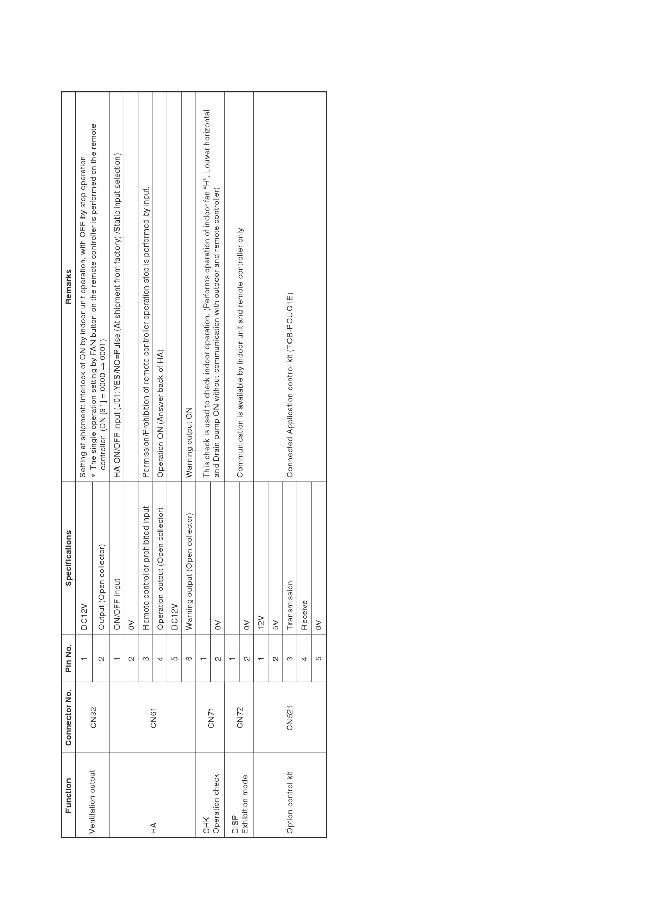
FILE NO. SVM-13050
Optional Connector Specifications of Indoor P.C. Board
- 38 -
FILE NO. SVM-13050
6. TROUBLESHOOTING
6-1. Summary of Troubleshooting
<Wired remote controller type>
1. Before troubleshooting
1)
Required tools/instruments
•
+ and - screwdrivers, spanners, radio cutting pliers, nippers, push pins for reset switch
• Tester, thermometer, pressure gauge, etc.
2)
Confirmation points before check
a) The following operations are normal.
1. Compressor does not operate.
• Is not 3-minutes delay (3 minutes after compressor OFF)?
• Is not the outdoor unit in standby status though the remote controller reached the setup
temperature?
• Does not timer operate during fan operation?
• Is not an overflow error detected on the indoor unit?
• Is not outside high-temperature operation controlled in heating operation?
2. Indoor fan does not rotate.
• Does not cool air discharge preventive control work in heating operation?
3. Outdoor fan does not rotate or air volume changes.
• Does not high-temperature release operation control work in heating operation?
• Does not outside low-temperature operation control work in cooling operation?
• Is not defrost operation performed?
4. ON/OFF operation cannot be performed from remote controller.
• Is not the control operation performed from outside/remote side?
• Is not automatic address being set up?
(When the power is turned on at the first time or when indoor unit address setting is changed, the
operation cannot be performed for maximum approx. 5 minutes after power-ON.)
• Is not being carried out a test run by operation of the outdoor controller?
b) Did you return the cabling to the initial positions?
c) Are connecting cables of indoor unit and remote controller correct?
2. Troubleshooting procedure
When a trouble occurred, check the parts along with the following procedure.
Trouble
→
Confirmation of check code display
→
Check defective position and parts.
NOTE :
For cause of a trouble, power conditions or malfunction/erroneous diagnosis of microcomputer due to outer
noise is considered except the items to be checked. If there is any noise source, change the cables of the
remote controller to shield cables.
- 39 -
FILE NO. SVM-13050
<Wireless remote controller type>
1. Before troubleshooting
1)
Required tools/instruments
•
+ and - screwdrivers, spanners, radio cutting pliers, nippers, etc.
• Tester, thermometer, pressure gauge, etc.
2)
Confirmation points before check
a) The following operations are normal.
1. Compressor does not operate.
• Is not 3-minutes delay (3 minutes after compressor OFF)?
• Is not the outdoor unit in standby status though the remote controller reached the setup
temperature?
• Does not timer operate during fan operation?
• Is not an overflow error detected on the indoor unit?
• Is not outside high-temperature operation controlled in heating operation?
2. Indoor fan does not rotate.
• Does not cool air discharge preventive control work in heating operation?
3)
Outdoor fan does not rotate or air volume changes.
• Does not high-temperature release operation control work in heating operation?
• Does not outside low-temperature operation control work in cooling operation?
• Is not defrost operation performed?
4)
ON/OFF operation cannot be performed from remote controller.
• Is not forced operation performed?
• Is not the control operation performed from outside/remote side?
• Is not automatic address being set up?
• Is not being carried out a test run by operation of the outdoor controller?
a) Did you return the cabling to the initial positions?
b) Are connecting cables between indoor unit and receiving unit correct?
2. Troubleshooting procedure
(When the power is turned on at the first time or when indoor unit address setting is changed, the operation
cannot be performed for maximum approx. 5 minutes after power-ON.)
When a trouble occurred, check the parts along with the following procedure.
Confirmation of the signal receiving unit
Check defective
Trouble
→
→
lamp display
position and parts.
1) Outline of judgment
The primary judgment to check where a trouble occurred in indoor unit or outdoor unit is performed with
the following method.
Method to judge the erroneous position by flashing indication on the display part of indoor unit
(sensors of the receiving unit)
The indoor unit monitors operating status of the air conditioner, and the blocked contents of
self-diagnosis are displayed restricted to the following cases if a protective circuit works.
- 40 -

FILE NO. SVM-13050
6-2. Troubleshooting
6-2-1. Outline of judgment
The primary judgment to check whether a trouble occurred in the indoor unit or outdoor unit is carried out with
the following method.
Method to judge the erroneous position by flashing indication on the display part of the indoor unit
(sensors of the receiving part)
The indoor unit monitors the operating status of the air conditioner, and the blocked contents of self-diagnosis
are displayed restricted to the following cases if a protective circuit works.
: Go off,
: Go on,
: Flash (0.5 sec.)
Lamp indication
Check code
Cause of trouble occurrence
Operation Timer
Ready
—
Power supply OFF or miswiring between receiving unit and indoor unit
No indication at all
E01
⎫
Receiving error
⎫
⎬
Receiving unit
⎪
Sending error
⎭
Miswiring or wire connection error
E02
⎬
between receiving unit and indoor unit
⎪
Communication stop
E03
⎭
Operation
Timer Ready
E08
Duplicated indoor unit No.
⎫
⎬
Setup error
E09
Duplicated master units of remote controller
⎭
Flash
E11
Communication error between Application control kit and indoor unit P.C. board
Wire connection error between indoor units, Indoor power OFF
E18
(Communication stop between indoor master and follower or between main
and sub indoor twin)
Operation
Timer Ready
Miswiring between indoor unit and outdoor unit or connection erorr
E04
(Communication stop between indoor and outdoor units)
Flash
Operation
Timer Ready
⎫
P10
Overflow was detected.
⎪
⎬
Protective device of indoor unit worked.
⎪
P12
Indoor DC fan error
Alternate flash
⎭
P03
Outdoor unit discharge temp. error
⎫
Protective device of
⎬
∗1
outdoor unit worked.
P04
Outdoor high pressure system error
⎭
P05
Negative phase detection error
⎫
⎪
P07
Heat sink overheat error
⎬
Outdoor unit error
⎪
Operation
Timer Ready
P15
Gas leak detection error
⎭
P19
4-way valve system error (Indoor or outdoor unit judged.)
Alternate flash
P20
Outdoor unit high pressure protection
P22
Outdoor unit: Outdoor unit error
⎫
⎪
Protective device of
P26
Outdoor unit: Inverter Idc operation
⎬
∗1
⎪
outdoor unit worked.
P29
Outdoor unit: Position detection error
⎭
Stopped because of error of other indoor unit in a group
P31
(Check codes of E03/L03/L07/L08)
∗1: These are representative examples and the check code differs according to the outdoor unit to be combined.
- 41 -

FILE NO. SVM-13050
Lamp indication
Check code
Cause of trouble occurrence
Operation Timer
Ready
F01
Heat exchanger sensor (TCJ) error
⎫
⎪
F02
Heat exchanger sensor (TC) error
⎬
Indoor unit sensor error
⎪
Alternate flash
F10
Heat exchanger sensor (TA) error
⎭
F04
Discharge temp. sensor (TD) error
⎫
⎪
⎪
F06
Temp. sensor (TE) error
⎪
⎪
Operation Timer
Ready
F07
Temp. sensor (TL) error
⎪
⎪
F08
Temp. sensor (TO) error
⎬
Sensor error of outdoor unit
∗1
⎪
Alternate flash
F12
Temp. sensor (TS) error
⎪
⎪
⎪
F13
Temp. sensor (TH) error
⎪
⎪
F15
Temp. Sensor miswiring (TE, TS)
⎭
Operation Timer
Ready
F29
Indoor EEPROM error
Simultaneous flash
Operation Timer
Ready
F31
Outdoor EEPROM error
Simultaneous flash
H01
Compressor break down
⎫
⎪
Operation Timer
Ready
H02
Compressor lock
⎪
⎬
Outdoor compressor system error
∗1
H03
Current detection circuit error
⎪
⎪
Flash
H04
Case thermostat worked.
⎭
H06
Outdoor unit low pressure system error
L03
Duplicated master indoor units
⎫
⎪
→ AUTO address
⎬
There is indoor unit of group connection
Operation Timer
Ready
L07
⎪
in individual indoor unit.
* If group construction and
⎭
address are not normal
L08
Unsetting of group address
when power supply turned on,
Simultaneous flash
automatically goes to address
setup mode.
Missed setting
L09
(Unset indoor capacity)
L10
Unset model type (Service board)
⎫
⎪
Operation Timer
Ready
L20
Duplicated indoor central addresses
⎪
⎪
L29
Outdoor unit and other error
⎬
Others
⎪
Simultaneous flash
L30
Outside interlock error
⎪
⎪
L31
Negative phase error
⎭
∗1: These are representative examples and the check code differs according to the outdoor unit to be combined.
- 42 -

FILE NO. SVM-13050
6-2-2. Others (Other than Check Code)
Lamp indication
Check code
Cause of trouble occurrence
Operation Timer
Ready
—
During test run
Simultaneous flash
Operation Timer
Ready
Disagreement of cool/heat
—
(Automatic cool/heat setting to automatic cool/heat prohibited model, or
setting of heating to cooling-only model)
Alternate flash
- 43 -

6-2-3. Check Code List (Indoor)
: Go on,
: Flash,
: Go off ALT (Alternate): Alternate flashing when there are two flashing LED SIM (Simultaneous): Simultaneous flashing when there are two flashing LED
(Indoor unit detected)
Check code indication
Lamp indication
Air conditioner operation
TCC-LINK central &
Block indication
Representative defective position
Explanation of error contents
Automatic
Operation
Wired remote controller
Operation Timer Ready
Flash
reset
continuation
Regular communication error between indoor and
No communication from remote controller and network adapter
E03
×
remote controller
(Also no communication from central control system)
E04
Indoor/Outdoor serial error
There is error on serial communication between indoor and outdoor units
×
E08
Duplicated indoor addresses
Same address as yours was detected.
×
E11
Communication error between Application control kit and indoor unit
Communication error between Application control kit and indoor unit P.C. board
×
Regular communication error between
Regular communication between indoor header and follower units is impossible,
E18
×
indoor master and follower units
Communication between twin header (main) and follower (sub) units is impossible.
F01
ALT
Indoor unit, Heat exchanger (TCJ) error
Open/short was detected on heat exchanger (TCJ).
×
F02
ALT
Indoor unit, Heat exchanger (TC) error
Open/short was detected on heat exchanger (TC).
×
F10
ALT
Indoor unit, Room temp. sensor (TA) error
Open/short was detected on room temp. sensor (TA).
×
F29
SIM
Indoor unit, other indoor P.C. board error
EEPROM error (Other error may be detected. If no error, automatic address is repeated.
×
×
L03
SIM
Duplicated setting of indoor group master unit
There are multiple master units in a group.
×
×
L07
SIM
There is group cable in individual indoor unit.
When even one group connection indoor unit exists in individual indoor unit.
×
×
L08
SIM
Unset indoor group address
Indoor group address is unset.
×
×
L09
SIM
Unset indoor capacity
Capacity of indoor unit is unset.
×
×
L20
SIM
Duplicated central control system address
Duplicated setting of central control system address
×
L30
SIM
Outside error input to indoor unit (Interlock)
Abnormal stop by outside error (CN80) input
×
×
P01
ALT
Indoor unit, AC fan error
An error of indoor AC fan was detected. (Fan motor thermal relay worked.)
×
×
P10
ALT
Indoor unit, overflow detection
Float switch worked.
×
×
P12
ALT
Indoor unit, DC fan error
Indoor DC fan error (Over-current/Lock, etc.) was detected.
×
×
P19
ALT
4-way valve system error
In heating operation, an error was detected by temp. down of indoor heat exchanger sensor.
×
P31
ALT
Other indoor unit error
Follower unit in group cannot operate by warning from [E03/L03/L07/L08] of header unit.
×
When this warning was detected before group construction/address check finish at power supply was turned on, the mode shifts automatically to AUTO address setup mode.
(Remote controller detected)
Check code indication
Lamp indication
Air conditioner operation
Block indication
Representative defective position
Explanation of error contents
Automatic
Operation
Wired remote controller
reset
continuation
Operation Timer Ready
Flash
No master remote controller, Remote controller
Signal cannot be received from indoor unit. Master remote controller was not set.
E01
—
—
communication (Receive) error
(including 2 remote controllers)
E02
Remote controller communication (Send) error
Signal cannot be sent to indoor unit.
—
—
In 2-remote controller control, both were set as master. (Indoor master unit stops warning
E09
Duplicated master remote controller
×
and follower unit continues operation.)
(Central control devices detected)
Check code indication
Lamp indication
Air conditioner operation
Block indication
Representative defective position
Explanation of error contents
Automatic
Operation
TCC-LINK central
Operation Timer Ready Flash
reset
continuation
Is not displayed.
Signal sending operation of central control system is impossible.
C05
Central control system communication (send) error
—
—
(Common use of wired
There are multiple same central devices. (AI-NET)
C06
remote controller, etc.)
Central control system communication (receive) error
Signal receiving operation of central control system is impossible.
—
—
An error on device connected to general-purpose device control interface of exclusive to
C12
—
General-purpose device control interface batched warning
—
—
TCC-LINK/AI-NET
P30
By warning unit
Group follower unit is defective.
Group follower unit is defective.
—
—
(Above-mentioned)
(For remote controller, above-mentioned [∗∗∗] details are displayed with unit No.
NOTE: Even for the same contents of error such as communication error, the display of check code may differ according to detection device.
When wired remote controller or central controller detects an error, it is not necessarily related to operation of the air conditioner. In this list, the check codes that outdoor unit detects are not described.

FILE NO. SVM-13050
Error mode detected by indoor unit
Operation of diagnostic function
Judgment and measures
Check
Status of
Cause of operation
Condition
code
air conditioner
1. Check cables of remote controller and communication adapters.
No communication from remote
Stop
Displayed when
E03
controller (including wireless) and
• Remote controller LCD display OFF (Disconnection)
(Automatic reset)
error is detected
communication adapter
• Central remote controller [97] check code
The serial signal is not output from
1. Outdoor unit does not completely operate.
outdoor unit to indoor unit.
• Inter-unit wire check, correction of miswiring
• Miswiring of inter-unit wire
Stop
Displayed when
• Check outdoor P.C. board. Correct wiring of P.C. board.
E04
• Defective serial sending circuit on
(Automatic reset)
error is detected
2. When outdoor unit normally operates
outdoor P.C. board
Check P.C. board (Indoor receiving / Outdoor sending).
• Defective serial receiving circuit on
indoor P.C. board
E08
Duplicated indoor unit address
1. Check whether remote controller connection (Group/Individual)
was changed or not after power supply turned on
L03
Duplicated indoor master unit
(Finish of group construction/Address check).
Displayed when
* If group construction and address are not normal when the
Stop
There is group wire in individual indoor
error is detected
power has been turned on, the mode automatically shifts to
L07
unit.
address setup mode. (Resetting of address)
L08
Unset indoor group address
Displayed when
1. Set indoor capacity (DN=11)
L09
Unset indoor capacity
Stop
error is detected
Displayed when
1. Check outside devices.
L30
Abnormal input of outside interlock
Stop
error is detected
2. Check indoor P.C. board.
1. Trouble of drain pump
Float switch operation
Displayed when
2. Clogging of drain pump
P10
Stop
• Float circuit, Disconnection,
error is detected
3. Check float switch.
Coming-off, Float switch contact error
4. Check Application control kit (TCB-PCUC1E)
1. Position detection error
Displayed when
2. Check fan motor (Protective circuit operation).
P12
Indoor DC fan error
Stop
error is detected
3. Indoor fan locked.
4. Check indoor P.C. board.
1. Check 4-way valve.
4-way valve system error
Stop
Displayed when
2. Check 2-way valve and check valve.
P19
• After heating operation has started,
(Automatic reset)
error is detected
indoor heat exchangers temp. is
3. Check indoor heat exchanger (TC/TCJ).
down.
4. Check indoor P.C. board.
Stop
1. Judge follower unit while master unit is [E03], [L03], [L07] or [L08].
Own unit stops while warning is output
Displayed when
P31
(Follower unit)
to other indoor units.
error is detected
2. Check indoor P.C. board.
(Automatic reset)
Coming-off, disconnection or short of
1. Check indoor heat exchanger temp. sensor (TCJ).
Stop
Displayed when
F01
indoor heat exchanger temp. sensor
(Automatic reset)
error is detected
2. Check indoor P.C. board.
(TCJ)
Coming-off, disconnection or short of
1. Check indoor heat exchanger temp. sensor (TC).
Stop
Displayed when
F02
indoor heat exchanger temp. sensor
(Automatic reset)
error is detected
2. Check indoor P.C. board.
(TC)
Coming-off, disconnection or short of
1. Check indoor heat exchanger temp. sensor (TA).
Stop
Displayed when
F10
indoor heat exchanger temp. sensor
(Automatic reset)
error is detected
2. Check indoor P.C. board.
(TA)
Indoor EEPROM error
Stop
Displayed when
1. Check indoor EEPROM. (including socket insertion)
F29
• EEPROM access error
(Automatic reset)
error is detected
2. Check indoor P.C. board.
Communication error between
Stop
Displayed when
1. Check power supply/communication harness.
Application control kit and indoor unit
(Automatic reset)
error is detected
2. Check indoor P.C. board.
E11
1. Check remote controller wiring.
Regular communication error between
Stop
Displayed when
E18
indoor aster and follower units and
2. Check indoor power supply wiring.
(Automatic reset)
error is detected
between main and sub units
3. Check indoor P.C. board.
- 45 -

FILE NO. SVM-13050
Error mode detected by remote controller or central controller (TCC-LINK)
Operation of diagnostic function
Judgment and measures
Status of
Check code
Cause of operation
Condition
air conditioner
Power supply error of remote controller, Indoor
EEPROM error
1. Check remote controller inter-unit wiring.
No communication with master indoor unit
2. Check remote controller.
Not displayed at all
(Operation on
• Remote controller wiring is not correct.
3. Check indoor power wiring.
Stop
—
remote controller
• Power of indoor unit is not turned on.
4. Check indoor P.C. board.
is impossible.)
• Automatic address cannot be completed.
5. Check indoor EEPROM.
(including socket insertion)
→ Automatic address repeating phenom-
enon generates.
Receiving error from remote controller
No communication with master indoor unit
Stop
1. Check remote controller inter-unit wiring.
E01
• Disconnection of inter-unit wire between
(Automatic reset)
Displayed when
2. Check remote controller.
∗2
remote controller and master indoor unit
∗ If center exists,
error is detected
(Detected by remote controller side)
operation continues.
3. Check indoor power wiring.
4. Check indoor P.C. board.
Stop
Sending error of remote controller
(Automatic reset)
Signal send error to indoor unit
Displayed when
1. Check sending circuit inside of remote
E02
(Detected by remote controller side)
∗ If center exists,
error is detected
controller.
operation continues.
→ Replace remote controller.
1. In 2-remote controllers (including wireless),
There are multiple main remote controllers.
Stop
Displayed when
there are multiple header units.
E09
(Follower unit
(Detected by remote controller side)
error is detected
Check that there are 1 main remote
continues operation.)
controller and other sub remote controllers.
L20
1. Check setting of central control system
Duplicated indoor central addresses on
Stop
Displayed when
network address. (Network adapter SW01)
communication of central control system
(Automatic reset)
error is detected
Central controller
2. Check network adapter P.C. board.
(Detected by indoor/central controller side)
L20
—
1. Check communication wire / miswiring
∗3
2. Check communication (U3, U4 terminals)
Communication circuit error of central
3. Check network adapter P.C. board.
Central controller
Continues
Displayed when
control system
(By remote controller)
4. Check central controller (such as central
(Send)
error is detected
(Detected by central controller side)
control remote controller, etc.)
C05
5. Check terminal resistance. (TCC-LINK)
(Receive)
C06
—
Continuation/Stop
Indoor Gr sub unit error
Displayed when
Check the check code of the corresponding
(According
Central controller
(Detected by central controller side)
error is detected
unit from remote controller.
to each case)
P30
∗2
The check code cannot be displayed by the wired remote controller.
(Usual operation of air conditioner becomes unavailable.)
For the wireless models, an error is notified with indication lamp.
∗3
This trouble is related to communication of remote controller (A, B), central system (TCC-LINK U3, U4), and
[E01], [E02], [E03], [E09] or [E18] is displayed or no check display on the wired remote controller according to
the contents.
- 46 -

FILE NO. SVM-13050
6-2-4. Diagnostic Procedure for Each Check Code (Indoor Unit)
Check code
[E01 error]
NO
Correct inter-unit cable
Is inter-unit cable of A and B normal?
of remote controller
YES
Is there no disconnection or
YES
Correct connection of connector.
contact error of connector on harness
Check circuit wiring.
from terminal block of indoor unit?
NO
NO
Is group control operation?
YES
NO
Check power connection of indoor unit.
Is power of all indoor units turned on?
(Turn on power again.)
YES
Is power supplied to remote controller?
NO
Check indoor P.C. board (MCC-1643).
AB terminal: Approx. DC18V
Defect → Replace
YES
Are 2 remote controllers set
YES
Correct a header unit/a follower unit.
without header unit?
(Remote controller address connector)
NO
Check remote controller P.C. board.
Defect → Replace
[E09 error]
YES
Are 2 master units set in
Correct as a header unit
2 remote controllers?
and a follower unit.
NO
Check remote controller P.C. board.
Defect → Replace
- 47 -

FILE NO. SVM-13050
[E04 error]
NO
NO
Is group address setup of
Does outdoor operate?
Check CODE No. [14].
remote controller correct?
YES
YES
NO
Are wiring in indoor unit and
Correct wiring and
1, 2, 3 inter-unit cables correct?
inter-unit cables.
YES
NO
Are wirings of terminal blocks
Correct wiring of connector
(1, 2, 3) wired to CN67 normal?
and terminal blocks.
YES
NO
Check indoor P.C. board.
Does the voltage between 2 and 3
(MCC-1643)
of terminal blocks (1, 2, 3) vary?
Defect → Replace
YES
Check indoor P.C. board.
Check outdoor P.C. board.
Defect → Replace
Defect → Replace
∗ As shown in the following figure,
carry out measurement within 20 seconds
after the power was turned on.
S5277G
Black
3
White
2
1
Terminal block
- 48 -

FILE NO. SVM-13050
[E11 error]
Is the
connection for the
UART communication
Yes
Repair of connector
connector (Internal board
connection.
CN521 red/Optional
board CN1 red)
normal?
No
Is connector
Yes
lead wire for the UART
Replacement of the
communication
connector’s lead wire.
cut?
No
Red LED (LD1)
Yes
Lead wire is cut or fault
of external output board
of input/output board.
not illuminated.
No
Red LED (LD1)
Yes
Fault with the external
light on the external input/
input/output board
output board flashes
ˠ Replace
on and off.
No
Red LED (LD1)
Yes
Fault with the internal
of external input/output
board (MCC-1643)
board blinks.
ˠ Replace
No
Check the operating status.
- 49 -

FILE NO. SVM-13050
[E18 error]
NO
Is inter-unit cable
Correct inter-unit cable
of A and B normal?
of remote controller.
YES
Is there no disconnection
YES
or contact error of connector
Correct connection of connector.
on harness from terminal block
Check circuit wiring.
of indoor unit?
NO
NO
Is group control operation?
YES
NO
Check power
Is power of all indoor units turned on?
connection status of indoor unit
(Connect again).
YES
NO
Is Twin or Triple control?
YES
Is there no contact error
YES
Correct indoor/outdoor inter-unit cable
of indoor/outdoor inter-unit cable
(Serial signal line).
(Signal line) of the main unit?
NO
Check indoor P.C. board
(MCC-1643).
Defect → Replace
[E08, L03, L07, L08 error]
E08: Duplicated indoor unit No.
L03: There are 2 or more master units in a group control.
L07: There is 1 or more group address [Individual] in a group control.
L08: The indoor group address is unset. (CODE No. 99)
If the above error is detected when power supply turned on, the mode enters automatically in the automatic
address set mode. (Check code is not output.)
However, if the above error is detected during the automatic address set mode, a check code may be
output.
[L09 error]
YES
Is not yet capacity setting
Set capacity data of indoor unit.
of indoor unit set up?
(Setup CODE No. (DN)=11)
NO
Check indoor P.C. board (MCC-1643).
Defect → Replace
- 50 -
FILE NO. SVM-13050
[L20 error]
Are wiring connections
NO
to communication lines
Correct wiring connection.
U3 and U4 normal?
YES
YES
Is not the multiple same central
Correct central control system address.
control system addresses connected?
NO
Check central controller
(including network adapter) and
indoor P.C. board (MCC-1643).
Defect → Replace
[L30 error]
Do outside devices normally work?
NO
Check outside devices.
(Outside devices connected with Application
Defect → Replace
control kit input terminal TB2 : IN1)
YES
Check cause of operation.
[P30 error] (Central controller)
NO
Is group operation carried out?
YES
Is there check code
NO
on follower unit in main
and sub remote controllers?
YES
Check corresponding
Check indoor P.C. board (MCC-1643).
indoor unit/outdoor unit.
Defect → Replace
- 51 -

FILE NO. SVM-13050
[P10 error]
Is connection of
NO
float switch connector
Correct connection
(Indoor control board CN34)
of connector.
normal?
YES
NO
YES
Check indoor P.C. board
Does float switch work?
Is circuit wiring normal?
(MCC-1643).
Defect → Replace
YES
NO
Check and correct wiring
and wire circuit.
NO
Does drain pump work?
YES
NO
Replace drain pump
Is power of
and indoor P.C. board
drain pump turned on? ∗
(MCC-1643).
YES
Check the drain pipe, etc.
Replace drain pump.
Check wiring.
∗ Check that voltage of 1-2 pin of CN504 on the indoor P.C. board is +12V. (1 pin is plus (+).)
[F10 error]
NO
Is connection of TA sensor connector
Correct connection of connector.
(CN104 on indoor P.C. board) correct?
YES
NO
Are characteristics of
Replace TA sensor.
TA sensor resistance value normal?
YES
∗ Refer to Characteristics-1.
Check indoor P.C. board (MCC-1643).
Defect → Replace
- 52 -

FILE NO. SVM-13050
[P12 error]
Power off.
Is not
connection error or
YES
Repair the connector
disconnection on the connector
connection.
CN210 of indoor unit
P.C. board?
NO
Disconnect the connector CN210 to
the indoor P.C. board
Does the
NO
Replace the indoor
fan turn smoothly when
fan motor.
turned by hand?
YES
Is each
resistance value
on the motor side of the
NO
Replace the indoor
fan motor connector CN210
fan motor.
of the indoor P.C.
Model name for the indoor fan motor.
board correct?
ICF-340WD94-1, CF-340WD94-2, ICF-340WD139-1
<Checking procedure>
YES
Measure the resistance of the following terminals with the tester.
Internal motor circuit is damaged if the measured value is out of
the range in below table.
Pin No.
7
6
5
4
3
2
1
Color
Blue
Yellow
White
Black
-
-
Red
˞ Measure by connecting the com side to 4 (Black) while measuring.
The measurement may vary.
Measurement place
Resistance value
a, b, c
I.
Between 4 (Black) - 1 (Red)
ʿ (MЊ)
II.
Between 4 (Black) - 5 (White)
35k - 65kЊ
III.
Between 4 (Black) - 6 (Yellow)
130k - 170kЊ
IV.
Between 4 (Black) - 7 (Blue)
ʿ (MЊ)
[Action if the measurement is out of the range]
If any measurement in the above table is between 0 to several
100 Ω, replace the indoor P.C. board together with the motor since
the indoor P.C. board is damaged.
Is F01 of the
YES
Replace the indoor P.C.
indoor P.C.
board (MCC-1643).
board open?
NO
Is R04 or R05
YES
Replace the indoor P.C.
of the indoor P.C.
board (MCC-1643).
board open?
NO
Check the indoor P.C.
board (MCC-1643).
If faulty Replace
– 53 -

FILE NO. SVM-13050
[P19 error]
Is operation of 4-way valve normal?
NO
NO
Are 1.3 to 1.6kΩ applied to
(Check the pipe temp., etc.
Replace 4-way valve coil.
resistance value of 4-way valve coil ?
during cooling/heating operation.
YES
YES
Defective
Check outdoor P.C. board operation.
Check outdoor P.C. board.
(See the following description.)
Defective → Replace
OK
Check outdoor temperature sensors.
TE sensor
TS sensor
Indoor TC sensor
Check 4-way valve.
Defective → Correct, replace
Defective → Replace
Operation check direction of the outdoor P.C. board (In case of self-preservation valve)
1) Set the Dip switch SW804 as same as the following table and push SW801 for approx. 1 second. It enables
you to check the exchange operation to cooling cycle or heating cycle.
• Only for approx. 10 seconds, the power is turned on.
• As the heat value of part (coil: resistance R700) is large, when checking the operation continuously, wait 1
minute or more until the next check. (There is no problem if a coil is not connected.)
2) After check, turn off all the Dip switches SW804.
Exchange to cooling cycle
Exchange to heating cycle
SW804
SW801
CN701
SW804
SW801
CN701
1
1
Push
Push
4
4
DC180V or more
DC180V or more
Check by tester
Analog tester: Good article if over DC180V
Digital tester: Although in some cases, the value varied and indicated. If the maximum value is DC180V or
more, it is good article.
- 54 -

FILE NO. SVM-13050
[F02 error]
NO
Is connection of TC sensor connector
Correct connection of connector.
(CN101 on Indoor P.C. board) correct?
YES
NO
Are characteristics of
Replace TC sensor.
TC sensor resistance value normal?
YES
∗ Refer to Characteristics-2.
Check indoor P.C. board (MCC-1643).
Defect → Replace
[F01 error]
NO
Is connection of TCJ sensor connector
Correct connection of connector.
(CN102 on Indoor P.C. board) correct?
YES
NO
Are characteristics of
Replace TCJ sensor.
TCJ sensor resistance value normal?
YES
∗ Refer to TCJ sensor
(Temperature-Resistance value characteristic table)
Check indoor main P.C. board (MCC-1643).
Defect → Replace
- 55 -

FILE NO. SVM-13050
[C06 error] (“1:1 model” connection interface)
NO
Are U3 and U4 communication lines normal?
Correct communication line.
YES
NO
∗1
Correct connection of connector.
Is connection of connector normal?
YES
∗1
TCC-LINK central:
CN51 of “1:1 model” connection interface (TCC-LINK adapter) P.C. board (MCC-1440) and
CN050 of indoor P.C. board
NO
Check connection of A and B terminal blocks.
Are A and B communication lines normal?
Correct communication line of remote controller.
YES
YES
Is there no connection error of power supply cable?
Correct power wiring.
NO
NO
Is not the source power supply turned on?
Turn on the source power supply.
YES
YES
Did a power failure occur?
NO
YES
Is the network address changed
Clear the check code.
from the wired remote controller?
NO
YES
Is there no noise source?
Eliminate noise, etc.
NO
Uncontrolled
Can the other indoor units
(Same to others)
Check central controller.
be normally controlled from the central controller?
Defect → Replace
Or is the operation status of indoor unit reflected?
YES
Uncontrolled
Can the indoor unit be normally controlled
Check indoor P.C. board (MCC-1643).
from the remote controller?
Defect → Replace
YES
Check power supply transformer on
“1:1 model” connection interface (MCC-1440).
Defect → Replace
- 56 -
FILE NO. SVM-13050
[E03 error] (Header indoor unit)
[E03 error] is detected when the indoor unit cannot receive a signal from the remote controller
(also central controller).
Check A and B remote controllers and communication lines of the central control system U3 and U4.
As communication is impossible, this check code [E03] is not displayed on the remote controller and the central
controller. [E01] is displayed on the remote controller and [C06 error] is displayed on the central controller.
If these check codes generate during operation, the air conditioner stops.
[F29 error]
This check code indicates a detection error of IC503 non-volatile memory (EEPROM) on the indoor unit P.C.
board, which generated during operation of the air conditioner. Replace the service P.C. board.
∗ When EEPROM was not inserted when power supply turned on or when the EEPROM data read/write
operation is impossible at all, the automatic address mode is repeated. In this time, [C06 error] is displayed
on the central controller.
(Approx.
(Approx.
3 minutes)
1 minute)
LED (D501) on indoor unit
[SET] is displayed
[SET]
Reboot
(Power ON)
P.C. board flashes with
on remote controller.
goes off.
(Reset)
1Hz for approx. 10 seconds.
(Repetition)
[P31 error] (Follower indoor unit)
When the header unit of a group operation detected [E03], [L03], [L07] or [L08] error, the follower unit of the
group operation detects [P31 error] and then the unit stops.
There is no display of the check code or alarm history of the wired remote controller. (In this model, the mode
enters in automatic address set mode when the header unit detected [L03], [L07] or [L08] error.)
- 57 -

FILE NO. SVM-13050
Temperature sensor
Temperature - Resistance value characteristic table
TA, TC, TCJ, TE, TS, TO sensors
TD, TL sensors
Representative value
Representative value
Temperature
Resistance value (kΩ)
Temperature
Resistance value (kΩ)
(°C)
(Minimum value)
(Standard value)
(Maximum value)
(°C)
(Minimum value)
(Standard value)
(Maximum value)
0
32.33
33.80
35.30
0
150.5
161.3
172.7
10
19.63
20.35
21.09
10
92.76
99.05
105.6
20
12.23
12.59
12.95
20
58.61
62.36
66.26
25
9.75
10.00
10.25
25
47.01
49.93
52.97
30
7.764
7.990
8.218
30
37.93
40.22
42.59
40
5.013
5.192
5.375
40
25.12
26.55
28.03
50
3.312
3.451
3.594
50
17.00
17.92
18.86
60
2.236
2.343
2.454
60
11.74
12.34
12.95
70
1.540
1.623
1.709
70
8.269
8.668
9.074
80
1.082
1.146
1.213
80
5.925
6.195
6.470
90
0.7740
0.8237
0.8761
90
4.321
4.507
4.696
100
0.5634
0.6023
0.6434
100
3.205
3.336
3.468
TA, TC, TCJ, TE, TS, TO sensors
40
30
20
10
0
0
10
20
30
40
50
60
70
80
90
100
Temperature (˚C)
TD, TL sensors
200
20
150
15
100
10
50
5
0
0
0
10
20
30
40
50
60
70
80
90
100
Temperature (˚C)
∗ As TH sensor (Outdoor unit heat sink temp. sensor) is incorporated in the outdoor control P.C. board, the resistance
value cannot be measured.
- 58 -

FILE NO. SVM-13050
7. REPLACEMENT OF SERVICE P.C. BOARD
7-1. Indoort Unit
CAUTION
<Model name: RAV-SM∗∗∗CTP∗>
For the above models, set the CODE No. “
” and the setting data “0000” (initial) to “0001”.
<Note: when replacing the P.C. board for indoor unit servicing>
The nonvolatile memory (hereafter called EEPROM, IC503) on the indoor unit P.C. board before replacement
includes the model specific type information and capacity codes as the factory-set value and the important
setting data which have been automatically or manually set when the indoor unit is installed, such as system/
indoor/group addresses, high ceiling select setting, etc.
When replacing the P.C. board for indoor unit servicing, follow the procedures below.
After replacement completes, confirm whether the settings are correct by checking the indoor unit No., Group
header unit/follower unit settings and perform the cooling cycle confirmation through the trial operation.
<Replacement procedures>
CASE 1
Before replacement, the indoor unit can be turned on and the setting data can be read out by
wired remote control operation.
EEPROM data read out [1]
Replacement of P.C. board for Indoor unit servicing and power on [2]
Writing the read out EEPROM data [3]
Power reset
(for all indoor units connected to the remote control when the group operation control is performed.)
CASE 2
The EEPROM before replacement is defective and the setting data cannot be read out.
EEPROM data read out [2]
Writing the setting data to EEPROM, such as high ceiling installation setting and
optional connection setting, etc., based on the customer information. [3]
Power reset
(for all indoor units connected to the remote control when the group operation control is performed.)
- 59 -
///////////////////////////////////////