Carrier 30AWH004HB / 30AWH006HB / 30AWH008HB / 30AWH012HB. Service Manual - page 2


  Главная      Manuals     Carrier 30AWH004HB / 30AWH006HB / 30AWH008HB / 30AWH012HB. Service Manual (2010)


Search            copyright infringement  


Content      ..      1      2      3      ..


Carrier 30AWH004HB / 30AWH006HB / 30AWH008HB / 30AWH012HB. Service Manual - page 2


17

30AW

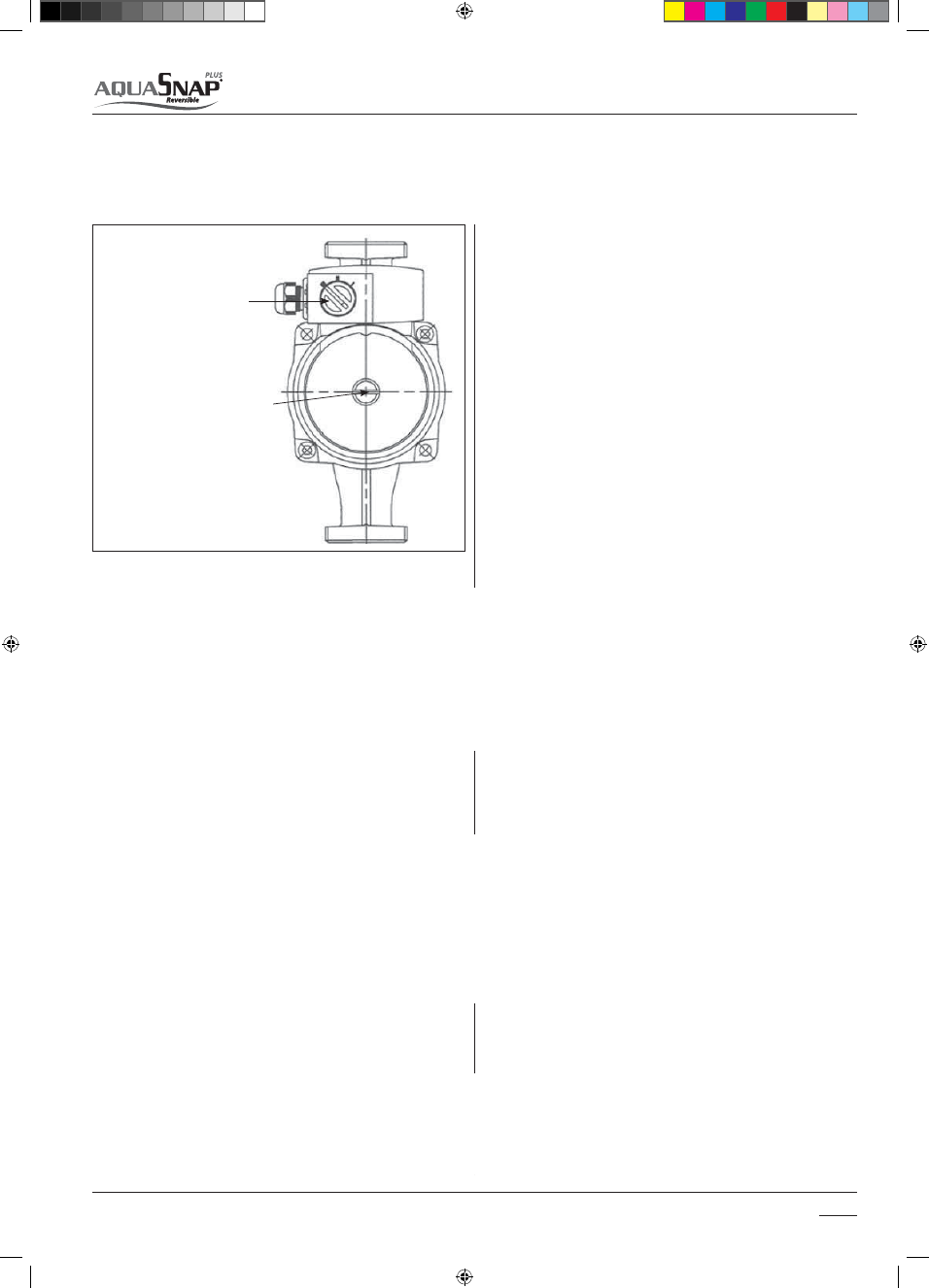
3.3.6 Circulating water Pump (only H version)

Water flow setting

Anti-seizing pump

Speed selector

Shaft protection plug

Pumps have a manual speed selector (3 speed settings) which allow for 
adjustment of speed to match the requirements of the system.

The 30AWH__H units are equipped with protection against the seizing 
of the pump motor shaft. To allow this function, do not empty the 
system or disconnect the power during long periods of inactivity.
In any case, if the pump rotor shaft seizes after a long period of 
inactivity, the user must do the following to unblock it:

Pump has to be selected in order to provide nominal water flow at 
expected water loop pressure loss.
Centrifugal Pump Curves.
Water loop pressure loss estimation at nominal water flow is needed to 
define water pump size.

Pump Speed Setting procedure:
The best speed setting will provide adequate circulation and provide 

UIFDPSSFDUøPXBOESFUVSOUFNQFSBUVSFEJòFSFOUJBMT5IJTXJMMBDIJFWF
NBYJNVNFDPOPNZBOEFóDJFODZ

Set the speed selector to minimum (one) 

1. 

Open all thermostatic or manual radiator valves to maximum 

2. 

Set any room thermostatic controls to maximum 

3. 

Start up system and pump should start 

4. 

8BJU_NJOTBOENFBTVSFXBUFSUFNQFSBUVSFEJòFSFOUJBM

5. 

(leaving water temperature-entering water temperature) 

8BUFS5FNQFSBUVSF%JòFSFOUJBMTIPVMECF¡$JG8BUFSEFMUB

6. 

temperature is more than 6°C select a higher pump speed An 

BMUFSOBUJWFTPMVUJPOJTNFBTVSFXBUFSQSFTTVSFEJòFSFOUJBMCFUXFFO

unit water IN-OUT pipes and select pump speed to match the unit 
nominal water flow (see unit available static pressure curves).

- Disconnect the power
- Remove the front panel
- Unscrew the shaft-protection plug on the back of the pump
- Insert a screwdriver in the slot and turn the rotor shaft
- Remount the protection plug
- Reconnect the power 

3.3.7 External water pump selection (X and NX version)

Pump Speed Setting procedure is the same used for 30AWH---H version.

"OBMUFSOBUJWFTPMVUJPOJTNFBTVSFXBUFSQSFTTVSFEJòFSFOUJBMCFGPSFBOE

after external water pump and select pump speed to match the unit 
nominal water flow (see water pump curves)


    Installation

3

14-03-2011   14:41:26

18

30AW


    Installation

3

Charge the water loop, with water, until the pressure on the hydro unit 
reads 0.15MPa (1.5bar ) 
Setting NUI Code104 (installation mode) = 1 water pump is forced on. 
Loosen the cap of the air purge valve located on the top of back up 
heater to purge air from the water circuit. If air remains in the system the 
system will not operate correctly. 

An expansion vessel has to be added in the water loop with 30AWH___X 
and 30AWH___NX.
The capacity of the internal expansion vessel fitted in 30AWH__H :

t MJUFSTGPSTJ[FTBOE
t MJUFSTGPSTJ[FBOE 'PSUIJTNPEFMUIFFYQBOTJPOWFTTFM

has been dimensioned for a typical terminal fan coil water loop)

If water loop content is higher than specified in the installation manual, 
an additional expansion vessel has to be added.
The expansion volume can be calculated using the following formula. 

 Looking for Code 111 (water flow switch status) the installer can verify if 
the water fill operating is completed (when water is flowing, parameter 
111 = 1)
When completing the Test Run, during the commissioning of the 
system, the water pressure  in the system may drop below 1,5 bar. In this 
event please add more water to the system. 
In the case of a new installation, or cleaning the circuit, it is necessary to 
perform a preventive cleaning of the system.
In order to guarantee the good operation of the product, each time you 
clean the system, replace the water or add glycol, check that the liquid 
appears clear, without visible impurities and that the hardness is less 
than 20 °f.

3.3.8 Water loop charging, system cleaning and Water Characteristics 

3.3.9 Expansion vessel (Volume calculation)

Where:
V:  Necessary total vessel capacity (L)

Ⱦ 8BUFSFYQBOTJPODPFóDJFOUBUBWFSBHFIPUXBUFSUFNQFSBUVSF

Vs: Total water volume in the closed system (Do not include Hot Water 

Cylinder)

P1: System pressure at tank setting position (Mpa_abs*). (Pipe inner 

pressure during pump operation before heating device operates = 
water supply pressure)

P2: Maximum pressure used during operation at tank setting position 

(Mpa_abs*=safety valve setting pressure)

* The absolute pressure valve (abs.) is obtained by adding the atmos-

pheric pressure (0,1 MPa (1 bar)) to the gauge pressure.

The initial pressure of this expansion Vessel is 0.1Mpa (1 bar).
The release pressure of the safety valve is 0.3Mpa (3 bar).

2

1

1

P

P

Vs

V

s

E

Water temperature and expansion coefficient (ε)

Water temperature and expansion coefficient (ε)

Hot water temperature (°C)

Expansion rate  (ε)

Hot water temperature (°C)

Expansion rate  (ε)

0

0.0002

50

0.0121

4

0.0000

55

0.0145

5

0.0000

60

0.0171

10

0.0003

65

0.0198

15

0.0008

70

0.0229

20

0.0017

75

0.0258

25

0.0029

80

0.0292

30

0.0043

85

0.0324

35

0.0050

90

0.0961

40

0.0078

95

0.0967

45

0.0100

-

-

Example:

 Maximum hot water temperature 55°C, initial water charge 0.2MPa and system volume 200 litres. The calculated Vessel capacity is:

)

1

.

0

3

.

0

(

)

1

.

0

2

.

0

(

1

200

0145

.

0

6

.

11

s

14-03-2011   14:41:27

19

30AW


    Installation

3

% Inhibited

Ethylene

Glycol

10%

20%

30%

40%

Freezing temperature (*) 

-4 °C

-9 °C

-15 °C

-23 °C

Correction

Factors

Capacity

0,996

0,991

0,983

0,974

Absorbed power 

0,990

0,978

0,964

1,008

Loss of head 

1,003

1,010

1,020

1,033

(*) Note: Temperature values are indicative.

Always refer to the temperatures indicated for the specific product used

Pipe water content

Internal Diameter

Outer diameter

Liters / meter

copper

12 mm

14 mm

0,11 l/m

14 mm

16 mm

0,15 l/m

16 mm

18 mm

0,20 l/m

20 mm

22 mm

0,31 l/m

25 mm

28 mm

0,49 l/m

32 mm

35 mm

0,80 l/m

steel

"12.7 mm (1/2'')"

3/8'' Gas

0,13 l/m

"16.3 mm (5/8'')"

1/2'' Gas

0,21 l/m

"21.7 mm (7/8'')"

3/4'' Gas

0,37 l/m

"27.4 mm (11/16'')"

1' Gas

0,59 l/m

Unit

30 AWH

004

006

008

012

015

Nominal water flow

Std

l/s

0,20

0,28

0,33

0,58

0,69

Water loop content for

30AWH___H units

Min

l

14

21

28

42

49

Max

l

65

65

65

95

95

Max water loop pressure

Max

kPa

300

300

300

300

300

Filling water pressure

Min

kPa

120

120

120

120

120

Max elevation 30AW upper

Max

m

20

20

20

20

20

TABLE TO USE FOR CALCULATING THE WATER CONTENT IN THE SYSTEM

Installed Unit 

.............

Unit content (*) 

l

.............

Pipe content (**) 

l

.............

Uses (fan-coil, panels, radiators, etc.) (***) 

l

.............

Total content (****) 

l

.............

(*) Consult the technical data table
(**) Consult the pipe water content table
(***) Consult the manual for the installed uses
(****) The water content of the system must be between the minimum and maximum values for the units with hydronic kit and greater than the minimum 
value for units without hydronic kit. The minimum value is necessary to provide optimal comfort. 
For units without hydronic kit, add a suitable expansion vessel to the water content of the system.

14-03-2011   14:41:27

20

30AW


    Installation

3

3.4 Refrigerant schematics

Refrigerant Circuit

Component

Component

0

4-way valve

9

TR sensor

1

TS sensor

10

Liquid tank

2

Check joint

11

Pulse Motor Valve

3

Accumulator

12

Distributor

4

Muffler

13

TE sensor

5

TD sensor

13*

TL sensor (only 015)

6

DC twin rotary compressor

14

Propellor fan

7

BPHE

15

TO sensor

8

Muffler

16

Heat exchanger

14-03-2011   14:41:28

21

30AW

The unit can be controlled and set via:

t6TFS$PNGPSU*OUFSGBDFXJSFDPOUSPM"8$4 0QUJPOBM
t8JSFSFNPUFDPOUSPM"83$ 0QUJPOBM
t4XJUDIFT OPUTVQQMJFE

                               Electrical connections

4

     WARNING 

Make water connections before electrical connections.
Make ground connection prior to any other electrical connections


All field electrical connections are the responsibility of the installer. 

Unit

30AWH

004_

006_

008_

012_

015_

Power supply

V- ph - Hz

230 - 1 -50

Allowable Voltage Range

V

207 ÷ 253

Maximum power drawn

kW

2

2.3

2,7

5.1

5.1

Maximum current drawn

A

7,2

11

14

 23 

20

Power Fuses

Type

gL type

Current

A

10 - B type

15 - B type

15 - B type

25 - D type

25 - D type

Power supply cables

mm2

H07RN-F 3 x 2.5mm2

Maximum Pump Current

External circulation 

A

2

Use cables H03VV-F 4x0.75 mm2 to connect the control to wire NUI

and H03VV-F 6x0.75 mm2 to connect the control to wire SUI

Check the supply voltage and frequency of the unit.
Remove the front panel, the electric parts appear at the front side.
The power supply cables can be inserted into the pipe holes. Be sure 
to fix the power cable with bundling band to avoid contact with the 
compressor and the hot pipes.
To ensure good tensile strength, the electric cables must be fastened 
using the cable-holder on the plate (Only for size 015 use the strain relif 
supplied with the unit).

WARNING:

t8SPOHXJSJOHNBZDBVTFBCVSOPVUUPTPNFFMFDUSJDBMQBSUT
t#FTVSFUPVTFUIFDPSEDMBNQTBUUBDIFEUPUIFQSPEVDU
t%POPUEBNBHFPSTDSBUDIUIFDPOEVDUJWFDPSFBOEJOOFSJOTVMBUPSPG

power and inter-connecting cables when peeling them.

t6TFUIFQPXFSBOE*OUFSDPOOFDUJOHDBCMFTXJUITQFDJöFEUIJDLOFTT

specified type and protective devices required.

t$POOFDUUIFDPOOFDUJOHDBCMFUPUIFUFSNJOBMBTJEFOUJöFEXJUIUIFJS

respective numbers on the terminal block of the unit.

t5IFNBJOTTVQQMZDPOOFDUJOHDBCMFNVTUCF)3/'UZQF *&$

57) or higher, with synthetic rubber insulation with Neoprene coating, 
according to EN 60335-2-40 codes.

t5IFJOTUBMMBUJPOGVTF #UZQF#UZQFPS%UZQFJOBDDPSEJOH

with the version) must be used for the power supply line of this heat 
pump.

t*ODPSSFDUJODPNQMFUFXJSJOHNJHIUDBVTFBOFMFDUSJDBMöSFPSTNPLF
t1SFQBSFUIFFYDMVTJWFQPXFSTVQQMZGPSUIFIFBUQVNQ
t&OTVSFUIBUNBJOTTVQQMZDPOOFDUJPOJTNBEFUISPVHIBTXJUDIUIBU

disconnects all poles, with contact gap of a least 3 mm.

/

  Power supply terminal block

0

 Power cable

1

Ground connector

Terminal block

/

 Earth line

0

 Power cable

10

10

L N

30

40

/

/

1

0

0

0

1

/

14-03-2011   14:41:29

22

30AW

Terminal Block X Version

                               Electrical connections

4

4.1 Auxiliary electrical connections


N N L

4 19 9

C W G Y

2 3 6 7

N N L

4 19 9

C W G Y

2 3 6 7

N    N     18


10    11


12 

4      5     16


13   14


15 


C W G  Y


23 24  1


 2   3   6  7


8   21  22 


Alarm / 

Ambient 
temperature 
reached 

External 
temperature


probe 


Alarm Input 

  3  Ways


valve 

   Alarm + defrost /


Dehumidifier

    Electric heater /


Additional Water


pump 

    External
heat source
/ defrost


33AW-RC1 

Remote control 

33AW-CS1 

Remote control 

    Limitation 
frequency

    Sanitary Input 


SUI ALARM 

+ 12 V 

ECO 
HTG/CLG 
ON/OFF 


N    N     18


10    11


12 

4      5     16


13   14


15


C W G  Y


23 24  1


 2   3   6   7


8   21  22


Alarm / 

Ambient 
temperature 
reached 

External 
temperature


probe 


Alarm Input 

  3  Ways


valve 

   Alarm + defrost /


Dehumidifier  

    Electric heater /


Additional Water


pump 

    External
heat source
/ defrost


33AW-CS1 

Remote control 

    Limitation 
frequency

    Sanitary Input 

   External Water 

pump 


33AW-RC1 

Remote control 

SUI ALARM 

+ 12 V 

ON/OFF 

HTG/CLG 

ECO 

Terminal Block H Version

   Output Dry-contact, High voltage

Input Dry-contact, Low voltage

14-03-2011   14:41:50

23

30AW

                               Electrical connections

4


N   N   L   10  20  12 

 4  19   9  13  14  15 

  C W G Y     23 24 1


 2  3  6  7      8  21 22 

N   N   L   10  20  12 

 4  19   9  13  14  15 

  C W G Y     23 24 1


 2  3  6  7      8  21 22 

1    2    3   4    5    6 

 7   8    9  10  11  12 


C W G Y     

13 14 15


    3 Ways 
valve 


External Pump 

     Alarm and 
defrost status


    Sanitary 
Input 

33AW-RC1 

Remote control 

33AW-CS1 

Remote control 

    Bus  
RS 485 

    Defrost signal or air 
temperature reached signal 

ON/OFF 

HTG/CLG 

Terminal Block NX Version

4.1.1 Sanitary hot water

The 30AWH units drive a 3-way valve (7) to manage a sanitary water 
accumulation tank. The operating logic provides that, in the case of 
a request for sanitary water by an accumulation tank (8), the system 
controls a 3-way valve to direct the hot water only to the tank and to 
operate at the maximum capacity to provide water at 60 °C (compatible 
with the operating envelope).
Procedure to install a three way valve:

1. Install three way valve on water piping closer as possible to 

AQUASNAP

2. Connect electrically three way valve to N, 18, 10 terminals (1,2 and 

QJOTJO/9WFSTJPOJODBTFPGUISFFXBZWBMWFXJUITQSJOHSFUVSO

only connect N and 10 terminals 

8

9

7

3. Connect Sanitary Hot Water dry contact thermostat/request (eg. 

45°C ON, 55°C OFF) to 13 and 15 terminals (7 and 8 in NX version) 

Closing that contact, GMC drives three way valve and AQUASNAP runs 

BU¡$JOIFBUJOHNPEFUPPCUBJOIPUXBUFS QSJPSJUZ4)8XIFO

contact opens, GMC drives back the system in the previous mode 

 DPPMJOHIFBUJOHPSPò 

Attention:

1) The sanitary water request has higher priority than the 

programmed operating mode in both heating and cooling mode.

2) NUI code 146 configure SHW logic when Aquasnap unit is in OFF 

mode.

14-03-2011   14:42:06

24

30AW

                               Electrical connections

4

Load 

TFC, floor or 

radiators 

Water collector 

Check valve 

Example

s

 of water circuitation: 

4.1.2 External heat source

4.1.3 Dehumidifier or a Humidifier

An External Heat Source can be driven by Aquasnap Plus.
For this feature is necessary install 33AW-CS1 interface
Procedure to install an External Heat Source 

Connect electrically EHS to N and 4 terminals to a relay that drives 

1. 

EHS
Configure parameter 106 through 33AW-CS1 interface (1 for EHS)

2. 

Configure outdoor temperature limits (parameter 148 and 150). 

3. 

A Dehumidifier or a Humidifier can be driven by Aquasnap 
Plus using humidity sensor into 33AW-CS1 interface.
For this feature is necessary install 33AW-CS1 interface

Connect electrically a Dehumidifier or a Humidifier to 

1. 

N, 11 terminals to a relay that drives Dehumidifier (NO 
contact) or a Humidifier (NC contact) 
Configure parameter 108 through 33AW-CS1. (2 for 

2. 

dehumidifier /Humid.)
Configure ambient humidity limit (parameter 107) 

3. 

where Dehumidifier or a Humidifier is activated (eg. 
with par.107 =  65, Dehumidifier is activated with 

BNCJFOUIVNJEJUZ63

When the OAT is less than second parameter both the HP and the 
EHS will be operative as per algorithm. 

8IFOUIF0"5JTMFTTUIBOöSTUQBSBNFUFS"RVBTOBQJTTXJUDIFEJOPò

mode and EHS is activated (eg.with par.148 = -2 EHS is activated with 
OAT < -2°C + hysteresis)
To change the delta T needed to activate the EHS change the 

4. 

parameter 152. (Factory default 5 °C).


14-03-2011   14:42:08

25

30AW

                               Electrical connections

4

4.1.4 Silent/night mode

4.1.5 Stop Unit or Defrosting signals

4.1.6 External temperature probe

Silent/night mode is a system setting to limit maximum AQUASNAP 
noise level.
Noise level is reduced limiting maximum compressor frequency.

&HSFEVDJOHBUNBYDPNQSFTTPSGSFRVFODZNBYJNVNOPJTFMFWFMJT

reduced of 3dBA

1. Configure code 5 through 33AW-CS1 interface or through DST (2 for 

Silent/night mode active).

$POöHVSFDPNQSFTTPSGSFRVFODZSFEVDUJPO /VJDPEFNBYJNVN

DPNQSFTTPSGSFRVFODZQBSBNFUFSSBOHFJTGSPNUP

3. Select Silent/night mode on scheduling  

This feature is available using 33AW-CS1 interface dry contact to 
frequency reduction mode (PINS 13-14).

There are several signals available on the terminal strip to indicate 
particular conditions or the stop of the external unit.
The available signals are: 

-  Defrosting: When operating in Heating mode, depending on the 

external environmental conditions, the unit could perform 

  defrosting  cycles to clean the external battery of any ice formations. 

Under these conditions, it is not possible to guarantee the reque-
sted temperature output water temperature, which could reduce 
general comfort. (PINS: 4-N or 11-N, NUI CODE: 106 or 108)

-  Alarm: Indicates an alarm condition that stops the compressor. 

(PINS: 5-N or 11-N, NUI CODE: 147 or108)

If the positioning of the external unit could induce a non-representative 
reading of the external temperature by the probe positioned on the 
machine, an additional temperature probe can be provided (NTC 2 wire, 

Units without an integrated pump allow driving an external one.

With the contact closed, the unit will operate with a maximum 
frequency lower than the standard one, otherwise it will operate in 
standard mode.

Short-Cut to Frequency reduction Mode

Press the active key among Hold (

) key for 10 seconds to make Night 

mode active and can de-activate the Night mode by pressing the Hold 
(

) key again for 10 seconds. When Frequency reduction / Night / 

Silence mode is active, NUI will display the (

) Icon. If FR mode is active, 

this will always override the selection done in program schedule.

-  Ambient Temperature Reached: If suitably programmed using the 

User Comfort Interface, and operating with this interface, a signal 
is provided that indicates that the ambient temperature has been 

SFBDIFE5IJTTJHOBMDBOCFVTFEUPUVSOPòGBODPJMT 1*/4//6*

CODE: 147)

Several outputs are used for more than one condition. It is possible to 
configure these outputs through the User Comfort Interface installation 
menu (refer to the 33AW-CS1 manual).
Refer to the tables of next page and figures on paragraph 4.1 for the 
correct pin-outs and use of the signals.

3kΩ @ 25°C, Carrier code: 33AW-RAS01) remote. Connect the terminals 
of the probe between PINS 23 and 24 of the terminal strip.

4.1.7 External water circulator for 30AWH__X and 30AWH__NX units

4.1.8 Additional Water pump (PINS 12-N)

The signal is supplied between PINS 16 and N of the terminal strip (PINS 
1 and 4 for the NX version).

It is managed in the following way:
If OAT > temperature set in nui code 148
The additional water pump activation depending by the nui code 156

1. ON/ OFF depending on the outdoor unit water pump logic, in case 

PG4)8BDUJWBUJPO"%%81JT0/

2. ON/ OFF depending on the outdoor unit water pump logic, in case 

PG4)8BDUJWBUJPO"%%81JT0''

If OAT < temperature set in nui code 148
The additional water pump activation depending by the nui code 157 
(0. always ON, 1. always OFF or 2. ON/OFF depending by EHS).

14-03-2011   14:42:09

26

30AW

30AWH__H

Description

PIN

Signal

Limits

33AW-CSI

Installation
Menu Code

Additional external temperature probe

23 - 24

Input (NTC 3kΩ @25°C)

N.A.

126

Sanitary Water Request

13 - 15

Input (contact switch quality

>25mA@12V)

N.A.

153

Maximum Frequency Reduction Compressor

13 - 14

Input (contact switch quality

>25mA@12V)

N.A.

5-6.

3-way valve

10 - 18 - N

Output 230Vac (18-N: Power

Suply, 10:Signal)

1 ph ~ 230V, 2A

N.A.

1- External Heat Source Request

2- Defrost

4 - N

Relay Output Contact

1 ph ~ 230V, 2A

106 - 148 -150 -151 - 

152 -154 -155

1- Alarm 

2- Ambient temperature reached

5 - N

Relay Output Contact

1 ph ~ 230V, 2A

147

1- Alarm + defrost

2- Humidifier

11 - N

Relay Output Contact

1 ph ~ 230V, 2A

107 - 108

1- Trace heater

2- Additional WP

12 - N

Relay Output Contact

1 ph ~ 230V, 2A

156 - 157

Alarm input

21

Input (contact switch quality

>25mA@12V)

N.A.

N.A.

ON / OFF

6 - 3

Dry contact

N.A.

N.A.

NORMAL / ECO Mode

8 - 3

Dry contact

N.A.

N.A.

Heating / Cooling Mode

7 - 3

Dry contact

N.A.

N.A.

30AWH__X

Description

PIN

Signal

Limits

33AW-CSI

Installation
Menu Code

Additional external temperature probe

23 - 24

Input (NTC 3kΩ @25°C)

N.A.

126

Sanitary Water Request

13 - 15

Input (contact switch quality

>25mA@12V)

N.A.

153

Maximum Frequency Reduction Compressor

13 - 14

Input (contact switch quality

>25mA@12V)

N.A.

5-6

3-way valve

10 - 18 - N

Output 230Vac (18-N: Power

Suply, 10:Signal)

1 ph ~ 230V, 2A

N.A.

1- External Heat Source Request

2- Defrost

4 - N

Relay Output Contact

1 ph ~ 230V, 2A

106 - 148 -150 -151 - 

152 -154 -155

1- Alarm 

2- Ambient temperature reached

5 - N

Relay Output Contact

1 ph ~ 230V, 2A

147

1- Alarm + defrost

2- Humidifier

11 - N

Relay Output Contact

1 ph ~ 230V, 2A

107 - 108

1- Trace heater

2- Additional WP

12 - N

Relay Output Contact

1 ph ~ 230V, 2A

156 - 157

Alarm input

21

Input (contact switch quality

>25mA@12V)

N.A.

N.A.

External water pump

16 - N

Relay Output Contact

1 ph ~ 230V, 2A

N.A.

ON / OFF

6 - 3

Dry contact

N.A.

N.A.

NORMAL / ECO Mode

8 – 3

Dry contact

N.A.

N.A.

Heating / Cooling Mode

7 – 3

Dry contact

N.A.

N.A.

30AWH__NX

Description

PIN

Signal

Limits

33AW-CSI

Installation
Menu Code

Sanitary Water Request

7 - 8

Input (contact switch quality

>25mA@12V)

N.A.

N.A.

3-way valve

1 - 2 - 3

Output 230Vac

1 ph ~ 230V, 2A

N.A.

Water Circulator

1 - 4

Output 230Vac

1 ph ~ 230V, 2A

N.A.

Alarm 

5 - 6

Input (contact switch quality

>25mA@12V)

N.A.

147

Defrost

9 - 10

Input (contact switch quality

>25mA@12V)

N.A.

106

BUS RS485

11 - 12

14-03-2011   14:42:10

27

30AW


Space heating

Heat pump 

outdoor unit 

Under floor heating 

Mid temp radiator 

LWT 55°C

LWT 45°C  

LWT 35°C  

Sanitary hot 

water 


External 

heat source 

33AW-CS1 

INTERFACE 

Water temperature range produced by AQUASNAP 
 air to water heat pump 20-60°C  


Heat pump 

outdoor unit 

Under floor heating 

Mid temp radiator  

55°C  

45°C  

35°C

60°C  

Humidifier 

Sanitary hot 

water 


33AW-CS1 

INTERFACE 

60°C 

4.2 Applications

Heating Applications

14-03-2011   14:42:12

28

30AW

                               Electrical connections

4

HEATING

COOLING

EWT-LWT

OAT

30-35°C

7/6°C

40-45°C

7/6°C

23-18°C

35°C

12-7°C

35°C

Capacity

kW

COP

W/W

Capacity

kW

COP

W/W

LWA 

[dB(A)]

Capacity

kW

EER

W/W

Capacity

kW

EER

W/W

LWA 

[dB(A)]

30AWH004HB

4.10

4,05

3.90

3.2

62

4.90

4.05

3.30

2.91

64

30AWH006HB

5.80

4.20

5.80

3.01

62

7.00

3.61

4.70

2.91

64

30AWH008HB

7.20

3.91

7.40

3.16

64

7.80

3.90

5.80

2.91

65

30AWH012HB

11.90

3.91

12.95

3.01

67

13.45

3.61

10.20

2.91

68

30AWH015HB

14.50

4.06

14.0

3.21

68

16.00

3.81

13.00

2.91

69

30AWH004XB /NX

4.08

4.13

3.88

3.25

62

4.79

4.04

3.20

2.93

64

30AWH006XB /NX

5.76

4.30

5.76

3.06

62

6.86

3.62

4.56

2.90

64

30AWH008XB /NX

7.16

3.98

7.36

3.20

64

7.66

3.95

5.64

2.89

65

30AWH012XB /NX

11.86

3.95

12.91

3.03

67

13.15

3.57

9.90

2.86

68

30AWH015XB /NX

14.47

4.09

13.96

3.22

68

15.66

3.76

12.68

2.86

69

4.3 Range Description (Systems capacity)

Cooling Applications

Data according to EN14511

14-03-2011   14:42:13

29

30AW

                               Electrical connections

4

4.4 Wiring diagrams

Inverter control size 004HB 

14-03-2011   14:42:16

30

30AW

GMC control size 004HB

                               Electrical connections

4

14-03-2011   14:42:18

31

30AW

                               Electrical connections

4

Inverter control size 004XB

14-03-2011   14:42:21

32

30AW

GMC control size 004XB

                               Electrical connections

4

14-03-2011   14:42:24


Content      ..      1      2      3      ..