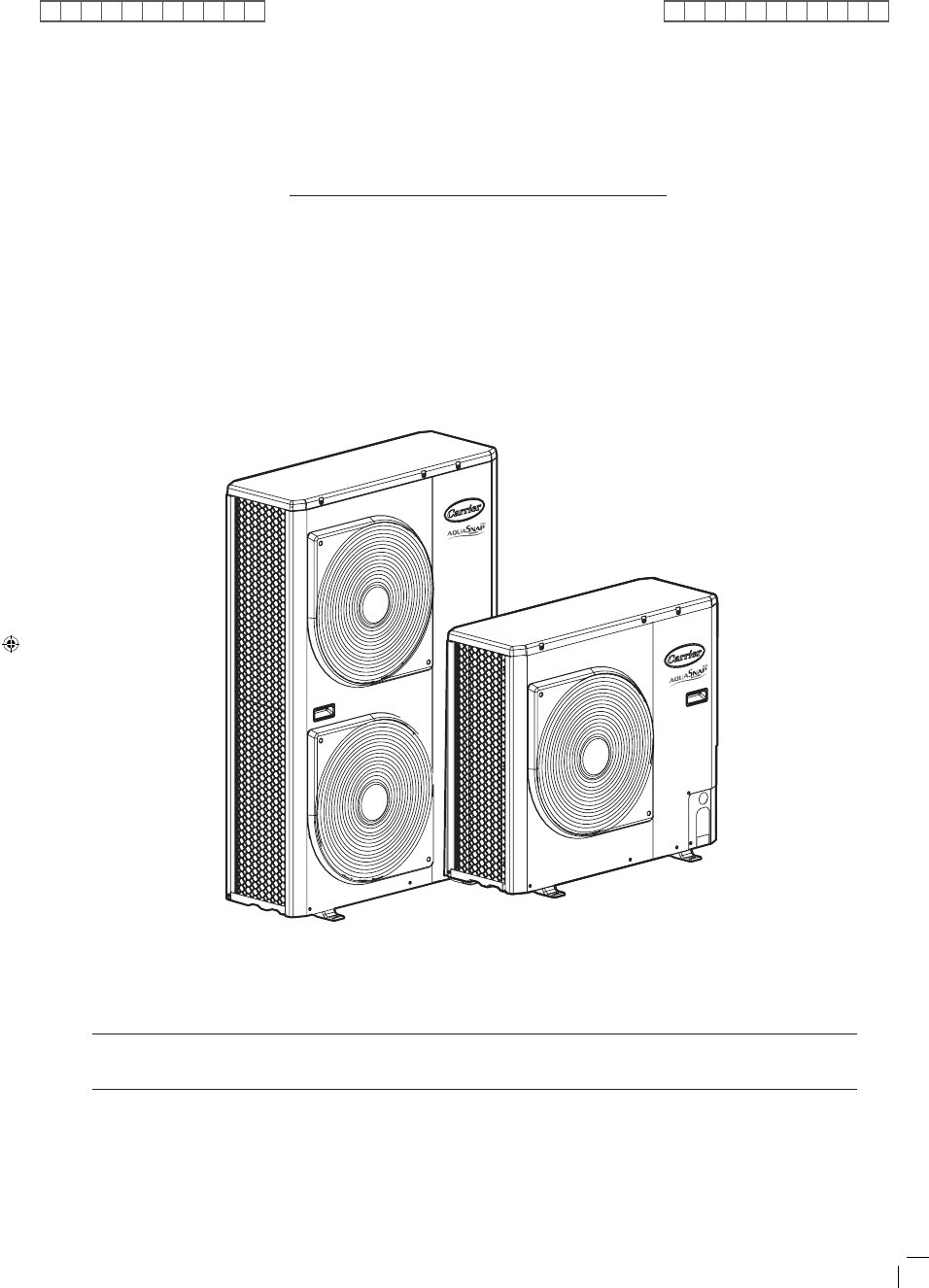
Carrier 30AWH004HB / 30AWH006HB / 30AWH008HB / 30AWH012HB. Service Manual - page 1
SERVICE MANUAL
Engineering Department of Italy
November, 2010
30AWH004HB/30AWH006HB/30AWH008HB/30AWH012HB/30AWH015HB
30AWH004XB/30AWH006XB/30AWH008XB/30AWH012XB/30AWH015XB
30AWH004NX/30AWH006NX/30AWH008NX/30AWH012NX/30AWH015NX
14-03-2011 14:40:43