Yanmar marine engine 6LPA-STP2, 6LPA-STZP2. Manual - part 5
 

  Index      Engines     Yanmar marine engine 6LPA-STP2, 6LPA-STZP2 - service manual


Search            


Content   ..  3  4  5  6   ..


Yanmar marine engine 6LPA-STP2, 6LPA-STZP2. Manual - part 5


PRODUCT OVERVIEW

6LPA Series Operation Manual

19

12/05

Warning Devices

When a sensor detects a problem during operation, the indicator on the instrument panel 
will light and an alarm will sound. Indicators are located on the instrument panel, the alarm 
is located on the back of the panel. Under normal operating conditions, the indicators are 
off.

• Alarm (Buzzer): If a warning lamp illuminates, the alarm will sound. However, no alarm 

will sound when the battery charging lamp illuminates.

• Alarm (Buzzer) Stop Switch: When investigating the cause of an alarm, press the alarm 

(buzzer) stop switch. 

WARNING

The switch is used to shut the alarm off temporarily. Turn the alarm (buzzer) OFF when 
inspecting for cause. Inspect and repair the abnormality immediately. 

• Warning Indicators: When operation is normal, the warning indicators are OFF. If an 

abnormality is detected, the sensor will trigger the appropriate warning indicator to light.

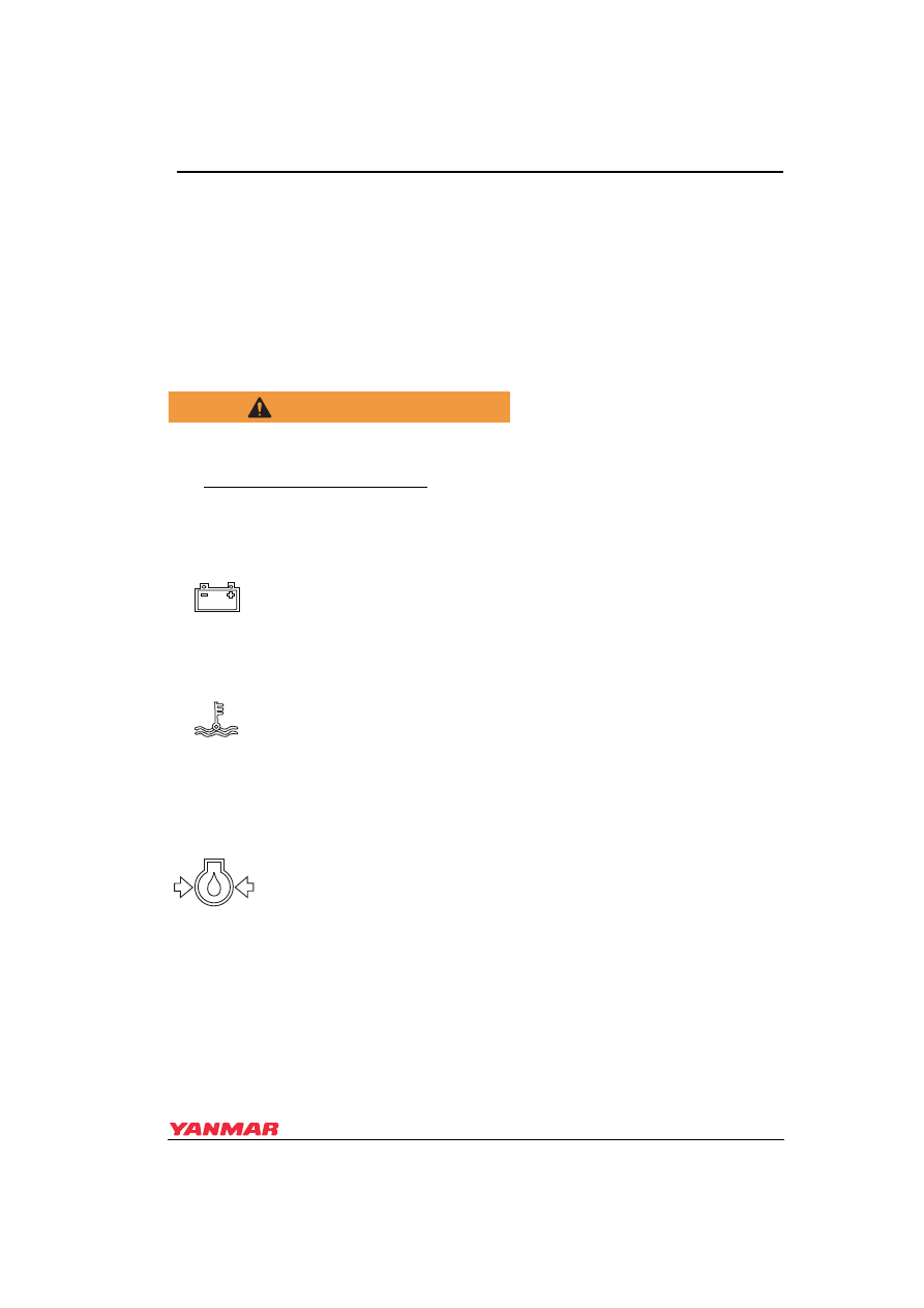
Battery Low Charge Indicator

When the alternator output is too low, the indicator will light. When 
charging begins, the indicator will turn off. No alarm will sound for low 
battery charge.

Fresh Water (Coolant) High Temperature Indicator and Alarm

When the coolant temperature reaches the maximum allowable 
temperature (95°C [203°F] or higher), the indicator will light and the alarm 
will sound. Continuing operation at temperatures exceeding the maximum 
limit will result in damage and seizure. Check the load and troubleshoot the 
fresh water cooling system.

Engine (Lube) Oil Low Pressure Indicator and Alarm 

When the engine oil pressure falls below the specified level, the oil 
pressure sensor will send a signal to the indicator causing it to light and the 
alarm to sound. Stop operation immediately to avoid damage to the 
engine. Check the oil level and troubleshoot the lubrication system.

PRODUCT OVERVIEW

20

6LPA Series Operation Manual

Alarms

Check that indicators and alarms are working normally when the key is turned to ON.

Fresh Water (Coolant) Level Indicator and Alarm

When the amount of cooling water in the fresh water recovery tank falls 
below normal, the sensor will send a signal to the indicator causing it to 
light and the alarm to sound. Stop operation immediately to avoid damage 
to the engine. Check the water level in the cooling water recovery tank and 
troubleshoot the cooling system.

Fuel Filter (Water Separator) 

When the water level inside the water separator becomes too high, the 
sensor will send a signal to the indicator causing it to light. Drain the water 
separator. If operation is continued without draining the water separator, 
fuel feed to the engine is restricted and may cause damage to the engine 
or fuel injection pump.

Exhaust (Cooling Seawater Flow) Restriction 

When the amount of cooling seawater being discharged is too low, the 
sensor will activate the warning indicator. Stop operation immediately to 
avoid damage to the engine. Check the seawater cooling system for 
restriction or damage.

Gear Oil Level (6LPA-STZP2 Only)

When the amount of gear oil falls below normal, the sensor will send a 
signal to the indicator causing it to light and the alarm to sound. Stop 
engine immediately to avoid damage to the gear device. Check the oil level 
in the gear and troubleshoot the gear system.

0004882

Key Switch

OFF ⇒ ON

START ⇒ ON

Engine

Before starting

Running

Alarm

ON

OFF

Indicators

Battery Low Charge Indicator

ON

OFF

Fresh Water (Coolant) High Temperature Indicator

OFF

OFF

Engine (Lube) Oil Low Pressure Indicator

ON

OFF

Fresh Water (Coolant) Level Indicator

OFF

OFF

Fuel Filter (Water Separator) Indicator

OFF

OFF

Exhaust (Cooling Seawater Flow) Restriction Indicator

ON

OFF

Gear Oil Level (6LPA-STZP2 Only)

OFF

OFF

PRODUCT OVERVIEW

6LPA Series Operation Manual

21

12/05

Key (Starter) Switch

 Figure 6

Figure 7 

The GLOW position (Figure 7, (1)) is the 
start aid position. Electric current to the air 
heater (if equipped) is turned on. 

The START position (Figure 7, (4)) allows 
current to the starting motor. When starting 
the engine, move the key to the START 
position and release. The key will 
automatically move to the ON position. 

NOTICE

NEVER hold the key in the START position 
for longer than 15 seconds or the starter 
motor will overheat.

When the key is in the OFF position 
(Figure 7, (2))

 the electric current is off. 

The key can be inserted or removed in this 
position.

The ON position (Figure 7, (3)) allows 
electrical current to the controls and 
equipment and allows the engine to keep 
running. To stop the engine, keep the key 
switch in the ON position and push the 
engine stop button. After stopping the 
engine, turn key to OFF position.

Engine Stop Button

 Figure 7

Figure 8 

Push and hold the stop button 
(Figure 8, (1))

 on the instrument panel to 

stop the engine. When the stop button is 
pushed, the solenoid valve on the fuel 
injection pumps stops the fuel supply to 
the engine. 

Press and hold the engine stop button until 
the engine has come to a complete stop. 

NOTICE

Releasing the engine stop button before 
the engine has stopped rotating will cause 
the engine to continue to run.

Remote Control (Throttle) Handle

The engine is controlled by the remote 
control handle located in the cockpit. The 
speed control lever on the engine and 
clutch lever on the marine drive are 
connected by remote control cables. There 
are various models of remote control 
handles available. When using a model 
other than shown below, consult the 
manufacturer's documentation for more 
information.

0003622

(1)

(2)

(3)

(4)

(1)

0004881

PRODUCT OVERVIEW

22

6LPA Series Operation Manual

Morse Remote Control Handle 
(Optional)

This is a single-lever remote control handle 
connected by a remote cable. It operates 
the clutch to NEUTRAL, FORWARD and 
REVERSE and controls the engine speed.

 Figure 8

MT-3 Top Mount

Figure 9           

1 – Reverse High Speed
2 – Reverse Low Speed
3 – Reverse
4 – Neutral
5 – Forward
6 – Forward Low Speed
7 – Forward High Speed

 Figure 9

MV Side Mount

Figure 10           

1 – Forward High Speed
2 – Forward Low Speed
3 – Forward
4 – Neutral
5 – Reverse
6 – Reverse Low Speed
7 – Reverse High Speed

The operation labels on the handle are:

• FWD - Forward

• NEU - Neutral (Clutch Disengaged)

• Throttle - Position to reduce engine 

speed

• REV - Reverse

Starting and Stopping

Put the handle in NEUTRAL. This puts the 
clutch in the disengaged position and the 
engine at a low speed.

Forward

Move the handle from NEUTRAL to FWD 
(forward). This engages the clutch in 
forward and simultaneously increases the 
engine speed. Pushing the handle further 
in the same direction increases engine 
speed to full speed.

(1)

(2)

(3)

(4)

(5)

(6)

(7)

0004886

(1)

(2)

(3)

(4)

(5)

(6)

(7)

0004887


Content   ..  3  4  5  6   ..