Technology of watch production - part 85
 

  Index      Books     Technology of watch production (Tarasov) 1964 year


Search            


Content   ..  83  84  85  86   ..


Technology of watch production - part 85


The  work spindle  revolves  at  3 5 0 0  rpm ,  and  the  peripheral  speed of the 

pinion  journals  is  therefore between  2  and  6 m

/

min,  which is  much smaller 

than  that or the wheel .  The  reversal  of the s ense  of rotation  of the  work 

spindle  therefore  only  slightly influences  the  resultant polishing speed. 

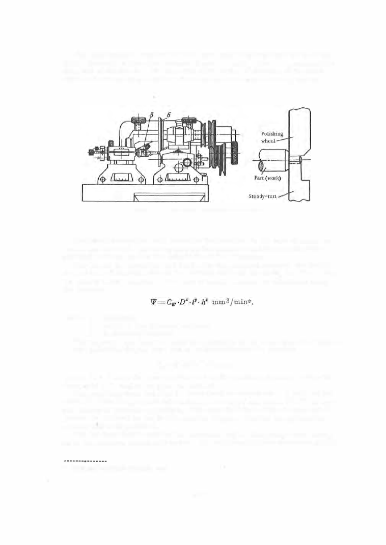
FIGURE 11.  Position of the work in the S-8a machine 

The basic  production- rate  index  for  the  machine  is  the  rate  of metal  re­

moval  (pe r  minute ),  which depends  on the diameter and the length  of the 

polished  surface,  and  on the  magnitude  of the  allowance .  

The  larger the  diam eter and  the  longe r  the polished surface ,   the large r 

the  surface  of contact between  the  carbide  ring  and  the  work,  and  the  higher 

the  rate  of metal  removal .  The  rate  of metal  removal  is calculated using 

the formula 

where 

diam eter; 

length  of the polished  s urface; 

diameter allowance; 

The  values  of the factor 

Cw 

and the  exponents 

x, 

y, 

are  given  in  Table 6 .  

The  polishing (basic )  time  can b e  calculated using the  formula 

TP 

Cr · D0 · lb · he 

min':' , 

where 

D,  l, 

have  the  same meaning as  in the  previous  fo rmula,  while  the 

exponents  a,  b,  and  c  are  given in Table  6 .  

The  polishing time  can also b e  taken from  the  s tandards .  A  table  o f  the 

polishing time  for  journals  with  0 . 0 1  mm  allowance  and  class  \l\7\TV 1 2  sur­

face finish  is  given  in Appendix  8.  The  spherical face of the balance  s taff 

journal  is  polished on  the  S - 1 3  3  machine  (Figure  1 2 )  after  the  cylindrical 

surface  has  been  polished. 

The  balance  staff  is held in the  headstock and on the  s teady - rest exactly 

as in  the  machine  considered above .  The polishing is performed by a carbide 

• 

Otgmashpribor Institute standards,  1954 . 

3 3 7  

pivot,  having on  its  lower working surface  teeth similar to  those  on  the 

wheel  of  the  S - 8a  machine .  The  teeth  on  the  front  part are  rough,  while 

those on the  rear  part  are  fine . 

TABLE  5 

Polishing-wheel cut as a function of the surface finish required 

Diamond grain size according to 

Surface-finish 

Polishing allow-

GOST 3647-47 

quality  class 

ance (on the dia-

Wheel cut 

for cutting cylin-

after polishing 

meter),  mm 

drical surface of 

for cutting face 

wheel 

of wheel 

10 

0.02- 0.05 

Coarse 

46 

120 

11 

0.01-0.02 

Medium 

60 

180 

12-13 

0.005 - 0.015 

Fine 

90 

220 

The balance  staff  revolves  at a  speed  between  2 140 and  4 2 3 5  rpm  and a 

reciprocating motion  is  all  the  while  imparted to  the  polishing pivot by the 

machine  link  motion  (Figure  1 3 ).  The  travel  is  20 m m .   The  numbe r  of 

s trokes  per  minute  is  1 3 0,  1 8 8 ,   or  2 5 8 .   The  working plane  of the  pivot  is 

in a  horizontal  position at the beginning of the  travel,  and  in a  vertical  posi­

tion at its end and the  polishing pivot thus  rotates  through  9 0°  from  the 

beginning to  the  end of its  travel  in  polishing the  spherical  face  of  the  staff . 

The  cycle  duration  is  3 . 5 - 5  s e c .  

TABLE  6 

Factors  and exponents for the determination of the rate of metal  removal 

and the polishing (basic) time 

Length of the surface 

Rate of metal removal, 

Polishing time, 

min 

mm3/min 

to be polished 

cw 

)I 

Cr 

l <  

0.7 

7 .5 

0.65 

0.5 

0.20 

0.35 

0.4 

0.5 

l >  

0 .7 

0.65 

0.4 

0.5 

0.25 

0.35 

0.6 

0.5 

The  electric m otor  ( 1 )  of the  S - 1 3  3  machine  (Figure  1 3 )  drives  the 

countershafts  I  and II  through  the  right and left-hand pulleys  and belt trans­

mis sions.  Countershaft  I  drives  the work spindle  through pulleys  ( 7 )  and 

(8).  The  link motion  (5) is  driven  through the  gear pair (2 - 3 )  and the  pol ­

ishing pivot  (6 )  is  connected  to  the  link motion.  C ountershaft II  drives  the 

camshaft III  through  a  worm  and  wheel .  The  camshaft carries  the  bell 

cam  (4 ),  which  controls  the  feed  of the  carriage  ( 1 1 )  by means  of the  rod ( 1 0 ) .  

The  carriage  moves  under the  rough and  the  fine  teeth  o f   the  polishing 

pivot alternately during one  cam shaft  revolution. 

Cam  ( 9 )  switche s  off  the  machine  after  one  cam shaft  revolution.  A fter 

polishing,  the  balance - s taff journal  is  buffed by means  of  a  paste made  o f  

7 5  parts  diamantine  and  2 5  parts beeswax.  The  surface finish achieved 
is  of class  1 3 .  

3 3 8  

FIGURE 12.  S-133 

journal-rounding  machine 

FIGURE  13. 

Kinematic diagram of the 

S-133 

machine 

3 3 9  

Technical data,  S-133 machine 

M aximum diameter of the  journal to be  polished,  mm  .  . 

0.2 

Maximum diameter of the  journal  to be polished,  mm 

0.05 

Maximum journal length,  mm 

.  .  .  .  .  .  .  .  .  .  .  .  .  .  .  . 

0.40 

Total length of the part,  mm 

.  .  .  .  .  .  .  .  .  .  .  •  . 

.  .  .  .  . 

2  to 1 0  

Spindle speed,  rpm  .  .  .  .  .  .  .  .  .  .  .  .  .  .  .  .  .  .  .  .  .  .  .  .  2140 to 4285 

Travel of polishing  pivot,  mm 

.  .  .  .  .  .  .  .  .  .  .  .  .  .  .  . 

20 

Number  of complete  pivot  strokes 

. . . . . . . . . • . . . . .  

130,  188,  258 

Electric  motor  .  .  .  .  .  .  .  .  .  .  .  .  .  .  .  .  .  .  .  .  .  .  .  .  .  .  . 

0.25 kw 

1500 rpm 

Polis hing  of  the  journals  and  s houlders  is  followed by inspection  of  the 

diameter and  the  distance  between shoulders by  the  same means  and using 

the  same  methods  as  were used for the  inspection  of the blanks  (see  Chap­

ter IV).  The surface-finish  quality is  visually inspected using a  magnifying 
glass  (5X )  or a  m icroscope  of magnification  1 6X  to  7 0X,  depending on  the 

dimensions  and  shape  of the surface inspected and on the surface - finish clas s .  

Polishing wheels  are  dressed on  the  S - 1 9 6  machine  (Figure  1 4 )  by means 

of two  diamond wheels . 

The  polishing wheel  is  fastened,  together  with  the  spindle ,   in  the  support 

( 3 )  mounted on  slides  which can move the polishing wheel  in  three  directions 

for adjustment.  Two  diamond wheels  dress  the  two  working surfaces  of the 

polishing wheel  consecutively  in the  same  chucking. 

The  kinematic  diagram  of the machine  is  given in  Figure  1 5 .   The  elec­

tric motor,  by means  of round belts,  drives  the  spindles for the diamond 

wheels  ( 1 )  and  (2 ) and for the  polishing  wheel being dres sed.  The  slide  can 

rotate  through  a  maximum angle of  1 1 0°  in  order  that  the  polishing wheel be 

dressed on the face and  cylindrical  surfaces  at various  angl e s .  

The  spindles  of the  diamond wheels  can  also  move  axially. 

Technical data,  S-196  machine 

Polishing-wheel diameter, 

mm 

.  .  .  .  .  .  .  .  .  .  .  .  .  . 

30-120 

Wheel width, 

mm 

.  .  .  .  .  .  .  .  .  .  .  .  .  .  .  .  •  •  . 

.  .  .  .  Up to 1 0  

Diamond-wheel diameter,  mm  . .  ,  .  .  .  .  .  .  .  .  .  .  .  . 

75 

Number  of diamond wheels  .  .  .  .  .  .  .  .  .  .  .  .  .  .  .  .  . 

Diamond-wheel speed,  rpm  .  .  .  .  .  .  .  .  .  .  .  .  .  .  .  .  . 

6000 

P

o

li

s

h

ing

-

w h

ee

spindle 

speed,  rpm  .  .  .  .  .  .  .  .  .  .  .  . 

900 

Angle of rotation of 

the 

slide, 

degrees 

.  .  .  .  .  .  .  .  . 

1 1 0  

Electric  motor 

• 

• 

• 

0.35 kw 

3000  rpm 

D i a m o n d   w h e e l s   a r e   widely used in  watch production for  dress ing, 

grinding and finish- grinding of carbide  tool s ,   polishing wheel s ,   punche s, 

die s ,   templates,  gage s ,   e tc .  

The  range  o f  use o f  diamond  wheels i s  given in  Table  7 .  

The  diamond  wheel i s  made  of  two  o r  three parts :  body,  base,  and 

diamond  layer  (see  Table  7 ,   ASh- 1 a ) .  

The bodies are made o f  aluminum  o r  steel .  Bakelite  mol ding powder 

and  cermet alloys  are  used for the base and for bonding the  diamond  grains .  

The  diamond  grains,  of  grain  size  strictly  specified,  are  distributed  homo­
geneously in the  matrix  (see Table  7 )

340 


Content   ..  83  84  85  86   ..