Technology of watch production - part 83
 

  Index      Books     Technology of watch production (Tarasov) 1964 year


Search            


Content   ..  81  82  83  84   ..


Technology of watch production - part 83


motion is  imparted to  the  funnel  body  by an  eccentric  shaft  driven  by pul ­

ley  (5 ),  and  by  the  spring of  the  supporting  center  (6 )  placed inside  the 

head  (7 ).  The  machine  head  ( 7 )  and  the  connecting arm  ( 3 )  are  fastened  to 
the  machine  bed. 

Pulley  (5)  revolves  at  145  rpm .  A  block is  filled in 0 . 5  to  2  minute s .  

A fter the  machine  has  stopped the  funnel  body i s  drawn back t o  the  left, 

released from pin  (4 ),  rotated  90°,  and the block removed.  The holes which 

remain  empty  are filled with  screws  manually. 

Shellac  or  rosin  is  then poured  onto  the block.  The  block  is  first heated 

on an  electric  heating plate  till the  shellac  (or  rosin )  melts ,  and  then  the 

s crews  are  pressed against  the block by  means  of a  press .  A fter the  blocks 

cool  down,  they are  mounted on the  S - 1 5  machine .  Fastening by means  of 

shellac  or  rosin causes  no  deformation  of the  parts . 

Tin+ antimony 

!}Jf6 

Cast  iron 

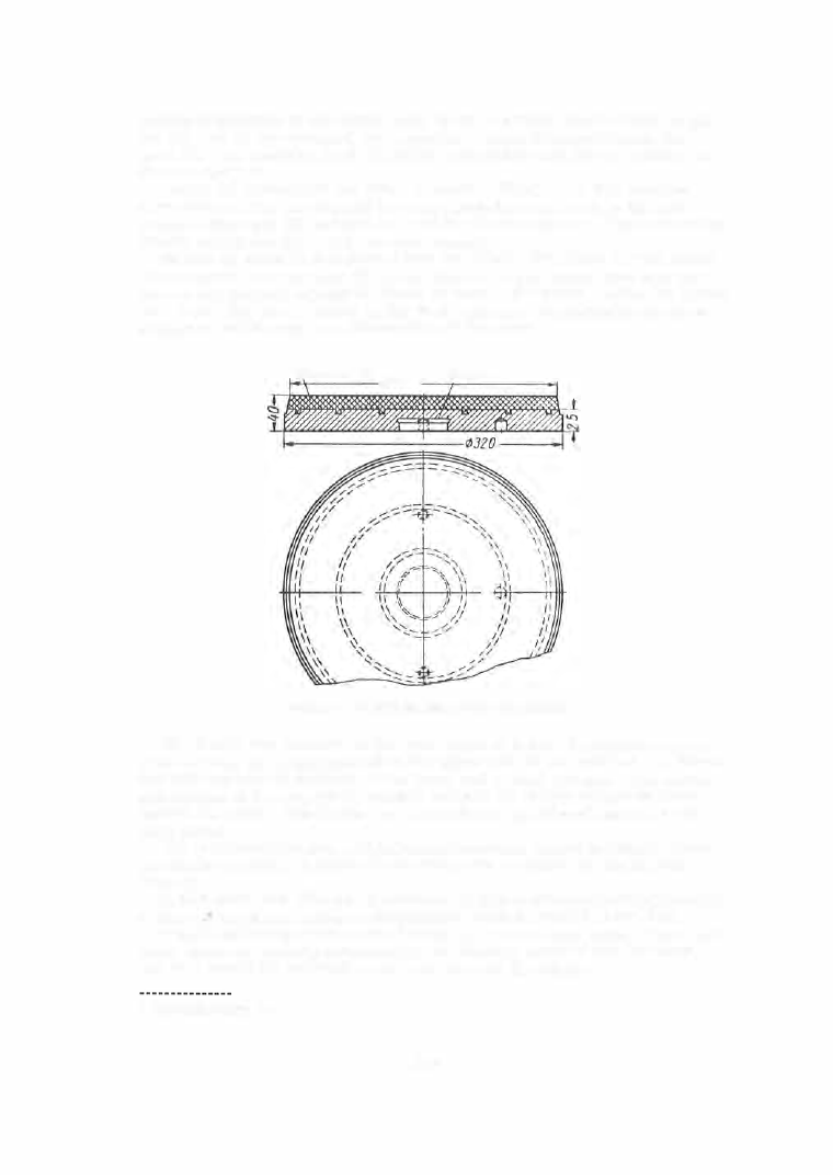
FIGURE  5.  Polishing disk used  in the S-15 machine 

The  blocks  are  mounted  on the  round  table  of  the  S - 1 5  machine  and  are 

pressed down by  weights  placed  on the  upper ends  of the  spindles .  A  driver 

bar with two pins  is  fastened  to  the  lower  end  of each  spindle .  The  conical 

extremities  of  the  pins  fit  the  central  holes  of the  blocks  and  press  them 

against  the  table .   The  blocks  are  automatically positioned  relative  t o  the 

table  plane . 

The  S - 1 5  machine  uses a  finish-faced  cast- iron disk  of  hardness  1 2 0  to 

1 5 0  HB  for lapping.  A  layer  of  abrasive paste  is  applied  to  the  lap  (see 

Table  2 ). 

A  disk made  of  a  9 9  o/o  tin 1 

o/o 

antimony alloy is used for polishing (Figure 5 ). 

A  layer  of chromium  oxide  or diamantine':'  paste is applied to the  disk. 

Wooden polishing disks made of beech o r  lime are also used.  Their flat ­

ness ,  however,  quickly  deteriorate s ,   the  block is  pres sed  into  the  wood, 

and  as  a  result the  polished parts have  burrs  at the  edges . 

•  [See Tab!e 2 , Sect.  3 . ]  

3 2 9  

The  weights  on  the  upper  end  of  the  spindle  transmit  the  required p re s ­

sure  t o  the  block during lapping.  One  weight i s  sufficient  in  polishing,  and 

it  can even be  dispensed with  since  the  weight of the  spindle  and  driver bar 
is  often  sufficient. 

Two  separate  machines ,  at a  distance  of  1  to  1 . 5 m  from  each other,  are 

used  for the lapping and  polishing operations  in order to  prevent abrasive 

grains  from  falling on  the  polishing disk.  The  blocks  mus t  be  carefully 

cleaned  of abrasives  and  washed in gasoline after  lapping.  Polishing is  as 

a  rule  performed in two  operations  (preliminary  and  final ).  The  lapping 
and  polishing paste s ,   and  the  materials  used for fastening the  parts  to  the 

blocks ,  are  selected in accordance with the  configuration of the  parts  (see 

Table  3 ). 

Shellac  ensures  a  stronge r bond between the  parts  and  the  block than 

does rosin  and  it is  therefore  used  for  pressures  of  2 . 0 kg

/

mm2  and above. 

TABLE  2 

Lapping  and polishing  pastes (compounds) 

Paste characteristics 

1 .   Emery paste (for lapping) 

Emery,  % 

. . . . . . . • . . . . . . • . . . . . . . • . . .  

Grain size (grit), 

I' 

. . • . • . . • . . • . . . . . . . . . .  

Stearin, 

o/a 

. . . . . . . . . . . . . . . . . . . . . . . .  

Lard, 

"/o 

. . . • • • • . . . . • • . • . • . . • • • • . • • • .  

Kerosene,  "/o 

•  •  .  .  .  •  .  •  .  •  .  •  •  .  .  .  .  .  •  .  .  .  •  .  . 

Surf ace-finish  class 

• 

.  .  .  • 

• 

.  .  .  .  •  . 

2.  Chromium-oxide paste (for polishing) 

Chromium-oxide, 

"/o 

. • . . . . • • . • . . . . . . • . •  

Grain size (grit), 

I' 

. . . . . . . • . • . . . • . . . . • . .  

Stearin, 

u/o 

. . . . . . . . . . . . . . . . . . . . . . . .  

Paraffin,  % 

. . . . . . . . . • . . . .  

· 

•  ·  • 

· 

.

.

 · 

·  ·  •  · 

Oleic acid,  % 

• . . . . . . . • . . • . . . . . . . . . • . .  

Graphite , 

"/o 

• • • . . . • . . • . • • . . . • • . . • . • • •  

Lard, % 

.

.

.

.

.

.

.

.

.

 · 

· 

· 

• 

· 

· 

· 

· 

• 

· 

•  ·  ·  •  ·  • 

· 

64 

M-28 

36 

8- 9 

67 

M-3.5 

13 

13 

0.2 

Industrial fats,  "/o 

•  •  .  •  •  •  •  •  •  .  .  .  •  .  •  •  .  .  .  •  .  • 

1 .8 

Kerosene, 

"/o 

.  .  •  .  .  .  .  .  .  .  .  .  .  .  .  .  •  .  .  .  •  .  .  .  . 

Surface-finish  class 

. . . • . . . . . . . . . . . . . . . . .  

11-12 

3.  Diamantine paste (for polishing) 

Diamantine ( leuco-sapphire or monocorundum), 

"/o . 

Grain size (grit), 

fl  . . . . . . . . . . . . . . . . . . . .  

Beeswax 

. • . . . . . . . • . . . . . • . . . • . • • . . . . .  

Surface-finish class 

. . • . . . . . . . . . • . . . . . . . •  

Paste type 

95 

M-20 

2.5 
2.5 

9-1 0  

6 0  

M-3.5 

20 

12-1 3  

66 

M-3.5 

29 

1 3  

75 

M- 3 .5 

25 

13-14 

Lapping and polishing conditions.  During  the  operation  of the  machine , 

when  the  table  and  spindles  revolve  s imultaneously,  the  block carrying the 

parts  performs  complex motions  relative  to  the  lap ,  as  a  result of which  a 

uniform  laye r  of metal  is  removed from  parts  both  near  and  far  from  the 

block cente r.  The lapping speed varies  between  0  and  3 m

sec . 

The  same  process  conditions are  used for lapping  and  polishing parts 

made  of different grades  of steel .  The  machining  (basic )  tim e  depends  on 

the  area  of the  parts  to be  machined and  on  the  allowance .   In practice ,   the 

3 3 0  

machining time  is  calculated  on  the  basis  of  standards  established in  the 

watch plant s .   A  table  for calculating  the  lapping time for steel parts  with 

0 . 02 mm  allowance  is  given  in Appendix  6 .   The  auxiliary  time  is  als o  deter­

mined on the  basis  of standards . 

TABLE  3 

Lapping  and polishing pastes (compounds) 

Pressure, k

g/

mm2 

Material used for 

Types of parts 

lapping 

polishing 

fastening the parts 

Lapping pastes 

Polishing pastes 

to the block 

Scre\YS, ratchets, 

1-2 

0-5 

Rosin 

Emery paste-

Chromium-oxide 

regulators,  caps, 

type A 

paste- type B 

etc. 

Escape wheels, 

2- 3 

0-5 

Shellac 

Emery paste -

Chromium-oxide 

pallet levers, 

type B 

paste-type B 

etc . 

An  allowance between  0 . 0 5  and  0 . 2 0  mm  is  fixed  for  (flat) surface lapping, 

and the  allowance  for  preliminary and final polishing is  between  0 . 0 1  and 

0 . 02 mm. 

The  deviations  in the  dimensions  of parts  polished  on the  S- 1 5  machine 

do not e xceed  0 . 0 1  to  0 . 02 mm,  and  therefore,  in certain cases no  particular 

allowance  is  established  for polishing and  the  decrease in  dimensions  is  at 

the  expense of the  final - dimension tolerance .  

The  operation o f  the  S - 1 5  machine i s  s tarted by  turning the handle  ( 2 3 )  

(see Figure  2 ).  This  lowers  the  spindles so  that  the  ends o f  the  driver-bar 

pins penetrate into the conical  recesses  in the work blocks  and press  the 

blocks  against the  table .   The  electric  m otor  is  then  s witched  on,  and  the 

spindles  and table  begin  to  rotate .  Paste  is  applied periodically by hand . 

A fter  the  lapping,  the  spindles are  lifted,  the  blocks  are  removed, 

cleaned of abrasive s ,   and the  height of the parts  is  measured by means  of 

a  dial gage.  If the  dimension is larger than  specified,  the blocks  are  again 

loaded into  the  machine,  and  the  parts  ar�  lapped  again. 

Surface-finish  quality after  lapping and polishing is inspected  visually 

using a  magnifying  glass  ( 5X).  A  microscope  ( 1 6X) is  used in some  cases . 

A fter  the polishing,  the block with the  finished parts  is  dismantled. 

Polishing P inion  Teeth 

A fter milling,  pinion teeth have  a  class  8  or  9  surface-finish  quality  which 

is  raised to  class  1 1  or  1 2  by polishing. 

The  pinion teeth,  which have  a  hardnes s  of  52  to  5 5 HRc after hardening, 

are polished on the  S- 5  (Figure  6 )  or  the  S- 83  machine  with type A  chromium 

oxide  applied to  the  beech disk on  the  machine . 

The  polishing disk ( 1 )  of  the  S - 5  machine i s  m ounted  on  the  spindle  ( 2 )  

o f  the  rocker arm  ( 3  ).  The  pinion i s  freely placed o n  its  journals o r  pro­

j ections in the  steady- rest  (4 ),  which is held between centers on the heads ( 5 )  

mounted o n  slide  ( 6  ) .  

3 3 1  

The  polishing disk  has  a  spiral  flute  along  its  circumference .  When  the 

rocker arm  is  lowered,  the  flute  meshes with the  pinion teeth and  the  pinion 

rotates  about its  axis  as  the  disk rotates .   If the  length  of the  teeth  is  more 

than 2 mm,  a  reciprocating motion is  imparted to  slide  (6 ) by the  connecting 

rod  ( 7 )  and  the  crank  ( 8 ) .   A  belt is  slipped over pulleys  ( 9 )  and  ( 1 0 )  to pro­

vide power for the reciprocating motion . 

The  inserts  for  the  steady- rest are  made  of carbide  and  are  brazed to 

the  rest with  copper 

(

Figure  7 ) .  

The  beech polishing disk wears  rapidly.  The  flutes i n  the  disk are  cut 

directly on  the  machine and,  for this purpose,  the  slide  with  table  is  rotated 

by  5  to  6 ° .   The  disks  are  made o f  a  single  piece of wood without knots  or 

any other flaws.  Disks  made of an 87 o/o  lead,  4 o/o  tin and  9 o/o antimony alloy 
are  more  wear-resistant,  and  in addition give a  better - quality polish. 

Technical data,  S-5 machine 

Polishing rate,  m/sec  .  .  .  .  .  .  .  .  .  .  .  .  .  .  .  .  .  .  . 

4- 7 

Maximum pinion diameter,  mm  .  .  .  .  .  .  .  .  .  .  .  . 

30 

Maximum module,  mm 

• 

.  .  .  .  .  .  .  .  .  .  • 

.  .  • 

Polishing-disk diameter,  mm 

.  .  •  .  .  .  • 

• 

•  • 

7Q- 150 

Polishing-disk spindle speed,  rpm  . 

.  .  .  •  •  .  .  .  • 

750 

Number of strokes of part  slide per minute  . 

•  •  • 

• 

113 

Maximum spindle travel,  mm 

•  .  .  .  •  •  •  •  •  •  • 

.  . 

22 

FIGURE 6 .   S-5 pinion-tooth polishing machine 

3 3 2  


Content   ..  81  82  83  84   ..