Technology of watch production - part 31
 

  Index      Books     Technology of watch production (Tarasov) 1964 year


Search            


Content   ..  29  30  31  32   ..


Technology of watch production - part 31


inc reas es  considerably,  this  being detrimental  to  the  surface-finish  quality . 

It should  be  noted  that  the  cros s - s e ctional  a rea  of  the  chip  is  small  when 

m achining  watch parts ,  and  the refore  the  depth  of  cut is  usually not taken 

into  account  when  establishing the  cutting conditions . 

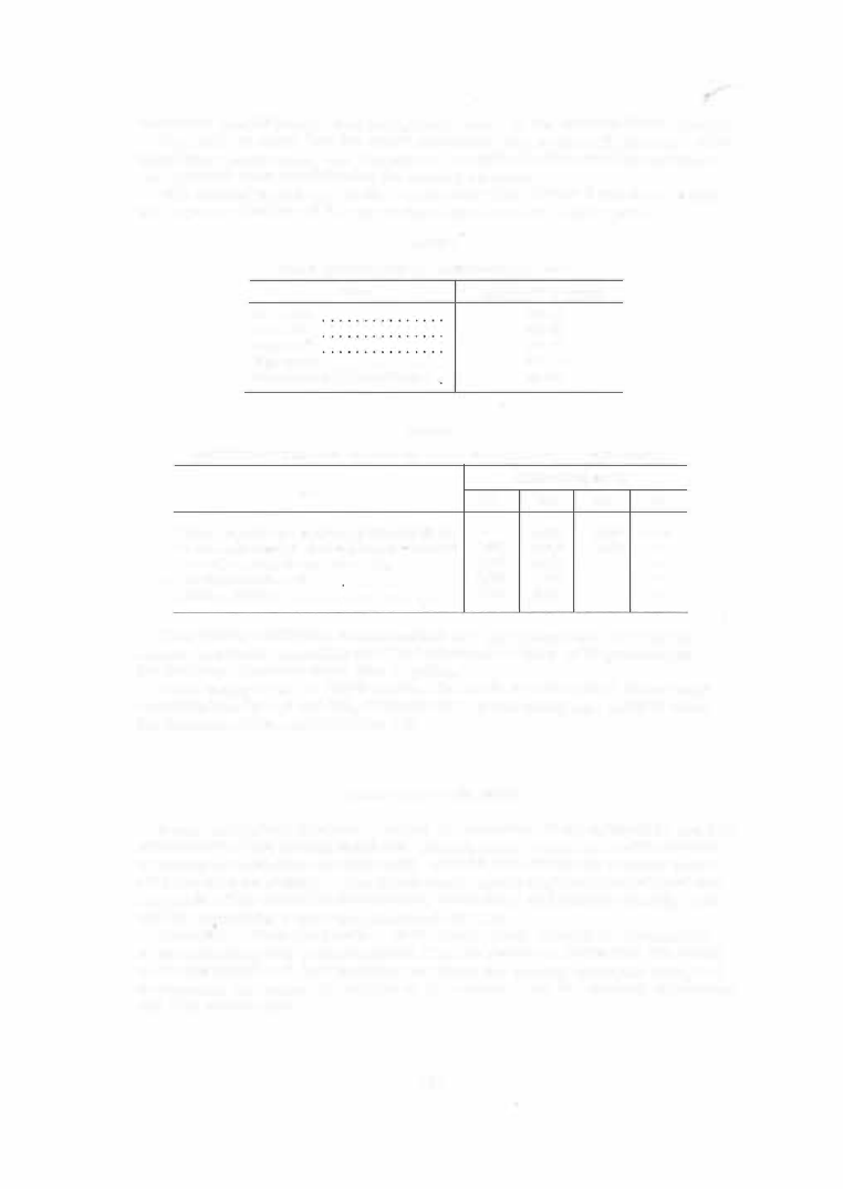
The  cutting  speeds  and  feeds  recommended  in  Tables  4  and 

are bas ed 

on  a  sys temati zation  of the up - to - date  experience of watch plants . 

TABLE  4 

Cutting speeds  on Swiss-type  automatic  screw  machines 

Steel  UlOA 
Steel U7A V 
Steel El699 

Metal 

Brass LS63-3  . . . . . . . . . . . . .  . 

German silver MNTsS63-17-18-2 

TABLE  5 

Cutting speed,  m/min 

2 0-40 
2 0-60 

1 5- 30 

30- 1 00 
3 0-60 

Feeds  for  U7A V steel worked on Swiss-tyjle  automatic screw  machines,  mm/revolution 

Process 

Turning  journals  and  chamfering  pinions  and  shafts 

Turning  cylindrical,  conical  and contoured surfaces 

Cut-off, 

plunging,  facing  and recessing 

0

.

 0 

 0 

Turning nonworking surfaces 

 0 


Drilling,  centering 

• 

 0 


7th 

-

0.015 

0.008 

0.02 0  

0.015 

Surface-finish  quality 

8th 

9th 

l Oth 

0 .01 0 

0.008 

0 . 005 

0.010 

0.008 

-

0.005 

-

-

0 .015 

-

-

0 .01 0 

-

-

The  cutting conditions  recommended are  not  optimal  and  the  cutting 

speeds  and feeds  can and  should be increas ed as  s oon  as  improvements  in 

the  limiting elements  make  this  feas ibl e .  

When using U 1 0A  o r  EI6 9 9  s teel s ,   the  feeds  recommended  above  must 

be multiplied by  0 . 9  and 0 . 8 ,  respectively.  When using  type  LS6 3 - 3  brass 
the feed s hould  be  multiplied by  1 . 2 .  

CALCULATION  OF  THE  SETUP 

Setup  calculation involves  planning the  s equence  of all operations  and  idl e 

movements  of  the  cutting  tools  and  working parts  of  the  automatic  machine 

(allowing  for possible overlappings ),  and  the  es tablishment  of dwell inter­
vals  between  operations .  The  s etup  must ensure  that  the  finis hed part  cor­

responds  to  the  specified  dimensions ,  tole rances  and s urfac e  quality,  and 

that its  machining  requires  a  minimum  of tim e .  

I n  order t o  d raw  the  p rofiles  o f  the  cams  which  control  all  the  motions 

of the  working parts  of the machine,  it is  necess ary  to  determine  the  values 
of the  headstock and  tool motions ,  to  s elect the  cutting speed and  feed,  and 

to  calculate  the  angles  of rotation of the  camshaft  for the  various  operations 

and  idle  movem ents . 

1 2 1  

The  cam  curves  are determined by  two  parameters :  1 )   the  value  o f  the 

central  angle  corresponding  to the  angle of rotation of the  camshaft  during 

the  time  of the  operation  or the  idle movement;  and  2 )   the  value  o f  the  in­

crement  (or  decrement)  of cam  radius  (the  value  of the  linear displacement 
of the  given working part  of the  machine ) .  

The  cam  curves  are  c alculated  so a s  to  complete  the  entire  cycle  of 

operations  and l.dle movements  and  to  completely machine one part  in  one 

camshaft  revolution.  Sometimes  2  to  3  parts  are  completed  during  one 

revolution of the  camshaft,  as  in  the  case of the p art  shown  in  Figure  2 6 .  

The  machining o f  this  part is  simpl e .   The b a r  already has  the  specified 

diameter and  the only operations  carried out on the  machine  a re  the  cham-

FIGURE 26. 

W ristwatch bridge pin 

fering  of both  ends  and  the  cut- off. 

Three  cycles  are  completed,  and there ­

fore  three parts p roduced,  for one  cam ­

s haft  revolution. 

The  cam  ris e  for  the  operations  and 

the  idle  movements  depends  on the  ratio 

of lever arms  s elected.  This  ratio 

varies  within  certain  limits  for  the  head­

stock and  for  the  rocker,  while  for the 

other  mechanisms  it  is  a  c onstant  mag­

nitude  (see Table  6 ). 

Two  headstock cams  and  three  rocker 

cams  can be mounted on the camshaft.  Several  cams  are installed in order 
to  speed up the process  of  changing over from machining one part  to machin­

ing another .   A side from  this ,  in  complex s etups  the p rofile of the  cam  curve 

for  s ome  operations  is  split up into two  or  three p rofiles ,   thus  creating the 

possibility  of increasing the  accuracy  of  the  cams . 

The  travel  of  the  headstock o r  the  tool  is  defined as  the  difference be­

tween its  initial  and  final pos itions .  Thus ,  the  value  of the  heads tock travel 

will be  equal  to  the  length of the p art plus  the width of the  cut- off tool . 

The  travel  of  cutters  No . 2  (or  1 ),  3 ,  4 ,   5  is  determined by the  formula 

C  D - d  

s =   + 

where 

distance  from  the  initial  cutter position to  the  bar; 

= bar diameter 

machined diameter 

= tool  cross - ove r. 

( 3 )  

The  distance 

(at cut - off) is  usually  0 . 5  m m  when machining bars  of 

3 mm diameter and up .  When bars of s maller diameter are  machined the 

cutters  must be s et  at a  distanc e  of 2 mm  from  the  bar axis  in order to 

make  sure of the  free  approach  of the  cutters  in working position and the 

free  passage  of the bar between the  cutters .  The  value of 

is  0 . 1  to 0 . 2  m m .  

Having determined the  heads tock or tool  travel,  the  c am  ris e  or drop is 

determined,  taking into  account the ratio  of the lever arms .  Thus ,  if the 
part length is  3 . 2 5  m m ,   the  width of the  cut- off tool  0 . 2 5  mm and  the  ratio 

of  the  headstock  lever  arms  is  2 : 1 ,   the  stock-feed  cam  rise  will  be: 

( 3 . 2 5  + 0 . 2 5 )2 

7 m m .  

1 2 2  

The  maximum heads tock lever ratio  (3: 1 )  is  s el ected to  m1mmize  the 

influence  of  errors  in  the  cam  profile  in  those cas es  where a narrow toler­

ance must b e  held on axial  dimensions .  It must be kept in mind that  accord­

ing to  the  design data the maximum  allowable  cam  ris e  is  5 0  mm. 

The  2 : 1  lever ratio  is  recommended f o r  the manufacture o f  long parts , 

s ince  the  ris e  curve  co rresponding to  the  3 : 1  ratio  is  s teep,  especially for 

small  radii,  and jamming of the  cam could occur. 

TABLE  6 

Lever  arm  ratios  and  cam  dimensions  for  the  1A10P automatic  screw  machine 

Displacement mechanism 

Headstock feed 

 0 

Rocker 

.

.

.

.

.

.

.

.

.

.

.

.

.

.

.

.

.

.

.


Tool slide No.  3  feed 

.

.

.

.

.

. .

.

.

Tool  slide  No.  4  feed 

 0

.


0

.


Tool slide No.  5  feed 


Centering-drilling attachment spindle 

feed 

 0 


Drilling-threading  attachment spindle 

feed 

0

.


S lotting  attachment  lever  feed 

.

.

.

Lever  arm 

ratio 

F l a t  

c a m s  

from  1 : 1  

to  3 : 1  

3 ; 1  

and 

1 0 : 1 

1 : 1 

2 : 1  

2 : 1  

B e l l  

c a m s  

1 : 1  

1 : 1  

1 : 1 

Basic  cam  dimensions,  mm 

cam thick-

dtameter  meter 

ness 

160 

60 

2 0A 

120 

70 

2 0A 

120 

70 

28A 

120 

7 0 

28A 

120 

7 0  

28A 

cam  height 

88 

24 

22 

1 00 

86 

42 

100 

86 

21 

The motions  of the working parts  of the automatic  machine  can be clas ­

sified  as  motions  directly  connected  with  the  m achining of  the  bar,  and 
motions  not directly  connected with m achining.  Motions  of the  first  type 

are  called o p e r a t i o n s;  motions  of the  second type - i d l e  m o v e m e n t s . 

Calculation of  the  idle movements .  When blanks  of  watch parts  are 

machined on Swiss - type  automatic  screw machines ,  from  15  to  2 5 o/o  ( 3 5 o/o 
in some cases )  of  the  cycle  time  is  taken up  by  idle movements  which,  ob­

viously,  s hould be kept at a  minimum  value  in  order to  increas e  the produc ­
tivity  of  the  machine . 

Som e  examples  of idle  movements  are:  releasing the  collet,  retracting 

the  headstock,  closing  the  collet,  the  approach and  retreat of the  tools , 

dwells,  headstock advance when no  external  turning is  necess ary o r  when 

the  bar  is  fed  for  chasing,  etc . 

It  is  usual  to  express idle  movements  by  the  number of degrees  corre­

sponding to a  1 m m  ris e  o r  drop on the  cam . 

The  number of  degrees  corresponding to  1 mm  idle  ris e  or  d rop  for the 

same tool is  a  variable  magnitude  and  depends  on the production  rate of the 

m achine  for the  given part. 

1 2 3 

The  higher the  production  rate,  the  more  degrees  are  apportioned per 

mm idle movement. 

When the production rate is  low  (up  to  6  pieces  per minute ),  the inertia 

forces  on the  moving parts  of the machine are small  and  have  no  influence 
on  the  work,  and  can  the refore be neglected.  When the  production  rate  is 

high  (2 5  pieces  p e r  minute  and  more),  the inertia forces  become  consider­

abl e ,  and if the idle movement curves are incorrectly calculated,  the operation 
of the machine  can be  disturbed.  Let us  assum e  that the inertia forces  in 

the  lever driven by  a  cam  follower (Figure  2 7 )  are  quite  considerable  and 
exceed the tension of the lever spring.  In that case the  follower,  on  reach­

ing the  top point on the  cam p rofile ,   will  c ontinue  to  ris e  b ecause of inertia 
to  some height h and in coming down will  strike  the  cam .  To  avoid this , 

the  ris e  curve  must b e  made less  steep  or,  in  other words ,  the  number of 

degrees  per  m m   ris e  must b e  increas ed and the follower velocity at the 

end of the  rise  must be  reduced to  zero. 

FIGURE 27.  Headstock feed cam 

The  number of  cam  degrees  apportioned to  the idle m ovements  is  c.stab­

lished  on  the basis  of  the  m achine production rate,  taking  into  account the 

dynamic phenomena  occurring at high  camshaft  speeds . 

The  optimal  idle movements ,  in  degrees ,  for the  headstock and  rocker 

cam s ,   who s e  operation bas ically determines  the pro duction rate of the 

s crew m achine,  are given in  Tables  7 - 1 4 .  

I t  can b e  s een from  the tables  that the  cam  angle  apportioned t o  idle 

movements  increas es  with a  decreas e  in  cam  radius .  The  reason for this 
is  that a  small  rotation angle  at s m all  radii  gives  a  very  s teep  ris e  curve, 

which l eads  to rapid cam  and follower wear and possibly,  as  was  mentioned 

earlier,  to  j am ming of the  cam . 

1 24 


Content   ..  29  30  31  32   ..