Military reference books and manuals (2009-2023, Volume 7) - page 6
DISTRIBUTION AUTHORIZED TO U.S. GOVERNMENT AGENCIES AND THEIR CONTRACTORS
869
870
4
(U) SUMMARY
871
The current environment has inherent deficiencies that can be corrected by
872
implementing enterprise-wide information services. Implementing an enterprise email
873
service with over 5 million users extending across the DoD enterprise from the
874
sustaining base to the tactical edge is a massive undertaking. Executive leadership is
875
committed to the challenge and has provided direction to move forward with Spiral 1 of
876
the implementation of an enterprise email service. Implementation involves an
877
aggressive timeline. The Spiral 1 implementation will be closely followed by Army
878
leadership and will assist in making a decision for an expanded implantation of EMCS.
879
The CONOPS described in this document is needed to guide the consolidation of the
880
many current email systems into a single enterprise email service, that when
881
implemented, will deliver high mission value. In summary, Army EMCS:
882
Improves mission effectiveness by providing seamless messaging capabilities
883
built upon common, standard, and unified enterprise services.
884
Improves security by eliminating the vulnerability among the many disparate
885
domain mail systems.
886
Produces large cost savings by providing a unified solution that consolidates and
887
streamlines email implementation and administration across the Army
888
enterprise.
DISTRIBUTION AUTHORIZED TO U.S. GOVERNMENT AGENCIES AND THEIR CONTRACTORS
27
DISTRIBUTION AUTHORIZED TO U.S. GOVERNMENT AGENCIES AND THEIR CONTRACTORS
APPENDIX A - (U) ACRONYMS
(U) This appendix is UNCLASSIFIED.
CONOPS
Concept of Operations
CONUS
Continental United States
COOP
Continuity of Operations Plans
DoD
Department of Defense
EA
Executive Agent
EMCS
Enterprise Email Service
EMCSD
Enterprise Email Service Desk
FOC
Full Operational Capability
FY
Fiscal Year
GAL
Global Address List
GIG
Global Information Infrastructure
IC
Intelligence Community
IOC
Initial Operational Capability
JP
Joint Publications
JWICS
Joint Worldwide Intelligence Communications System
NIPRNET
Unclassified but Sensitive Internet Protocol Router Network
NSA
National Security Agency
OCONUS
Outside Continental United States
PKI
Public Key Infrastructure
RMC
Rate Management Council
SIPRNET
Secret Internet Protocol Router Network
US
United States of America
VPN
Virtual Private Network
WAN
Wide Area Network
DISTRIBUTION AUTHORIZED TO U.S. GOVERNMENT AGENCIES AND THEIR CONTRACTORS
A-1
DISTRIBUTION AUTHORIZED TO U.S. GOVERNMENT AGENCIES AND THEIR CONTRACTORS
APPENDIX B - (U) GLOSSARY
(U) This appendix is UNCLASSIFIED.
Architecture: the structure of components, their relationships, and the principles
and guidelines governing their design and evolution over time. [DoD Integrated
Architecture Panel, 1995, based on IEEE STD 610.12]
Cyber Attack: is the use of computers and the Internet in conducting warfare in
cyberspace. [WEB]
Cyberspace: A global organization within the information environment
consisting of the interdependent network of information technology
infrastructures, including the Internet, telecommunications networks, computer
systems, and embedded processors and controllers. [Joint Publication 1-02,
DOD Dictionary of Military and Associated Terms]
Data Center: A facility used to house computer systems and associated
components, such as telecommunications and storage systems. It generally
includes redundant or backup power supplies, redundant data communications
connections, environmental controls (e.g., air conditioning, fire suppression) and
security devices. [WEB]
Deployment: The relocation of forces and materiel to desired operational areas.
Deployment encompasses all activities from origin or home station through
destination, specifically including intra-continental United States, intertheater, and
intratheater movement legs, staging, and holding areas. See also deployment
order; deployment planning; prepare to deploy order. [Joint Publication 1-02]
Distribution List: A facility in electronic mail systems to enable a large number
of subscriber mail addresses to be reached through a single (list) name. [WEB]
Organization: A organization is the main subdivision of internet addresses, the
last three letters after the final dot, that indicate an organizational affiliation.
Some top-level organizations widely used are: .com (commercial) .edu
(educational), .net (network operations), .gov (US government), .mil (US military)
and .org (organization). [WEB]
Organization Name: The unique name that identifies an Internet site.
Organization Names always have 2 or more parts, separated by dots. The part
on the left is the most specific, and the part on the right is the most general. A
given machine may have more than one Organization Name but a given
Organization Name points to only one machine. [WEB]
Email: Mail composed and transmitted on a computer system or network.
[WEB]
DISTRIBUTION AUTHORIZED TO U.S. GOVERNMENT AGENCIES AND THEIR CONTRACTORS
B-1
DISTRIBUTION AUTHORIZED TO U.S. GOVERNMENT AGENCIES AND THEIR CONTRACTORS
Enterprise:
o A unit of economic organization or activity; especially: a business
organization. [WEB]
o For the purposes of the DoD/Intelligence Community AATT, the enterprise
consists of the Intelligence Community, DoD, and their partners. [AATT,
24 June 08]
Environment: Aggregate of external procedures, conditions, and objects
affecting the development, operation, and maintenance of an IS. [CNSSI-4009]
File Attachment: A binary file attached to a text message (e.g., word document
file, PowerPoint file, excel spreadsheet file, picture file). [WEB]
Identity Management: The act of registering identities and issuing, maintaining,
and revoking globally unambiguous, assured identifiers for human and non-
human subjects (e.g., individuals, organizations, work roles, COIs, devices, and
automated processes). Identity management is performed in a federated
manner. Subjects will exchange and must reliably interpret federated identifiers;
therefore, identifiers must be defined and communicated according to open
standards. Identity Management is fundamentally integrated with Credential
Management, the ESM capability where identity proofing is performed. [ESM]
Global Address List: A directory that contains entries for every group, user,
and contact within an organization's implementation of email. [WEB]
Global Information Grid: The globally interconnected, end-to-end set of
information capabilities, associated processes and personnel for collecting,
processing, storing, disseminating, and managing information on demand to
warfighters, policy makers, and support personnel. The Global Information Grid
includes owned and leased communications and computing systems and
services, software (including applications), data, security services, other
associated services and National Security Systems. Also called GIG. See also
grid; information.
[Joint Publication 1-02]
Node: In communications and computer systems, the physical location that
provides terminating, switching, and gateway access services to support
information exchange. [Joint Publication 1-02]
Provisioning: The process of providing users with accounts, the appropriate
access to those accounts, all the rights associated with those accounts, and all of
the resources necessary to manage the accounts. [WEB]
Service: A mechanism to enable access to one or more capabilities. [AATT]
Tactical Edge: The environment in which US forces directly engage adversaries
(e.g., Iraq, Afghanistan).
Thick Client: A user computer that host applications (e.g., Outlook) using the
machines internal processing and storage capacity. [WEB]
DISTRIBUTION AUTHORIZED TO U.S. GOVERNMENT AGENCIES AND THEIR CONTRACTORS
B-2
DISTRIBUTION AUTHORIZED TO U.S. GOVERNMENT AGENCIES AND THEIR CONTRACTORS
User:
o A person, organization entity, or automated process that accesses a
system, whether authorized to do so or not. [RFC 2828]
o Individual or process authorized to access an IS. [CNSSI-4009]
o
(PKI) Individual defined, registered, and bound to a public key structure by
a certification authority. [CNSSI-4009]
VPN Connection: A network that uses a public telecommunication
infrastructure, such as the Internet, to provide remote offices or individual users
with secure access to their organization's network. [WEB]
WEB-browser: A software application that allows for the browsing of the World
Wide Web. [WEB]
Wide Area Network: a computer network that spans a large geographical area.
[WEB]
DISTRIBUTION AUTHORIZED TO U.S. GOVERNMENT AGENCIES AND THEIR CONTRACTORS
B-3
DISTRIBUTION AUTHORIZED TO U.S. GOVERNMENT AGENCIES AND THEIR CONTRACTORS
APPENDIX C - (U) REFERENCES
(U) This appendix is UNCLASSIFIED.
The 2004 Intelligence Reform and Terrorism Prevention Act (IRTPA)
The 9/11 Commission Report
Executive Order 13311, Homeland Security Information Sharing, July 29, 2003
Executive Order 13356, Strengthening the Sharing of Terrorism Information To
Protect Americans, August 27, 2004
Executive Order 13388, Further Strengthening the Sharing of Terrorism
Information to Protect Americans, October 25, 2005
The 2005 National Intelligence Strategy
National Security Strategy
Quadrennial Defense Review Report
DoD Directive (DoDD) 8500.01E, Information Assurance (IA), Issued October 24,
2002 and Certified Current as of April 23, 2007
DoD Instruction (DoDI) 8520, Public Key Infrastructure (PKI) and Public Key
Enabling (PKE), October 7, 2003
Assistant Secretary of Defense for Networks and Information Integration and
DoD Chief Information Officer and Associate Director of National Intelligence,
Chief Information Officer Memorandum, “Department of Defense (DoD) and
Intelligence Community (IC) Commitment to an Interoperable Services-Based
Environment,” July 13, 2007
The Director of ODNI’s 500 Day Plan for Integration and Collaboration
JP 3-0 Joint Operations (Available at
JP 6-0 Doctrine for Communications System Support to Joint Operations
(Available at http://www.dtic.mil/doctrine/jpcsystemsseriespubs.htm.)
Net-Centric Environment Joint Functional Concept (Available at
Net-Centric Operational Environment Joint Integrating Concept (Available at
Protection Joint Functional Concept (Available at
DISTRIBUTION AUTHORIZED TO U.S. GOVERNMENT AGENCIES AND THEIR CONTRACTORS
C-1
DISTRIBUTION AUTHORIZED TO U.S. GOVERNMENT AGENCIES AND THEIR CONTRACTORS
Military Support to Stabilization, Security, Transition, and Reconstruction
Operations Joint Operating Concept (Available at
Joint Command and Control Joint Functional Concept (Available at
Irregular Warfare Joint Operating Concept (Available at
Homeland Defense and Civil Support Operations Joint Operating Concept
(Available at http://www.dtic.mil/futurejointwarfare/joc.htm.)
DoD Enterprise Email Tiger Team (EETT) Requirements Specification, Version
1.1, 2 August 2008 (Available at https://www.intelink.gov/inteldocs/view)
DoD Enterprise Email Tiger Team (EETT) Report-out Brief, September 18, 2008
ONEmail Implementation Tiger Team Final Report
DISTRIBUTION AUTHORIZED TO U.S. GOVERNMENT AGENCIES AND THEIR CONTRACTORS
C-2
TC 31-20-2
Special Forces Handbook
for the Fingerprint Identification System
September 2008
DISTRIBUTION RESTRICTION: Distribution authorized to U.S. Government agencies and their contractors only to
protect technical or operational information from automatic dissemination under the International Exchange Program
or by other means. This determination was made on 29 August 2008. Other requests for this document must be referred
to Commander, United States Army John F. Kennedy Special Warfare Center and School, ATTN: AOJK-DTD-SF,
Fort Bragg, NC 28310-9610.
DESTRUCTION NOTICE: Destroy by any method that will prevent disclosure of contents or reconstruction of the
document.
FOREIGN DISCLOSURE RESTRICTION (FD 6): This publication has been reviewed by the product developers in
coordination with the United States Army John F. Kennedy Special Warfare Center and School foreign disclosure
authority. This product is releasable to students from foreign countries on a case-by-case basis only.
Headquarters, Department of the Army
This publication is available at
General Dennis J. Reimer Training and Doctrine
TC 31-20-2
Training Circular
Headquarters
Department of the Army
No. 31-20-2
Washington, DC, 30 September 2008
Special Forces Handbook
for the Fingerprint Identification System
Contents
Page
PREFACE
iv
Chapter 1
FINGERPRINTING
1-1
Introduction
1-1
Fingerprinting Basics
1-2
Lines
1-3
Patterns
1-5
Ridge Count
1-8
Fault Count
1-12
Chapter 2
TAKING A SET OF FINGERPRINTS
2-1
Overview
2-1
Necessary Materials
2-1
Techniques
2-6
Standard Numbering of the Fingers
2-10
Converting Fingerprint Data for Radio Transmission by Using the Brevity
Code
2-13
GLOSSARY
Glossary-1
REFERENCES
References-1
INDEX
Index-1
Distribution Restriction: Distribution authorized to U.S. Government agencies and their contractors only to
protect technical or operational information from automatic dissemination under the International Exchange
Program or by other means. This determination was made on 29 August 2008. Other requests for this document
must be referred to Commander, United States Army John F. Kennedy Special Warfare Center and School,
ATTN: AOJK-DTD-SF, Fort Bragg, NC 28310-9610.
Destruction Notice: Destroy by any method that will prevent disclosure of contents or reconstruction of the
document.
Foreign Disclosure Restriction (FD 6): This publication has been reviewed by the product developers in
coordination with the United States Army John F. Kennedy Special Warfare Center and School foreign disclosure
authority. This product is releasable to students from foreign countries on a case-by-case basis only.
i
Contents
Figures
Figure 1-1. Bifurcation
1-3
Figure 1-2. Divergence
1-3
Figure 1-3. Type lines - example 1
1-4
Figure 1-4. Type lines - example 2
1-4
Figure 1-5. Core, delta, and type lines
1-5
Figure 1-6. Arch
1-6
Figure 1-7. Tented arch
1-6
Figure 1-8. Loops
1-7
Figure 1-9. Whorls
1-8
Figure 1-10. Placement of the reference line
1-9
Figure 1-11. Ridge count (loop)
1-9
Figure 1-12. Ridge count (whorl)
1-10
Figure 1-13. Loop pattern, (normal), whorl pattern (normal), and whorl pattern
(mutilated)
1-10
Figure 1-14. Example of rare pattern where core and delta are the same
1-11
Figure 1-15. Fingerprint impressions
1-11
Figure 1-16. Types of faults
1-12
Figure 1-17. Template
1-13
Figure 1-18. Template positioning on loop, whorl, and loop
1-13
Figure 1-19. Sample fault count
1-15
Figure 1-20. Detailed fault count description
1-15
Figure 1-21. Lockpoint
1-18
Figure 2-1. Typical commercially available fingerprint identification kit
2-2
Figure 2-2. Commercially available compact fingerprint identification station
2-3
Figure 2-3. Commercially available inkless fingerprint kit
2-3
Figure 2-4. Examples of field-expedient inking material
2-3
Figure 2-5. Example of field-expedient fingerprint card
2-4
Figure 2-6. Examples of commercially available magnifiers
2-5
Figure 2-7. Examples of biometric equipment
2-6
Figure 2-8. Completing the roll of the finger from “awkward-to-comfortable” position
2-7
Figure 2-9. Completing the roll of the right thumb
2-8
Figure 2-10. Fingerprints taken with biometric equipment
2-8
Figure 2-11. Thumbprint taken with biometric equipment
2-9
Figure 2-12. Fingerprint taken with biometric equipment
2-9
Figure 2-13. Standard numbering of the fingers
2-10
Figure 2-14. Finger numbering when finger is missing
2-11
Figure 2-15. Finger numbering when an extra digit is present
2-11
Figure 2-16. Sample of SF 87A (Fingerprint Chart)
2-12
ii
TC 31-20-2
30 September 2008
Contents
Figure 2-17. Numerical brevity code
2-14
Figure 2-18. Pattern classification brevity code
2-14
Figure 2-19. Fault count brevity code
2-15
Figure 2-20. Miscellaneous brevity code
2-15
Figure 2-21. Brevity code format PRINT
2-16
Figure 2-22. Brevity code format PASTE
2-17
Figure 2-23. PRINT message
2-18
Figure 2-24. PASTE message
2-18
30 September 2008
TC 31-20-2
iii
Preface
This training circular (TC) provides a doctrinal framework for Special Forces (SF) personnel involved in
fingerprinting operations. It outlines the contribution of SF to the theater biometrics effort. SF personnel
recovery (PR) missions seek to achieve specific, well-defined, and often sensitive results of strategic or
operational significance.
PURPOSE
Fingerprinting is the most basic and universally recognized means of taking biometric data. This TC describes
how to take and read fingerprints and how to then place that information into standard message format for
transmission via frequency modulation or satellite communications radio or, if necessary, by telephonic means.
This TC forms the basis for providing common SF doctrine. This TC does not describe specific tactics,
techniques, and procedures (TTP) or cover the specific role that biometrics plays in SF operations. Specific
TTP type of information must be found in other publications or through the appropriate Biometric Fusion
Center.
SCOPE
SF routinely employ unconventional tactics and techniques while conducting operations unilaterally and with
indigenous assistance. The conduct of SF differs from conventional operations in the degree of political risk,
operational techniques, independence from friendly support, and dependence on detailed operational
intelligence and indigenous assets.
APPLICABILITY
This publication applies to the Active Army, the Army National Guard (ARNG)/Army National Guard of the
United States (ARNGUS), and the United States Army Reserve (USAR) unless otherwise stated.
ADMINISTRATIVE INFORMATION
Unless this publication states otherwise, masculine nouns and pronouns do not refer exclusively to men. The
proponent of this manual is the United States Army John F. Kennedy Special Warfare Center and School
(USAJFKSWCS). Submit comments and recommended changes to Commander, USAJFKSWCS, ATTN:
AOJK-DTD-SF, Fort Bragg, NC 28310-9610.
iv
TC 31-20-2
30 September 2008
Chapter 1
Fingerprinting
INTRODUCTION
1-1. Special Forces (SF) Soldiers use various biometric identification systems in SF operations. Biometric
applications are fundamental to a wide array of SF operational activities, including, but not limited to, the
growing field of SF sensitive site exploitation (SSE) and the range of unit protection activities. SSE
applications include the identification of enemy personnel and cell leaders in a counterinsurgency (COIN)
environment following tactical operations, particularly during direct action missions. Unit protection
applications include maintaining databases on the identities of both United States Government (USG) and
local national personnel. A routine example of protection applications for biometric data include the
requirement to maintain isolated personnel report (ISOPREP) cards, which are fundamental to personnel
recovery (PR) operations for the recovery of isolated, missing, detained, or captured (IMDC) personnel;
ISOPREP cards are essential for the authentication of the IMDC individual. Another example of the use of
biometric identification in SF operations is for positive identification of local national workers in a combat
environment at an SF tactical facility, such as at a firebase. Whether in a garrison or combat environment,
the collection, transmission, and storage of biometric data is a critical and common component of SF unit
operations.
1-2. The most common and reliable means of identifying a person through biometric means is by the
fingerprint identification system (FIS). Since 2001, SF has principally used technological (digital) means to
take and transmit fingerprints to an automated fingerprint identification system (AFIS). However, although
there are many technological capabilities to accomplish this task at the disposal of U.S. forces, it may not
always be feasible to use advanced technological means to take, transmit, and/or store fingerprint data.
Therefore, SF Soldiers—particularly the SF intelligence sergeants, military occupational specialty 18F—
must be familiar with both the traditional (manual) means of fingerprinting and with the modern (digital)
means available to Special Forces operational detachments (SFODs). Therefore, this TC covers both
manual fingerprinting systems and some of the current digital systems available to the SFOD.
1-3. Manual FISs are still required in a wide array of SF operations. For example, situations may arise
when digital FIS equipment or adequate power supply is inoperable, damaged, or not properly calibrated—
simply put, there are times when even the most advanced and useful technology fails. In addition, given
that the vast majority of SF operations are conducted “by, with, and through” indigenous forces, SF has a
requirement to train, assist, and advise host nation (HN) regular and/or irregular forces who require FISs,
but do not have advanced technological means. Likewise, even when digital FISs are available and the HN
assets are capable of using them, it may be impractical or unwise to hand over these instruments. An
example of this would be in an unconventional warfare environment; it may not be advisable to give digital
FIS equipment to an irregular asset. In such a case, it may be necessary for the SF Soldier to read
fingerprints from a paper provided by the asset. Some of the factors that must be considered before coming
to this conclusion include the following:
z
What is the classification restriction of the equipment and its capabilities?
z
What are the consequences to the irregular asset and the USG if the asset is caught with this
equipment?
z
How hard is it to replace this equipment if it is turned over to the asset?
z
Is there an available funding authority to procure the necessary equipment for indigenous
personnel?
z
Can the linkage of this equipment to the United States be avoided if necessary?
z
How likely is it that the equipment is available to anyone other than the United States?
30 September 2008
TC 31-20-2
1-1
Chapter 1
z
How likely is the discovery of this equipment and its capabilities to cause embarrassment to the
United States or its allies?
z
How difficult is it to maintain the equipment and is the asset capable of accomplishing that
maintenance without assistance?
z
Is there another alternative to accomplish the task without losing physical control over the
technical equipment?
z
With all of these factors taken into consideration, is there a nontechnical means to accomplish
the task which will reduce the various risks and is less resource intense?
1-4. In the event the irregular asset provides a set of prints on a plain piece of paper or other suitable
surface, the SF Soldier must be able to read, categorize, and format the prints in order to transmit them to
the AFIS for positive identification. The information in this TC is designed to enable SF Soldiers to
become familiar enough with the FIS to not only use the equipment and techniques, but also to train an
irregular asset to provide this service, such as when operating as part of an unconventional assisted
recovery team (UART) in a PR scenario. These are critical skills; in the case of a UART, the SF Soldier
accomplishing this task will have to be proficient enough in the FIS to successfully complete the
authentication of the IMDC individual.
1-5. This TC explains how to take a set of fingerprints, read the fingerprints manually (when necessary),
and transmit the results. Transmission includes the proper message format for transmitting FIS data over
radio when fully digital file transfer capability is not available.
FINGERPRINTING BASICS
1-6. Manual FISs are the most basic and are still an effective means of identification. For many years
fingerprinting was—and even in the United States sometimes still is—performed manually without the aid
of current technology. There remain dedicated assets within the USG (the Federal Bureau of Investigation
[FBI], for example) that can manually read fingerprints. Although technological mechanisms involving a
live scan of a fingerprint to the Biometric Fusion Center (BFC) are routinely capable of receiving and
validating the fingerprints in less than 10 minutes, even manual FIS validation can be relatively quick.
Under ideal conditions and with a clear set of fingerprints, the manual technique can take as little as 30
minutes when properly done. Even without a live scan device, fingerprints taken by a manual FIS may be
transmitted and analyzed using digital devices. Once captured, the fingerprint must be photographed and
scanned to send it over the portal or read and converted into a message format for transmittal over a tactical
radio or phone. This hybrid manual/digital approach offers added flexibility and a relatively rapid response
to the SFOD.
1-7. Traditionally, ink and paper are used to capture fingerprints. This method can be done on living and
deceased suspects. When traditional ink and cards are not available, field-expedient methods are applied.
Blank paper may be used in the absence of a fingerprint card—lined paper should be avoided. Substitutes
for ink can be lipstick, charcoal, camouflage paint, magic marker, and even blood.
1-8. Standard ink and the standard FBI applicant card (covered in Chapter 2) should be used whenever
possible. The FBI applicant card can be scanned and photographed as is for transmission to the BFC
because the FBI card is a known size and shape. Fingerprint cards from other countries require a scale in
the photograph or scan.
1-9. A metric scale should be in the photo or scan. Even if the scale is not metric, it gives the examiner a
reference. When there is no metric scale available to use, a common item to size the print must be included,
such as a dollar bill scanned with the print, to provide a reference.
1-10. Lifting a fingerprint is easiest when done from a smooth (nonporous) object. Semi-porous and
porous objects generally require chemicals; therefore, they must be sent to a lab for proper processing. If
the item cannot be removed, a photograph may be the only way to retrieve the fingerprint.
1-2
TC 31-20-2
30 September 2008
Fingerprinting
1-11. In the event a traditional latent print cannot be lifted and it is necessary to photograph the print, the
following are some of the keys to taking a quality photograph of a fingerprint:
z
Latent images need to be 1000 pixels per inch (ppi) and a file type of Joint Photographic Experts
Group (JPEG) 2000, Tagged Image File Format (TIFF), or bitmap (BMP). The image should not
be saved as a Portable Document Format (PDF) or regular JPEG.
z
A scale should always be included in the image—preferably metrics rather than inches. The
scale should lay flat on the same plane as the latent print for proper calibration. If the technician
reading the print cannot accurately calibrate for size, the AFIS search will be inaccurate.
z
When photographing, the camera should be mounted on a tripod and at a 90 degree angle so that
the lens is parallel to the latent print being photographed to prevent parallax distortion.
z
Since images can only be posted to the portal one at a time, each image should be labeled
beginning with a case number and then the image number so that multiple postings can be
associated with one case; for example, 07-101-2 = case #07-101, latent image 2.
z
One of the most common mistakes when powdering latent prints is to over-powder. Less powder
is usually better. A little more powder can be added if the print is too light. Too much powder,
however, can fill in the furrows and obscure the fine detail of a fingerprint.
z
The technician should not twist the fingerprint brush between his fingers when powdering (like
the actors do on television). This method reduces the control over the brushing motion and can
damage the print, as well as pull powder between the ridges into the furrows, reducing the
quality. It is best to start brushing lightly in an area and when ridge detail begins to appear, try to
brush with the ridge flow, not against it.
z
Sometimes multiple lifts of the same latent can be taken. This would be done, for example, when
it looks like there is too much powder. After one lift, the technician should try to “clean up” the
print by lightly brushing with the ridge flow and not adding more powder to the brush—it
should still have some powder on it from the previous “dusting,” and then take a second lift to
see if the quality improves. The technician must be sure to always clearly mark on the lift card if
multiple lifts are taken of the same latent so that if someone is identified, it does not look as if
they were identified to multiple latents when in fact it is just one. The technician should always
ensure a photograph is taken before attempting to “improve” a print in the event the attempt
results in irreparable damage to the quality of the print.
LINES
1-12. SF Soldiers must be capable of properly classifying a set of fingerprints. Proper classification
includes the correct identification of type lines, core, and delta of each print. Before pattern definition can
be understood or impressions classified, it is necessary to understand the meaning of a few technical terms
used in the FIS. A bifurcation is the forking or dividing of one line into two or more branches (Figure 1-1);
a divergence is the spreading apart of two lines that have been running parallel or nearly parallel (Figure 1-2).
Figure 1-1. Bifurcation
Figure 1-2. Divergence
30 September 2008
TC 31-20-2
1-3

Chapter 1
TYPE LINE
1-13. Type lines are the two innermost ridges that start parallel, diverge, and surround
(or tend to
surround) the pattern area. They are used to locate the delta. Type lines are not always continuous ridges.
In fact, they are more often found to be broken. When there is a definite break in a type line, the ridge
immediately outside of it is considered to be its continuation.
1-14. According to the narrow meaning of the words in fingerprint terminology, a single ridge may
bifurcate, but it may not diverge. Therefore, with one exception, the two forks of a bifurcation may never
constitute type lines. The exception is when the forks run parallel after bifurcating and then diverge. In
such a case, the two forks become the two innermost ridge lines required by the definition. In Figure 1-3,
the ridges marked T-T are the type lines; the ridges marked A-A are not the type lines because the forks of
the bifurcation do not run parallel to each other.
1-15. Angles are never formed by a single ridge but by the abutting of one ridge against another.
Therefore, an angular formation cannot be used as a type line. In Figure 1-4, ridges A and B join at an
angle, ridge B does not run parallel with ridge D, and ridge A does not diverge. Therefore, ridges C and D
are the type lines.
Figure 1-3. Type lines - example 1
Figure 1-4. Type lines - example 2
1-16. The pattern area is the part of a fingerprint impression within the type lines. This area is the only part
of the impression used in SF fingerprint interpretation and classification. It is present in all patterns. In
arches and tented arches, it is enough of the print to be able to classify the impression. Arches do not have
clearly defined pattern areas. In the pattern areas of loops and whorls, the cores and deltas appear.
CORE
1-17. The core is the innermost recurving ridge line of a fingerprint impression. It will normally be located
approximately in the center of the pattern.
DELTA
1-18. The delta is the first print characteristic located in front of and nearest to the divergence of the type
lines. This point may be represented by any print characteristic such as a fork, a ridge ending, a ridge
segment, or a curving ridge (Figure 1-5, page 1-5).
1-19. In the examples provided in Figure 1-5, C is the core, D is the delta, and T marks the type lines.
Soldiers must ensure they are looking at the ridge lines and not the printing surface. Normally, the ridge
lines will be darker than the printing surface, as they are in this TC.
1-4
TC 31-20-2
30 September 2008

Fingerprinting
Figure 1-5. Core, delta, and type lines
PATTERNS
1-20. In the FIS, there are three main fingerprint patterns: arches, loops, and whorls. Arches are further
divided into arches and tented arches. Loops are further subdivided into finger loops and thumb loops.
ARCH
1-21. In an arch, the ridges enter one side of the impression and tend to flow out the other side with a
gentle rise in the middle. There may be various ridge formations in the pattern. Arches do not have a core.
All ridges flow (or tend to flow) with a slight rise in the center from one side of the pattern to the other
without any ridges recurving to the side they entered. An arch is an easily identifiable print providing the
individual reading the print does not get confused between ridges that have bifurcations and an innermost
recurving ridge. The best way to determine the difference is by looking closely at the place where the ridge
starts what appears to be a recurve. When the ridges have sharp angles, they are either bifurcations or two
ridges running into each other; they are not a recurving ridge line. Figure 1-6, page 1-6, shows examples of
arch patterns.
1-22. In the tented arch, most of the ridges enter from one side of the impression and flow (or tend to flow)
out the other side, as in the arch. The key difference, however, is that the ridge or ridges at the center of the
impression have a definite upthrust, which can be compared to the center pole of a tent and from which this
pattern derives its name. There are no recurving ridges in a tented arch. Figure 1-7, page 1-6, shows
examples of tented arches.
Note: Arches and tented arches constitute about 5 percent of fingerprint patterns.
30 September 2008
TC 31-20-2
1-5

Chapter 1
Figure 1-6. Arch
Figure 1-7. Tented arch
1-6
TC 31-20-2
30 September 2008

Fingerprinting
LOOP
1-23. A loop is the type of pattern found on fingerprint impressions in which one or more of the ridges
enter the impression from either side, flow toward the center of the impression, recurve upon themselves,
and tend to exit on the same side of the impression from which they entered. Loops are the most common
type of fingerprint patterns, accounting for approximately
65 percent. Loops are divided into two
categories: finger loops and thumb loops. The type of loop is not determined by the digit where it appears.
Rather, the rule for determining whether a loop print is a finger loop or thumb loop is determined by the
direction of the open ends of the loop in direct relationship to the finger or thumb on which the print
appears. With a finger loop, the ridges enter the print from the side of impression toward the little finger,
form a loop, and depart the impression from the same side. With a thumb loop, the ridges enter the print
from the side of the impression toward the thumb, form a loop, and depart the impression on the same side.
Loops have only one core and one delta. Figure 1-8 shows examples of loops.
Note: If patterns 1 and 3 in Figure 1-8 were on the left hand, they would be finger loops; if they
were on the right hand, they would be thumb loops. The reverse is true of patterns in patterns 2
and 4 in Figure 1-8.
Figure 1-8. Loops
WHORL
1-24. A whorl, for the purposes of this TC, is any print that is not an arch, tented arch, finger loop, or
thumb loop. Whorls are fairly common—approximately 30 percent of fingerprint patterns are whorls.
Whorls always have two or more deltas and may have more than one core. In some prints, the delta may be
located on the extreme edge of the impression and is not revealed unless the finger is fully rolled from nail
edge to nail edge. In cases where this procedure is not done, an incorrect interpretation of the print may be
made. Figure 1-9, page 1-8, shows typical whorl patterns.
30 September 2008
TC 31-20-2
1-7

Chapter 1
Note: All impressions in Figure 1-9 have two deltas. Patterns 1 and 2 have only one core,
whereas patterns 3 and 4 have two cores.
Figure 1-9. Whorls
1-25. No matter how definite fingerprint rules and pattern definitions are made, there will always be some
patterns causing doubt as to their classification. The primary reason for this doubt is that no two
fingerprints will ever appear that are exactly alike. Other reasons are differences in the degree of judgment
and interpretation of the individual analyzing the fingerprints. The correct interpretation of patterns that are
questionable because of their resemblance to more than one pattern type is determined by the analyst’s
proficiency in determining focal points, cores, and deltas. The more skilled the analyst is in reading the
prints, the fewer questionable patterns are encountered. For positive identification, there is no allowable
error for the type of print. The print may be questionable and stated as such in the FIS message. In
questionable prints, the procedures described below help to identify the individual.
RIDGE COUNT
1-26. A fingerprint ridge count is the number of ridges that occur between the core and the delta. To obtain
the ridge count, a line is drawn from the point of nearest tangency on the core through the delta. The
Soldier may use a ready-made line scribed on a piece of glass or any transparent material. This line may be
shifted around until proper alignment has been achieved. Figure 1-10, page 1-9, shows the placement of the
reference line on some typical patterns. There are four rules to be followed in the ridge count:
z
A ridge count must be reported on all fingers.
z
A ridge count is conducted only on loops and whorls.
z
Every line that crosses or touches the reference line is counted.
z
The count starts on the core, which receives the number one and ends at the delta, which
receives the last number.
1-8
TC 31-20-2
30 September 2008
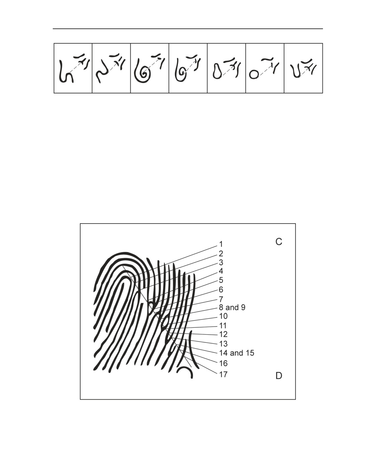
Fingerprinting
Figure 1-10. Placement of the reference line
1-27. Inasmuch as arches and tented arches have no core, a ridge count cannot be done on them because
there is no way to orient the reference line. When these patterns occur, they are assigned a ridge count of
zero. Missing fingers are also assigned a ridge count of zero. When a scar or mutilation between the core
and the delta makes a ridge count impossible, a ridge count of zero is assigned to the finger.
1-28. With the reference line properly oriented on the print, the ridge count is made by counting all of the
ridge lines that cross or touch the reference line, starting with the core as the first ridge counted and ending
with the delta as the last ridge counted. Figure 1-11 below and Figure 1-12, page 1-10, illustrate this
technique on a loop and whorl, respectively.
1-29. In Figure 1-11, lines 8 and 9 and 14 and 15 received a double count because the reference line
crosses at the point where a ridge bifurcates. In keeping with the third rule described in paragraph 1-18,
each of the lines formed by the bifurcation receives a count since they touch the reference line. Lines 5, 6,
10, and 11 of Figure 1-11 and ridge lines 8 and 9 of Figure 1-12 are formed by a ridge line bifurcating on
one side of the reference line and reclosing on the other side of the reference line. However, at the point
where they encounter the reference line there are two distinct ridges, and each receives a count.
Figure 1-11. Ridge count (loop)
30 September 2008
TC 31-20-2
1-9

Chapter 1
Figure 1-12. Ridge count (whorl)
1-30. Because whorl patterns have more than one delta, the FIS dictates which delta is to be used. The
leftmost delta and the core nearest it will be used unless a crease or mutilation on that side would prevent
an accurate count. In such instances, the count is made between the rightmost delta and the core nearest to
it (this fact must be reported in the message transmitting the data). Figure 1-13 shows the placement of the
reference line on typical patterns.
Figure 1-13. Loop pattern, (normal), whorl pattern (normal), and whorl pattern (mutilated)
1-31. Normally, the lowest ridge count would be two—one for the core and one for the delta. However,
rare patterns may be encountered where the core and the delta are the same (Figure 1-14, page 1-11). In
such instances, the ridge count is one.
1-32. A small, two-power magnifier is necessary for ease and accuracy of print interpretation (although, in
emergencies, it is possible to read a perfectly clear print without magnification). The magnifier should be
mounted on some type of stand that allows the analyst to have both hands free to make a ridge count. Field
experience has shown that two individuals counting the ridges on the same print may make an error of two
counts; therefore, an error of plus or minus two is allowable in the ridge count comparison.
1-10
TC 31-20-2
30 September 2008

Fingerprinting
Figure 1-14. Example of rare pattern where core and delta are the same
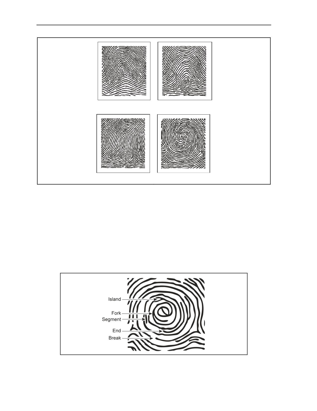
1-33. In the following practical exercise, Figure 1-15, pages 1-11 and 1-12, represents the 10 fingerprint
impressions of an individual. The analyst classifies the pattern and conducts a ridge count on these
impressions. The analyst must remember that there is no allowable error in pattern classification, but an
error of plus or minus two counts is allowable in the ridge count.
Finger 1
Finger 2
Finger 3
Finger 4
Finger 5
Finger 6
Figure 1-15. Fingerprint impressions
30 September 2008
TC 31-20-2
1-11
Chapter 1
Finger 7
Finger 8
Finger 9
Finger 10
Figure 1-15. Fingerprint impressions (continued)
FAULT COUNT
1-34. Faults are peculiar formations occurring on ridges within the pattern area. They tend to interrupt the
continuity of impressions and are the distinguishing features of fingerprints. Faults appear in five forms, as
depicted in Figure 1-16. The five forms are—
z
Islands (ridges that bifurcate and then reclose, forming an island).
z
Forks (single ridges that split [bifurcate] into two ridges).
z
Segments (short fragments of ridges standing alone).
z
Ends (ridges that end abruptly).
z
Breaks (separation or interruption of a ridge on the same plane).
Figure 1-16. Types of faults
1-12
TC 31-20-2
30 September 2008

Fingerprinting
1-35. Faults appear frequently and haphazardly throughout the pattern areas of fingerprints. Their use as
authenticating data for the FIS requires an accurate method for recording the description of the faults and
their location in the pattern area. A template is used in the fault count to provide a means of orienting the
critical faults. The template is a transparent medium upon which reference lines are inscribed. The
reference lines are three parallel lines drawn 2 millimeters (mm) apart and closed at one end by a line
drawn perpendicular to the parallel lines (Figure 1-17). The overall length of the parallel lines only needs
to be as long as is required to reach from the core of an impression to its delta.
Figure 1-17. Template
1-36. The proper position of the template on loop and whorl patterns is with the center line tangent to the
core and through the delta in the same manner that the reference line is placed for the ridge count. The
perpendicular line of the template is placed so that it intersects the core at the point of tangency of the
center line (Figure 1-18).
Figure 1-18. Template positioning on loop, whorl, and loop
1-37. With the template correctly positioned, the only faults to be considered for the fault count are those
which appear within the 4-mm area bounded by the right and left parallel lines, below the cross line
intersecting the core, and above the delta. The Soldier does not count the faults that occur—
z
Outside the limits.
z
On the core.
z
On the delta.
Note: When a fault is partly inside and partly outside the limits of the template, its description
will be limited to only that part of the fault which is inside the limits of the template.
1-38. The numbering of faults is governed by the ridge count. Faults appearing on ridges that cross or
touch the center line of the template receive the same number as the ridge on which they occur. When more
30 September 2008
TC 31-20-2
1-13
Chapter 1
than one fault appears on the same ridge line, every fault on that ridge receives the same number. Faults
appearing on ridge lines that do not cross or touch the center line of the template receive the number of the
ridge immediately above them.
1-39. The two columns created by the three parallel lines of the template provide a means of locating the
faults as well as adding direction to their other characteristics. Looking at the template with the core
oriented away from the viewer, the columns are described as the left-hand column and the right-hand
column. The fault descriptions are composed of the following two or three letters:
z
The first letter identifies the type of fault.
z
The second letter states the location of the fault (in the left column, in the right column, or on
the center line).
z
The third letter (when there is a third letter) gives the direction in which a fork opens, the
direction in which an end points, or in which column the greater parts of a segment, island, or
break appear when they are on the center line but slightly off center.
1-40. When more than one fault appears on a ridge line or has the same number, those faults appearing in
the left-hand column of the template are reported first, those in the right-hand column second, and those
that touch the center line last. Each ridge line will be completely fault-counted before moving on to the
next ridge line.
1-41. When two or more faults have the same number and location, the direction or movement of the fault
is used to determine the sequence of reporting. In these circumstances, faults pointing to the left are
reported first, those pointing to the right are reported second, and those with no direction are reported last.
1-42. To clarify these reporting procedures, all faults—regardless of type—with the same number are
reported in the following sequence:
z
Those in the left column pointing left (LL).
z
Those in the left column pointing right (LR).
z
Those in the left column with no direction (segments, breaks, and islands) (L).
z
Those in the right column pointing left (RL).
z
Those in the right column pointing right (RR).
z
Those in the right column with no direction (R).
z
Those on the center line pointing left (forks or ends) or with the major portion of the fault in the
left-hand column (segments, breaks, and islands) (CL).
z
Those on the center line pointing right or with the major portion of the fault in the right-hand
column (CR).
z
Those directly on the center line with no direction or with no part of the fault offset by a
majority to either side of the center line (C).
1-43. The core and the delta never have a reportable fault. No fault will ever have the same number as the
delta. A fault may have the number one if it appears between the core and ridge line number two.
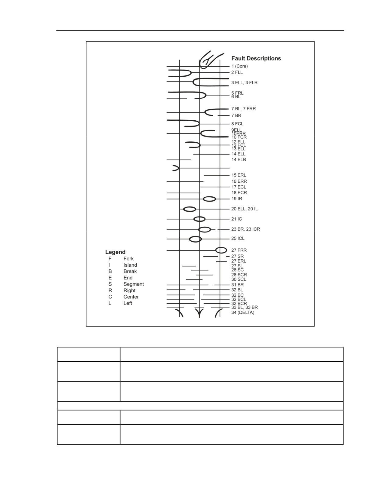
1-44. Figure 1-19, page 1-15, is a line drawing of the critical part of a pattern area on which a correctly
placed template has been superimposed. The drawing illustrates many of the variations of faults that may
appear in fingerprint impressions and the method used for numbering and describing the faults. The
abbreviations used for the fault descriptions are explained in the legend to the left of the illustration. All of
the faults illustrated in Figure 1-19 are described in Figure 1-20, pages 1-15 through 1-17.
1-14
TC 31-20-2
30 September 2008
Fingerprinting
Figure 1-19. Sample fault count
2FLL
Indicates a fork on the second ridge line, in the left column of the template, opening to the left.
(Fork Left-Left)
3ELL
Indicates an end on the third ridge line, in the left column of the template, pointing to the left.
(End Left-Left)
Because this fault appears on a ridge line that does not cross or touch the center line, it
receives the number of the ridge line immediately above it.
3FLR
Indicates a fork on the third ridge line, in the right column, opening to the right. Note that double
(Fork Left-Right)
line faults, such as forks and islands, are given the number of the first of its ridges that cross or
touch the center line.
Ridge line 4 contains no faults and is not reported.
5FRL
Indicates a fork on the fifth ridge line, in the right column, opening to the left.
(Fork Right-Left)
6BL
Indicates a break on the sixth ridge line in the left column. A break does not have direction
(Break Left)
unless it is located on the center line. Although this ridge is part of the fork on ridge line five, it
also touches the center line and therefore is reported separately.
Figure 1-20. Detailed fault count description
30 September 2008
TC 31-20-2
1-15
Chapter 1
7BL
Indicates a break on the seventh ridge line entirely in the left column.
(Break Left)
7FRR
Indicates a fork in the right column opening to the right.
(Fork Right-Right)
7BR
Indicates a break in the right column. It receives a count of 7 because the ridge line it appears
(Break Right)
on does not cross or touch the centerline, and it therefore receives the number of the line
above.
8FCL
Like all double faults, it receives the number of the first line that crosses or touches the center
(Fork Center-Left)
line.
9ELL
Indicates an end in the left column pointing to the left. This fault appears on the lower tine of the
(End Left-Left)
fork and so that count is advanced by one.
1OERR
Indicates an end in the right column pointing to the right. It appears on the upper tine of the fork.
(End Right-Right)
1OFCR
Indicates a fork originating directly on the center line opening to the right. This fault is similar to
(Fork Center-Right)
8FCL but opens in the opposite direction.
Ridge line 11 is the bottom tine of the fork and has no faults; therefore it is not included in the fault count.
12ELL
Indicates an end on the upper tine of the fork in the left column pointing to the left.
(End Left-Left)
12FCL
Indicates a fork originating on the center line opening to the left. It is the same as fault 8FCL
(Fork Center-Left)
(paragraph 9i).
13ELL
Indicates an end in the left column pointing to the left. It is the same as 12ELL (paragraph 9m)
(End Left-Left)
except it is on the bottom tine of the fork.
14ELL
Indicates an end in the left column pointing to the left.
(End Left-Left)
14ELR
Indicates an end in the left column pointing to the right. The ridge line does not cross or touch
(End Left-Right)
the center line, and therefore it receives the number of the line above.
The fork appearing on ridge line 15 is outside of the limits of the template; therefore it is not included in the fault count.
15ERL
Indicates an end in the right column pointing to the left. The ridge line does not cross or touch
(End Right-Left)
the center line and therefore receives the number of the line above.
16ERR
Indicates an end in the right column pointing to the right.
(End Right-Right)
17ECL
Indicates an end directly on the center line pointing to the left.
(End Center-Left)
18ECR
Indicates an end directly on the center line pointing to the right.
(End Center-Right)
19IR
Indicates an island completely within the limits of the right column. Notice that no direction is
(Island Right)
reported for this fault since it does not touch the center line.
20ELL
Indicates an end in the left column pointing to the left. It is the continuation of the ridge that
(End Left-Left)
forms the island.
20IL
Indicates an island completely within the left column. It has no direction since it does not touch
(Island Left)
the reference line.
21IC
Indicates an island directly centered on the reference line. Like all double line faults, it receives
(Island Center)
the count of the first line that crosses or touches the center line.
Ridge line 22 is the bottom line of the island and has no faults; therefore it is not included in the fault count.
23BR
Indicates a break in the right column. The fault does not have a direction since it is not on the
(Break Right)
reference line. The line the fault appears on does not cross or touch the center line so it
receives the count of the ridge line above. This fault could have been described as ERL and
ELL, but this description would have entailed additional letters and longer transmission time.
23ICR
Indicates an island on the center line with the majority of the fault in the right column. Like all
(Island Center-Right)
double line faults, it receives the count of the first line to touch the center line.
Ridge line 24 (the bottom line of the fault) has no faults and therefore is not included in the fault count.
25ICL
Is the same as 23ICR except the majority of the fault is in the left column.
(Island Center-Left)
Figure 1-20. Detailed fault count description (continued)
1-16
TC 31-20-2
30 September 2008
Fingerprinting
27FRR
Indicates a fork in the right column opening to the right. Although the complete fault is an island,
(Fork Right-Right)
the part within the right limit of the template becomes a fork.
27SR
Indicates a segment in the right column. Since it is not on the center line, it has no direction and
(Segment Right)
receives the count of the ridge line above it that touches the reference line.
27ERL
Indicates an end in the right column pointing to the left. Although this complete fault is a
(End Right-Left)
segment, the right limit of the template cuts through it and the part within the limit of the
template is an end. It has no count of its own and therefore will receive the count of the last
ridge line above it that crosses or touches the reference line.
27SL
Indicates a segment in the left column. Since it does not cross or touch the reference line, it has
(Segment Left)
no direction, and it receives the number of the line above. This fault could be described as ELL
and ELR, but this description would have entailed additional letters and longer transmission
time.
28SC
Indicates a segment directly on the center line. It has no direction since it does not have a
(Segment Center)
majority in either column of the template.
28SCR
Indicates a segment on the center line with the majority of the fault in the right column.
(Segment Center-Right)
30SCL
Indicates a segment on the center line with a majority of the fault in the left column.
(Segment Center-Left)
31BR
Indicates a break entirely in the right column. It does not have any direction since it does not
(Break Right)
touch the center line.
32BL
Indicates a break entirely in the left column. It does not have any direction since it does not
(Break Left)
touch the center line.
32BC
Indicates a break that exactly straddles the center line.
(Break Center)
32BCL
Indicates a break straddling the center line with the majority of the fault in the left column.
(Break Center-Left)
32BCR
Indicates a break straddling the center line with the majority of the fault in the right column.
(Break Center-Right)
Because none of these breaks are on ridge lines that cross or touch the center line, they all receive the count of the ridge
line above them that does touch the reference line.
33BL
Indicates a break entirely in the left column.
(Break Left)
33BR
Indicates a break entirely in the right column.
(Break Right)
Neither of these faults has a direction because they are not on the reference line. These two faults could be described in
other ways, but this method uses the fewest letters and would result in the shortest transmission time.
34 (DELTA)
The fault count ends at the beginning of the delta. The delta is discussed in other paragraphs.
Figure 1-20. Detailed fault count description (continued)
1-45. There will be rare cases when a fault count is required on an individual whose 10 fingers do not
contain 2 readable loops or whorls. In such instances, it will be necessary to use arches for the fault count.
Because an arch does not have a core, the lockpoint method is used to provide a means of orienting the
template (Figure 1-21, page 1-18). A step-by-step procedure for employing the lockpoint method for fault
count on arches is as follows:
z
Place the template over the print so that the center line runs approximately through the center of
the impression from the tip to the line of cleavage.
z
Scan the print and select an easily identifiable fault near the bottom of the print above the line of
cleavage and as close to the center line as possible.
z
Scan the print again and select an easily identifiable fault near the top of the impression as near
the center line as possible.
z
Readjust the template so that the center line passes through or touches the selected faults. This
procedure locks the template into position so that faults can be described. In the lockpoint
method, the center line of the template touches ends, crosses the bifurcation of forks, and passes
through the center of segments, breaks, and islands.
30 September 2008
TC 31-20-2
1-17

Chapter 1
z
Identify the bottom lockpoint by counting the ridges that cross or touch the center line starting at
the line of cleavage and proceeding upward through the impression. Give the fault that ridge
number and identify it both as it appears within the template and as a lockpoint. For example, in
Figure 1-21, 5ECLLP is an end center-left, on the fifth ridge line up from the line of cleavage,
and is the lockpoint.
z
Continue a normal fault count, counting upwards to the top lockpoint, which is the last fault
described. The rules of fault count for loops and whorls apply, with the exception that the count
is upwards in the lockpoint method.
z
Identify the top lockpoint in the same manner as the bottom lockpoint. In Figure 1-21, 33ICLP
is an island center on the 33rd ridge up from the line of cleavage and the lockpoint.
Note: All double-line faults receive the count of their lower ridge. This method is in keeping
with the rule that all double-line faults receive the count of the first line that touches the
reference line. The faults appearing on ridge lines that do not cross or touch the center line still
receive the count of the line above. In the lockpoint method, this count will always be the larger
number, whereas in the fault count of loops and whorls, this count will be the lower number.
Figure 1-21. Lockpoint
1-18
TC 31-20-2
30 September 2008
Chapter 2
Taking a Set of Fingerprints
OVERVIEW
2-1. A set of fingerprints should cover the area from nail bed to nail bed and from the tip of the finger to
below the first joint. Prints must be clear enough to be classified and numbered. The equipment needed for
taking fingerprint impressions is simple and inexpensive. It consists of a marking substance (ink or dye)
and a smooth surface. Standard items of equipment may not be available, and SF Soldiers may have to
improvise from locally available material.
NECESSARY MATERIALS
2-2. The substance used to obtain fingerprint impressions must spread evenly on the fingers and allow for
the transfer to the interpreting surface. The standard item is printer’s ink, which is a heavy, black paste.
Other substances, when applied with care, will also produce acceptable impressions. These substances
include the following:
z
Cheap lipstick. Cheaper lipstick works better because the oils in cheaper brands mix better with
the natural oils of the fingers.
z
Stamp pad inks with stamp pads. These inks can be used; however, stamp pad ink is very light
or thin and takes a long time to dry. If possible, a pad with a silk cloth should be used. The silk
cloth is not as likely to cause clotting as cotton cloth, thus allowing a more even flow of ink.
z
Soot. By holding a piece of glass at an angle over an open flame, a thin film of soot forms on the
glass. The finger may then be rolled in the soot and then on paper. This procedure will produce a
usable impression.
z
Charred wood. Charred wood may be pulverized and thinned with a liquid to make a usable ink.
To obtain the best results, the liquid that is added should have a slightly oily base.
z
Berry juice. The juice of most berries can be used; however, the impressions obtained are
normally light.
z
Shoe polish. Polish that has a lanolin base—not a wax base—should be used. Any substance
with a wax base tends to clot, causing smudged or smeared impressions.
2-3. A smooth surface should be used to get the fingerprint impression. The surface may be of any
material suitable to accept the inked impression. Suitable surfaces include the following:
z
Index cards (3 by 5 inches or 5 by 8 inches). Because of their heavy weight, both sides can be
used. These cards may also be used for a permanent fingerprint file.
z
Magazines. A magazine, especially one with a slick surface, has an excellent surface for
temporary prints. Although not all of the magazine can be used, several pages will normally
have large borders that can be used to take a few individual prints.
z
Newspaper. The paper used for newspapers holds ink; therefore, it is not the best type of surface
to use. By soaking in water, newspapers can be bleached out and then dried in the sun. This
procedure will produce a large amount of usable paper.
z
Glass. Flat pieces of glass or plastic may be used; however, their hard surfaces make them
difficult to work with. Care must be taken to avoid smearing the impressions.
z
Wood. A flat piece of wood sanded or painted smooth makes an excellent surface. It has the
added advantage of being reusable simply by being cleaned, sanded, or repainted.
30 September 2008
TC 31-20-2
2-1

Chapter 2
2-4. Figure 2-1 is an example of a typical commercially available fingerprint identification kit. The
minimum contents of this kit should include the following:
z
Carrying case.
z
Index cards (5 by 8 inches).
z
Fingerprint ink.
z
Roller (used with fingerprint ink).
z
Inking plate (used with fingerprint ink).
z
Card holder.
z
Magnifier.
z
Reading glass (used as magnifier).
z
Template.
z
Curved spatula (used for deformed fingers).
Figure 2-1. Typical commercially available fingerprint identification kit
2-5. There is a wide variety of equipment available for taking fingerprints. Figure 2-2, page 2-3, is an
example of a commercially available compact fingerprint identification station. Figure 2-3, page 2-3, is an
example of a commercially available inkless fingerprint kit. Figure 2-4, pages 2-3 and 2-4, shows examples
of field-expedient inking materials, to include shoe polish, camouflage stick, lipstick, stamp pad, and
camouflage compact. Figure 2-5, page 2-4, is an example of a field-expedient fingerprint card with
handwritten information blocks. Figure 2-6, page 2-5, shows commercially available magnifiers. Figure 2-7,
page 2-6, shows examples of biometric AFIS equipment available through the BFC representative or the
operational group headquarters (HQ).
2-2
TC 31-20-2
30 September 2008

Taking a Set of Fingerprints
Figure 2-2. Commercially available compact fingerprint identification station
Figure 2-3. Commercially available inkless fingerprint kit
Figure 2-4. Examples of field-expedient inking material
30 September 2008
TC 31-20-2
2-3

Chapter 2
Figure 2-4. Examples of field-expedient inking material (continued)
Figure 2-5. Example of field-expedient fingerprint card
2-4
TC 31-20-2
30 September 2008

Taking a Set of Fingerprints
Figure 2-6. Examples of commercially available magnifiers
30 September 2008
TC 31-20-2
2-5

Chapter 2
Figure 2-7. Examples of biometric equipment
TECHNIQUES
2-6. To get the best possible results, the Soldier should apply a number of techniques. These techniques
include the following:
z
Ensure that all the necessary equipment is available, clean, and in working order.
z
Select a location that provides a degree of privacy and a sufficient source of light.
z
Organize the printing area, arrange the working surface, and ink the printing plate.
2-7. The working surface should be arranged so that the subject being fingerprinted stands in front of and
at forearm’s length from the surface. The height of the working surface should be even with the subject’s
elbow when his arm is hanging naturally to his side (when the arm is bent to a right angle, the forearm will
be even with the surface). The card and inking plate should be mounted at the edge of the surface so that
2-6
TC 31-20-2
30 September 2008
Taking a Set of Fingerprints
the subject’s fingers will not interfere with the manipulation of the other fingers during the printing
process.
2-8. To ink the printing plate properly, the Soldier should place two or three small daubs (about the size
of a match head) of printer’s ink on the plate and thoroughly roll until a thin, even film covers the entire
surface. The inked plate should be checked to ensure the film is neither too heavy (smudged prints) nor too
light (undefined prints).
2-9. Prior to inking the fingertips, the Soldier should ensure that the subject’s fingers are clean. Lint, dust,
dirt, or gummed ink in the pattern area can cause imperfect impressions, void identifying characteristics, or
print false markings. Alcohol, gasoline, or soap and water are suitable for cleaning. If the skin is rough or
callused and difficult to print, the hands should be washed and, if necessary, soaked in warm water.
Soaking softens the skin and brings out the ridges. After soaking, the hands should be dried thoroughly—
moisture on the hands will blur the prints.
2-10. For proper and accurate analysis, the Soldier must ensure that all critical areas of the fingerprints are
imprinted. The fingers must be inked properly and rolled (rather than pressed) to obtain the impressions. In
taking rolled impressions, the bulb of the finger is placed at right angles to the surface and then turned or
rolled until the bulb faces in the opposite direction. To obtain uniform impressions, the Soldier may take
advantage of the natural finger movement—the fingers are turned away from the awkward to the easy
position. Such movement relieves strain and leaves the fingers relaxed so that they may be lifted easily
from the surface without slipping. Slipping causes the prints to smudge and blur.
2-11. If an individual holds his arms in front of him with the backs of his hands touching each other, his
hands feel strained and awkward. If he turns his hands over so they are palm to palm, they are in a
comfortable position. When taking fingerprints, the Soldier should roll the fingers by starting in the
awkward position (Figure 2-8) and ending with them in the comfortable position (that is, rolled away from
the center of the subject’s body).
Figure 2-8. Completing the roll of the finger from “awkward-to-comfortable” position
2-12. If an individual holds both hands in front of him with palms up and thumbs extended, the inside
edges of the thumbs will be down and the person will feel strain. If he holds both hands in front of him
with the palms down, the outside edges of the thumbs will be down and he will be comfortable. Therefore,
in rolling the thumbs, the Soldier should roll the thumb toward the center of the subject’s body (Figure 2-9,
page 2-8).
2-13. When taking fingerprints, each finger must be inked evenly from the tip to below the first joint and
from nail edge to nail edge. Each finger should be inked and printed separately, not all at once. In inking
and taking rolled impressions, the amount of pressure used is important; proper pressure can best be
30 September 2008
TC 31-20-2
2-7
Chapter 2
determined through experience and observation. It is quite important, however, that the subject relaxes,
refrain from helping, and not exert any pressure that will prevent the Soldier from gauging the amount of
pressure needed. One way to get the subject to relax his hand is to have him look at the opposite wall
instead of his hands. It also helps if the Soldier can stand between the subject and the working surface.
Figure 2-9. Completing the roll of the right thumb
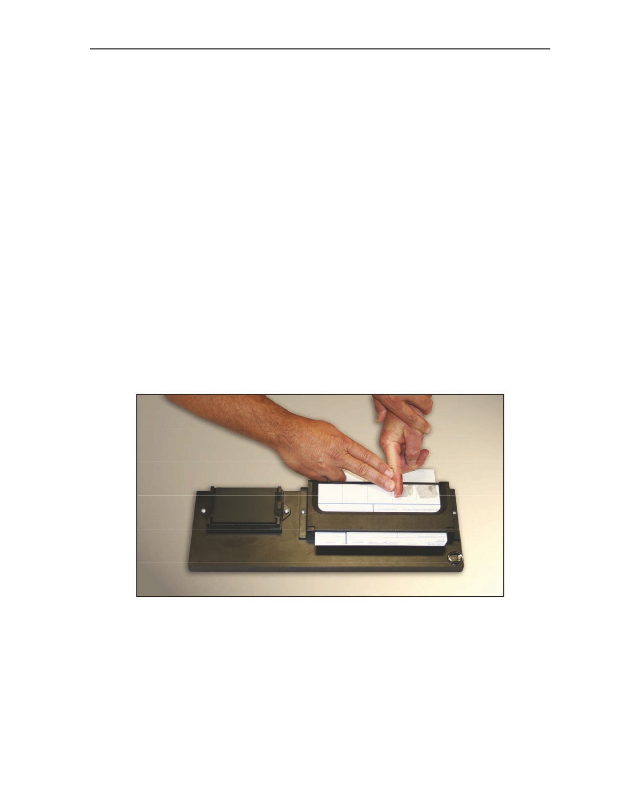
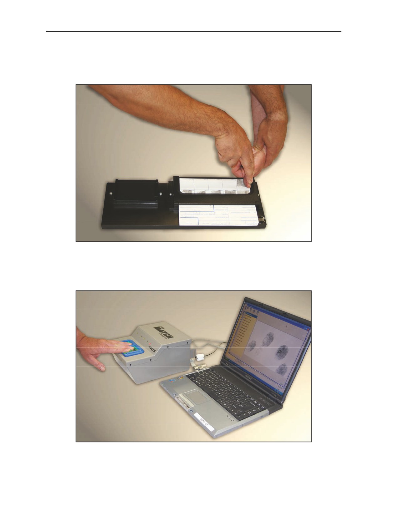
2-14. Figure 2-10 shows fingerprints taken with biometric AFIS equipment. Figure 2-11, page 2-9, shows
the thumbprint being taken using this equipment. When using biometric equipment, it is not necessary to
roll the finger to obtain a print (Figure 2-12, page 2-9).
Figure 2-10. Fingerprints taken with biometric equipment
2-8
TC 31-20-2
30 September 2008

Taking a Set of Fingerprints
Figure 2-11. Thumbprint taken with biometric equipment
Figure 2-12. Fingerprint taken with biometric equipment
2-15. The procedure for inking the fingers is the same as that described for taking the prints. A finger
should not be rolled back and forth on the inking plate to get enough ink. If insufficient ink is transferred
the first time, the finger should be re-inked on another portion of the inking plate. A finger should never be
inked at a place on the inking plate where a finger was previously inked. This practice will result in uneven
inking, causing missed or voided characteristics.
2-16. A slightly different procedure is used when applying lipstick to the fingers to take a set of
impressions. The lipstick should be applied directly to the fingers. To coat the fingers uniformly, lipstick
should be applied in one sweeping motion beginning below the first joint and ending at the tip of the
30 September 2008
TC 31-20-2
2-9

Chapter 2
finger. Since more than one motion is normally needed to cover a fingerprint, a slight overlap should be
allowed in each subsequent application. Soldiers should avoid using back-and-forth motions, as this type of
motion will fill in the furrows between the ridges, causing smudged and blurred impressions.
STANDARD NUMBERING OF THE FINGERS
2-17. The standard method of numbering the fingers in the FIS permits the data to be transmitted in a
message without numbering the data for each finger. This procedure only requires that the data be
transmitted in proper order—the data for the first finger appearing first in the message, followed by the
data for the second finger, and so on. This procedure also ensures that individuals at various locations will
derive the same information from received messages dealing with fingerprint identification.
2-18. The FIS is devised for 10 fingers. In the FIS, the fingers are always numbered, palms down, starting
with the little finger of the left hand as finger number 1 and proceeding across the back of the hands. Each
finger is numbered in order until the little finger of the right hand is numbered (Figure 2-13). Therefore, in
the standard method of numbering, the fingers of the left hand will always be numbered 1 through 5 and
the fingers of the right hand will always be numbered 6 through 10.
2-19. When a finger or fingers are missing, the numbers stay as if all fingers were present. For example, if
the ring finger of the left hand is missing, the little finger on the left hand is still number 1, the missing
finger is number 2, the middle finger on the left hand is still number 3, and so forth (Figure 2-14, page 2-11).
The same would be true if the left hand were missing. The missing fingers of the left hand would still be
numbers 1 through 5, and right hand fingers would still be numbers 6 through 10 beginning with the thumb
and ending with the little finger. The missing fingers would be reported in the fingerprint message.
Figure 2-13. Standard numbering of the fingers
2-20. An individual with 11 or more fingers presents a special situation. The first consideration for any
additional finger is that it must have an identifiable fingerprint. It will then be given the number in the
sequence where it appears, using the rule counting from left to right, palms down (Figure 2-15, page 2-11).
If the additional finger does not have an identifiable fingerprint, it is not included in the finger count. All
additional fingers, regardless of the presence of an identifiable fingerprint, should be reported in the FIS
message.
2-10
TC 31-20-2
30 September 2008
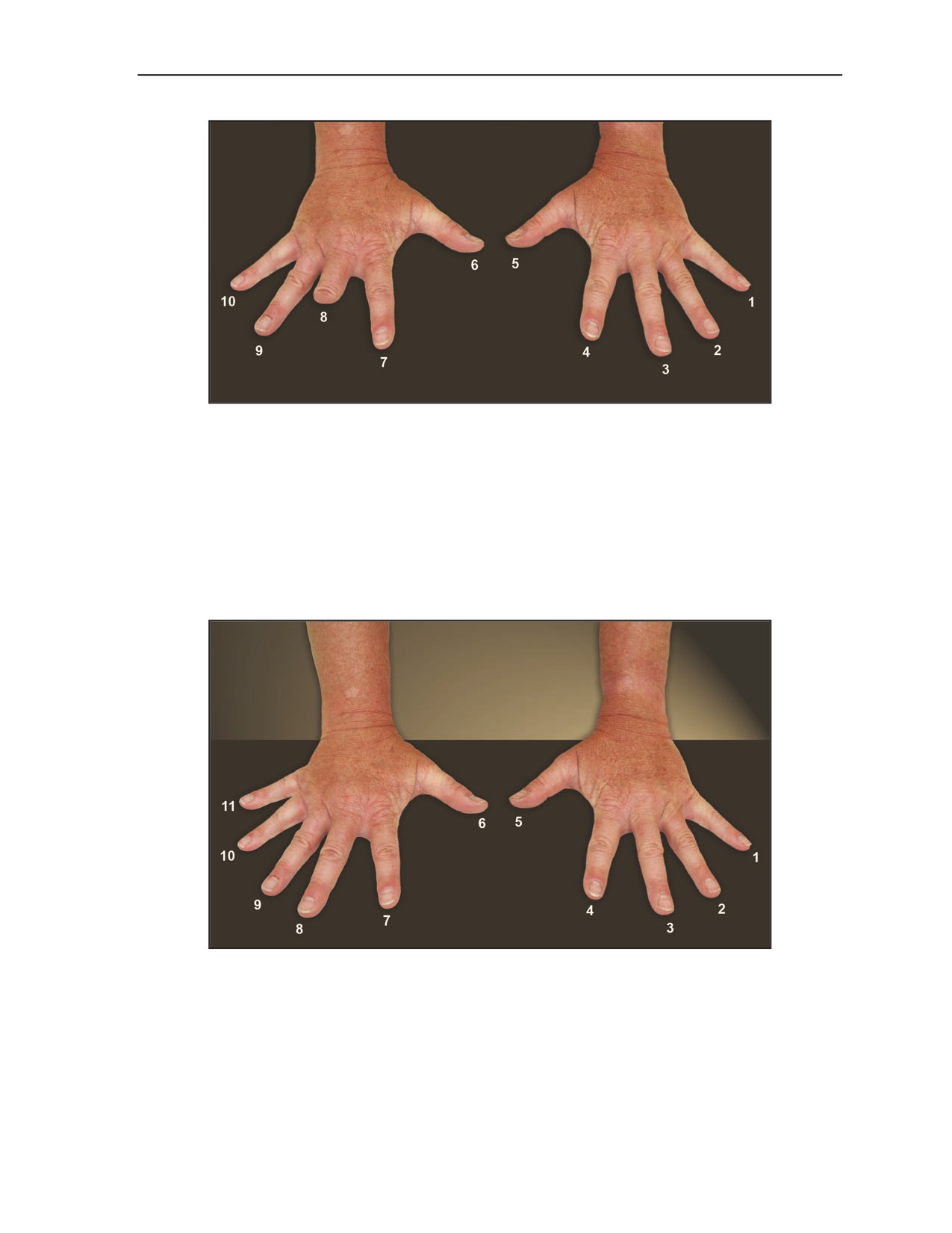
Taking a Set of Fingerprints
Figure 2-14. Finger numbering when finger is missing
2-21. Cuts, scratches, blisters, and wounds fall in the category of temporary disabilities. Given time, these
problems will cure themselves. If the time is not readily available, the Soldier must be patient and use
extreme care to obtain the best possible impression in spite of the disabilities.
2-22. Some of the physical disabilities encountered in taking fingerprint impressions are permanent. The
system provides for some of these permanent disabilities, such as missing or extra fingers. Other permanent
disabilities, such as deformed or mutilated fingers, may require the use of special equipment (such as the
curved spatula) or techniques. In addition, Soldiers must use extra care to obtain the best possible
impressions.
Figure 2-15. Finger numbering when an extra digit is present
2-23. The final category—general—deals primarily with errors made in the interpretation of the
impressions and the transmission of fingerprint data. Misinterpretation of impressions, misuse of the
brevity code, incomplete data, or transmission of data in the wrong sequence are examples of these errors.
Attention to detail will eliminate most of these problems. Figure 2-16, pages 2-12 and 2-13, shows a
sample of Standard Form (SF) 87A (Fingerprint Chart), also known as a FIS record card.
30 September 2008
TC 31-20-2
2-11

Chapter 2
Figure 2-16. Sample of SF 87A (Fingerprint Chart)
2-12
TC 31-20-2
30 September 2008
Taking a Set of Fingerprints
Figure 2-16. Sample of SF 87A (Fingerprint Chart) (continued)
CONVERTING FINGERPRINT DATA FOR RADIO TRANSMISSION
BY USING THE BREVITY CODE
2-25. The identification of an individual is either confirmed or refuted by the comparison of a set of
impressions (fingerprints). Because the means of communication between elements may be by radio,
Soldiers must be familiar with converting fingerprint information into a format for radio transmission and
message formats.
2-26. To convert the data interpreted from a fingerprint impression into a form adaptable to radio
transmission, a brevity code is used. As the name implies, this code is used only for brevity and in no way
provides security for transmitted data. Security is provided by encrypting the brevity coded messages. This
brevity code will be used only for the fingerprint data and will not be used for the personal data that form a
30 September 2008
TC 31-20-2
2-13
Chapter 2
part of the messages. When converting fingerprint data to the brevity code, they must be transmitted in the
following order:
z
Pattern.
z
Ridge count.
z
Additional data.
2-27. The first part of the brevity code is the numerical code (Figure 2-17) used for ridge counts and the
numbers assigned in fault count identification. All numbers reported in the messages have two digits.
Therefore, single digit numbers will have a zero placed in front of them before encoding. For example,
using the data in Figure 2-17, a ridge count of 9 would be 09 and encoded JI. Because arches, tented
arches, missing fingers, and mutilated fingers (on which no ridge count is possible) are assigned a ridge
count of zero, their ridge count would be encoded as JJ.
1
2
3
4
5
6
7
8
9
0
A
B
C
D
E
F
G
H
I
J
Figure 2-17. Numerical brevity code
2-28. The second part of the brevity code is the pattern classification code (Figure 2-18). In this code, the
major pattern classifications—arches, loops, and whorls—and the subdivisions of arches and loops fall in
alphabetical order. All of the codes are composed of repeated double letters.
Arch
Tented Arch
Finger Loop
Thumb Loop
Whorl
KK
LL
MM
NN
OO
Figure 2-18. Pattern classification brevity code
2-29. The identification of an individual is either confirmed or refuted by the comparison of a set of
impressions (fingerprints). Because the means of communication between elements may be by radio,
Soldiers must be familiar with converting fingerprint information into a format for radio transmission and
message formats.
2-30. To convert the data interpreted from a fingerprint impression into a form adaptable to radio
transmission, a brevity code is used. As the name implies, this code is used only for brevity and in no way
provides security for transmitted data. Security is provided by encrypting the brevity coded messages. This
brevity code will be used only for the fingerprint data and will not be used for the personal data that form a
part of the messages. When converting fingerprint data to the brevity code, they must be transmitted in the
following order:
2-31. In the third part of the brevity code—the fault count (Figure 2-19, page 2-15)—double letters are
used. The first letter of the code indicates the type of fault and the second letter completes the description
(location and direction, if applicable). The fault description code letters follow an alphabetical sequence in
keeping with the reporting order of faults.
2-32. The final part of the brevity code is the miscellaneous code (Figure 2-20, page 2-15). This part of the
code is used for the oddities that occur in fingerprint impressions and allows the analyst to further clarify
questionable data.
2-33. Any time a finger is missing, it is encoded with the double letter PP. Because all missing fingers
have a ridge count of zero assigned, they will have a complete code of PPJJ. If a complete hand is missing,
every finger on that hand is so reported.
2-14
TC 31-20-2
30 September 2008
Taking a Set of Fingerprints
Fork
End
Island
Segment
Break
Left Left
Left Left
Left
Left
Left
RR
SR
TR
UR
VR
Left Right
Left Right
Left
Right
Right
RS
SS
TS
US
VS
Right Left
Right Left
Center Left
Center Left
Center Left
RT
ST
TT
UT
VT
Right Right
Right Right
Center Right
Center Right
Center Right
RU
SU
TU
UU
VU
Center Left
Center Left
Center
Center
Center VV
RV
SV
TV
UV
VV
Center Right
Center Right
RW
SW
Figure 2-19. Fault count brevity code
Data
Code
Missing Finger
PP
Mutilated Finger
QQ
Question
YY
Right Delta
WS
Lockpoint
WT
Separator
ZZ
Begin/End Fingerprint Data
ZZZZ
Figure 2-20. Miscellaneous brevity code
2-34. The double letter QQ indicates a mutilated finger. It must be used when the mutilation affects the
pattern classification and/or ridge count and may be used as a further means of identification even though
the pattern classification and/or ridge count is not affected. When the mutilation makes an accurate pattern
classification impossible, the code QQJJ is entered for the finger. If the mutilation makes an accurate ridge
count impossible, but does not affect the pattern classification, the code will follow immediately after the JJ
indicating a ridge count of zero.
2-35. If the mutilation causes some confusion in respect to the pattern classification but does not
completely make classification impossible, the code is placed between the two classifications. For example,
an impression believed to be a thumb loop with a ridge count of 04 which—because of a mutilation—could
be a tented arch would be encoded NNQQLLJD.
2-36. If the mutilation appears on a whorl pattern, but it only causes a difference in using the right delta
instead of the left delta, it would be encoded OOAFWSQQ (a whorl, a ridge count of 16, using the right
delta because of a mutilation). When a mutilation does not affect either the pattern classification or ridge
count, it may be indicated at the end of the encoded impression as a means of further identification.
2-37. The double letter code YY allows the analyst to question any of the information he is not positive
about in his interpretation. If, during pattern classification, the analyst believes an impression is a finger
30 September 2008
TC 31-20-2
2-15
Chapter 2
loop with a ridge count of two, but he is not quite sure that it is not a tented arch, he would encode this
pattern MMJBLLJJ.
2-38. Although it is not advisable, an analyst can question the ridge count in the same manner as he
questions a pattern classification. Therefore, a thumb loop with a ridge count of 14 or 15 would be encoded
NNADYYAE. Normally, ridge counts are not questioned because of the allowable error of plus or minus
two counts. The question code can be used in a multitude of other ways, as long as both analysts
understand how it is being used and derive the same information from it.
2-39. The code WS indicates the use of the right delta in obtaining the ridge count on a whorl type pattern.
This indicator follows the ridge count at all times and may be used in conjunction with other codes. The
code WT identifies the lockpoints used to orient the template when making a fault count on either an arch
or tented arch pattern.
2-40. The repeated letter code ZZ is used in the additional data message to separate the fault count and
repeated fault count on the same finger. It is not used to separate the data on the two fingers being fault
counted.
2-41. The four-letter repeated code ZZZZ is used to indicate the beginning and end of the fingerprint data
contained in the messages. The indicator at the beginning of the fingerprint data also will separate the
fingerprint data from the personal data of the individual. The ZZZZ at the end of the fingerprint data will
normally indicate the end of the message.
2-42. The brevity code is used to standardize the order in which information is transmitted and can be used
any time face-to-face communication is not possible. The brevity codes can be used when communicating
by written text, telephone, radio (frequency modulation, amplitude modulation, or very high frequency),
satellite communications, or any other form of communications. When transmitting messages that deal with
the FIS, from lower (tactical element) to higher HQ element requesting assistance in positive identification
of an individual, the message format is codeword PASTE. This message format is found in the command
and control section of the Standard Audiovisual Services Supplement (SAV SER SUP), entitled “E&R
Fingerprint Fault Count Data Report.” These messages follow a prescribed format and sequence for ease of
use and clarity. This report indicates to the higher HQ that the subordinate unit has someone in its AO that
it wishes to identify. The format is shown in Figure 2-21, pages 2-16 and 2-17.
2-43. The higher HQ replies to the request for fingerprint data using the PRINT message format also found
in the command and control section of the SAV SER SUP, entitled “E&R Authentication Data Report.”
The higher HQ will convert the plain text pattern and ridge count of all fingers using the brevity code. The
subordinate unit uses the brevity code to decode the received fingerprint data into lain text equivalents. The
format for this message is depicted in Figure 2-22, page 2-17. In unconventional assisted recovery and
nonconventional assisted recovery operations, the lower tactical element can send the higher HQ or
receiving station the information from the PRINT and PASTE report formats in an effort to verify the
identification of an individual through the AFIS assets.
Proword/Codeword PRINT.
This element identifies the type of message and will be found in the current SAV SER SUP.
1. First name, middle name, family name, date of birth (DOB) (repeat [RPT] the first name,
middle name, family name, and DOB), nationality, and branch of service.
The subject’s name is transmitted in the following order: first name, middle name, and last name. If the subject
has only a single letter (initial) in any element of his name, it will be repeated three times. If the individual is a
first, second, third, junior, or senior, this fact will be spelled out in the sequence used by the individual (for
example, Samuel M. Jones III would be SAMUEL MMM JONES THIRD).
The date is presented as day, month, and year. The individual’s year of birth is spelled out in two digits. If the
individual’s day of birth has only a single digit, a zero is placed in front of it. The month of birth may be
abbreviated using the standard three-letter abbreviations (for example, a DOB of 5 February 1935 would be
reported as ZERO FIVE FEB THREE FIVE).
Figure 2-21. Brevity code format PRINT
2-16
TC 31-20-2
30 September 2008
Taking a Set of Fingerprints
RPT.
Full Name.
Exactly as the first time.
DOB.
Exactly as the first time.
Nationality.
The individual’s nationality is either spelled out or abbreviated, using standard abbreviations. If the standard
abbreviation consists of initials, they will be repeated three times (for example, a U.S. citizen would be
reported as UUU SSS).
Service.
If the individual is in the armed forces, branch of service will be entered. If initials are used to indicate the
branch of service, they will be repeated three times. If the individual’s nationality is different from the country of
his branch of service, the branch of service will be preceded by the country designation (for example, a
German national serving in the USAF would be reported as GERMAN [nationality] UUU SSS AAA FFF
[country and branch of service]). For a civilian, this element will be deleted.
2. Evasion and Recovery Fingerprint Codes.
3. Authenticator question: answer; RPT answer. (This information would only be provided from
higher to lower because it would be extracted from the Personnel Recovery Mission Software/
Isolated Personnel Report form.)
4. Height in inches or centimeters, color of eyes, color of hair.
5. Authenticator number; RPT authenticator number.
6. Additional information (to include disposition instructions).
Any additional information that would aid the higher HQ in the identification procedures may be included in this
part of the message. Any circumstance involving extra fingers must be included in this part of the message. If
identification is confirmed, the higher HQ may instruct the UART to move the individual to an extraction/
recovery location for pickup.
Figure 2-21. Brevity code format PRINT (continued)
Proword/Codeword PASTE.
This element identifies the type of message and will be found in the current SAV SER SUP.
1. Full Name.
The subject’s name is transmitted in the following order: first name, middle name, and last name. If the subject
has only a single letter (initial) in any element of his name, it will be repeated three times. If the individual is a
first, second, third, junior, or senior, this fact will be spelled out in the sequence used by the individual (for
example, Samuel M. Jones III would be SAMUEL MMM JONES THIRD).
2. Number of the fingers from which the data is gathered. (Normally, only two fingers are used
for brevity purposes.)
3. Converted Fault Count Data on the First Finger.
4. Converted Fault Count Data on the Second Finger.
5. Additional Information.
Figure 2-22. Brevity code format PASTE
2-44. After having compared the data received from higher HQ with the fingerprint impressions taken
from the individual, a determination of the individual’s identity must be made and transmitted to the higher
HQ. If the individual has been positively identified, or it has been positively established that he is an
impostor, the FIS has accomplished its task and messages on this subject will cease. If there is still some
doubt as to the bona fides of the individual, this last message acts as a request for additional fingerprint
data. The higher HQ will reply by sending the fault count on two random fingerprint impressions. The two
30 September 2008
TC 31-20-2
2-17
Chapter 2
clearest and most readable impressions will be selected. Usually, it will be possible to select loops and
whorls for the fault count; however, if arches are used, the lockpoint method will be followed. The
subordinate unit may request the impressions it wants fault counted; otherwise, the higher HQ will make
the selection.
2-45. Having compared the fault count of the two fingers with the impressions on hand, the subordinate
unit should be able to make a determination whether or not the individual is bona fide. They must notify
their higher HQ of this determination, as discussed earlier. If there is still doubt of the bona fides of the
individual, additional fingerprint data (the fault count on two more fingers) may be requested and received.
This routine may be followed until the fault count on all fingers has been received. At this time, the FIS has
been expended; if there is still doubt of the bona fides of the individual, another means of authenticating
his identity will have to be used.
2-46. Figures 2-23 and 2-24 depict filled-in PRINT and PASTE messages.
Message # _ _ _ PRINT
AAA
Jessie Dale Smith XX Two Six Jun Seven Zero RPT Jessie Dale Smith XX Two Six Jun
Seven Zero XX Uniform Sierra XX USAF XXX
BBB
MM XX MM XX PP XX NN XX MM XX OO XX MM XX KK XX MM XX LL
CCC
SPOUSES MIDDLE NAME XX FAY XXX FAY
CCC
FAVORITE STATE XX TEXAS XXX TEXAS
CCC
JESSIES NICKNAME XX COWBOY XXX COWBOY
CCC
FATHERS OCCUPATION XX DENTIST XXX DENTIST
DDD
SEVEN FOUR INCHES XX BROWN XXX BROWN
EEE
SEVEN ONE SIX ONE XXX SEVEN ONE SIX ONE
FFF
MOVE TO RECOVERY SITE AND EXTRACT BY AIR ASSET 12 JUL 0230 HOURS ZZZ
Figure 2-23. PRINT message
Message # _ _ _ PASTE
AAA
John RRR Doe Junior
BBB
one
two
three
four
CCC
KK JJ
MMAE
NNJI
KK JJ YY
DDD
additional information would be entered here
Figure 2-24. PASTE message
2-18
TC 31-20-2
30 September 2008
Glossary
ACRONYMS AND ABBREVIATIONS
AFIS
automated fingerprint identification system
BFC
Biometric Fusion Center
bmp
bitmap
DOB
date of birth
E&R
evasion and recovery
FBI
Federal Bureau of Investigation
FIS
fingerprint identification system
HQ
headquarters
IMDC
isolated, missing, detained, or captured
ISOPREP
isolated personnel report
JPEG
Joint Photographic Experts Group
mm
millimeter
PDF
Portable Document Format
ppi
pixels per inch
PR
personnel recovery
RPT
repeat
SAV SER SUP
Standard Audiovisual Services Supplement
SF
Special Forces
SSE
sensitive site exploitation
TC
training circular
TIFF
Tagged Image File Format
TTP
tactics, techniques, and procedures
UART
unconventional assisted recovery team
U.S.
United States
USAJFKSWCS
United States Army John F. Kennedy Special Warfare Center and School
USG
United States Government
30 September 2008
TC 31-20-2
Glossary-1
This page intentionally left blank.
References
SOURCES USED:
ARMY PUBLICATIONS
FM 1-02, Operational Terms and Graphics, 21 September 2004
FM 3-05.70, Survival, 17 May 2002
FM 3-50.1, Army Personnel Recovery, 10 August 2005
GTA 21-03-009, Code of Conduct, 1 June 2008
GTA 31-02-002, Air Tasking Order and Special Instructions, 1 August 2004
ST 3-90.15, Tactics, Techniques, and Procedures for Tactical Operations Involving Sensitive Sites,
16 December 2002
JOINT PUBLICATIONS
JP 1-02, Department of Defense Dictionary of Military and Associated Terms, 12 April 2001
JP 3-50, Personnel Recovery, 5 January 2007
OTHER
SF 87A (Fingerprint Chart)
30 September 2008
TC 31-20-2
References-1
This page intentionally left blank.
Index
finger numbering, 2-11
A
R
fingerprint card, 1-2, 2-2, 2-4
automated fingerprint
ridge count, 1-8 through 1-11,
identification system (AFIS),
fingerprint identification kit, 2-2
1-13, 2-14 through 2-16
1-1 through 1-3, 2-2, 2-8,
fingerprint identification system
S
2-16
(FIS), 1-1 through 1-3, 1-5,
1-8, 1-10, 1-13, 2-10, 2-16
sensitive site exploitation
B
through 2-18
(SSE), 1-1
bifurcation, 1-3 through 1-5,
FIS record card, 2-11 through
T
1-9, 1-17
2-13
type line, 1-3 through 1-5
biometric equipment, 2-6, 2-8,
2-9
I
U
Biometric Fusion Center (BFC),
isolated, missing, detained, or
unconventional assisted
1-2, 2-2
captured (IMDC), 1-1, 1-2
recovery team (UART), 1-2,
brevity code, 2-11, 2-13
isolated personnel report
2-17
through 2-17
(ISOPREP), 1-1
C
L
core, 1-3 through 1-5, 1-7
lockpoint, 1-17, 1-18, 2-15,
through 1-11, 1-13, 1-14,
2-16, 2-18
1-17
M
D
magnifier, 1-10, 2-2, 2-5
delta, 1-3 through 1-5, 1-7
P
through 1-11, 1-13, 1-14,
2-15, 2-16
PASTE message, 2-16 through
2-18
divergence, 1-3, 1-4
patterns
F
arch, 1-5 through 1-7, 1-9,
fault count, 1-12, 1-13, 1-15
1-17, 2-14 through 2-16,
through 1-18, 2-14 through
2-18
2-18
loop, 1-4, 1-5, 1-7 through
faults
1-10, 1-13, 1-17, 1-18, 2-14
breaks, 1-12, 1-14, 1-17
through 2-16, 2-18
ends, 1-12, 1-14, 1-17
whorl, 1-4, 1-5, 1-7 through
1-10, 1-13, 1-17, 1-18, 2-14
forks, 1-12, 1-14, 1-15, 1-17
through 2-16, 2-18
islands, 1-12, 1-14, 1-15,
personnel recovery (PR), iv,
1-17
1-1, 1-2
segments, 1-12, 1-14, 1-17
PRINT message, 2-16, 2-18
30 September 2008
TC 31-20-2
Index-1
This page intentionally left blank.
TC 31-20-2
30 September 2008
By Order of the Secretary of the Army:
GEORGE W. CASEY, JR.
General, United States Army
Chief of Staff
Official:
JOYCE E. MORROW
Administrative Assistant to the
Secretary of the Army
0835803
DISTRIBUTION:
Active Army, Army National Guard, and U.S. Army Reserve: Not to be distributed; electronic media only.
PIN: 085292-000
FM 3-19.15
CIVIL
DISTURBANCE
OPERATIONS
Headquarters, Department of the Army
April 2005
DISTRIBUTION RESTRICTION: Approved for public release; distribution is unlimited.
This publication is available at
General Dennis J. Reimer Training and Doctrine
*FM 3-19.15 (FM 19-15)
Field Manual
Headquarters
No. 3-19.15
Department of the Army
Washington, DC, 18 April 2005
Civil Disturbance Operations
Contents
Page
PREFACE
iv
Chapter 1
OPERATIONAL THREATS OF THE CIVIL DISTURBANCE ENVIRONMENT
1-1
General Causes for Civil Unrest
1-1
Crowd Development
1-2
Gatherings
1-2
Crowd Building
1-4
Dispersal Process of a Gathering
1-4
Crowd Dynamics
1-5
Crowd Types
1-6
Crowd Tactics
1-7
Tactics Used to Defeat Authorities
1-9
Weapons
1-9
Chapter 2
CONTROL FORCE OPERATIONS
2-1
Civil Disturbance Planning Considerations
2-1
Legal Considerations
2-9
Multinational Operations
2-12
Scalable Effects
2-12
Chapter 3
APPREHENSION, SEARCH, AND DETENTION
3-1
Legal Considerations
3-1
Types of Subjects
3-2
Apprehension
3-3
Chapter 4
RIOT SHIELD AND RIOT BATON TECHNIQUES
4-1
Overview
4-1
Riot Shield
4-1
______________________
Distribution Restriction: Approved for public release; distribution is unlimited.
*This publication supersedes FM 19-15, 25 November 1985.
i
Contents
Page
Riot Baton
4-3
Working as a Team
4-21
Nonlethal Munitions
4-22
Chapter 5
NONLETHAL CAPABILITIES SET AND EMPLOYMENT CONSIDERATIONS
5-1
Personnel Protectors
5-1
Personnel Effectors
5-4
Mission Enhancers
5-12
Core Capabilities
5-20
Additional Capabilities
5-22
Employment Considerations
5-22
Nonlethal Weapons Capabilities in Formations
5-22
Chapter 6
CIVIL DISTURBANCE FORMATIONS
6-1
Overview
6-1
Actions Before Movement
6-2
Rally Point Actions
6-3
Control Force Formations
6-3
Extraction Team Operations
6-10
Lethal Overwatch Teams
6-11
Reserve Forces
6-12
Squad Formations
6-13
Chapter 7
CIVIL DISTURBANCE OPERATIONS IN CONFINEMENT FACILITIES
7-1
Crowd Dynamics Within the Confinement Facility
7-1
Use of Chemical Irritants
7-3
Record of Events
7-7
Training
7-7
Equipment
7-8
Riot Control Formations
7-9
Apprehension Teams
7-9
Forced Cell Move Teams
7-12
Chapter 8
CIVIL DISTURBANCE TRAINING
8-1
Unit Training Strategy Development
8-1
Training Plan Development
8-1
Range Setup
8-2
Appendix A
METRIC CONVERSION CHART
A-1
Appendix B
OPERATIONS AND LEGAL CONSIDERATIONS IN THE CONTINENTAL UNITED
STATES
B-1
Federal Intervention and Aid
B-1
Roles and Responsibilities of Various Agencies
B-2
State and Local Government Responsibilities
B-3
ii
FM 3-19.15
18 April 2005
Contents
Page
Legal Considerations and Constraints
B-5
Support to Civil Law Enforcement
B-9
Lead Agency Concept and Role of Military
B-12
Appendix C
URBAN TERRAIN ANALYSIS
C-1
Significant Factors
C-1
Urban Terrain Types
C-2
Urban Form and Function
C-5
Urban Society
C-6
Urban Infrastructure
C-6
Appendix D
PRACTICAL APPLICATION
D-1
Overview
D-1
Procedures
D-1
GLOSSARY
Glossary-1
BIBLIOGRAPHY
Bibliography-1
INDEX
Index-1
18 April 2005
FM 3-19.15
iii
Preface
Field Manual (FM) 3-19.15 addresses continental United States (CONUS) and outside
continental United States (OCONUS) civil disturbance operations. Today, United States (US)
forces are deployed on peacekeeping, peace enforcement, and humanitarian assistance operations
worldwide. During these operations, US forces are often faced with unruly and violent crowds
intent on disrupting peace and the ability of US forces to maintain peace. Worldwide instability
coupled with increasing US military participation in peacekeeping and related operations
requires that US forces have access to the most current doctrine and tactics, techniques, and
procedures (TTP) necessary to quell riots and restore public order.
In addition to covering civil unrest doctrine for OCONUS operations, FM 3-19.15 addresses
domestic unrest and the military role in providing assistance to civil authorities requesting it for
civil disturbance operations. It provides the commander and his staff guidance for preparing and
planning for such operations. The principles of civil disturbance operations, planning and training
for such operations, and the TTP employed to control civil disturbances and neutralize special
threats are discussed in this manual. It also addresses special planning and preparation that are
needed to quell riots in confinement facilities are also discussed.
In the past, commanders were limited to the type of force they could apply to quell a riot. Riot
batons, riot control agents, or lethal force were often used. Today, there is a wide array of
nonlethal weapons (NLW) available to the commander that extends his use of force along the
force continuum. This manual addresses the use of nonlethal (NL) and lethal forces when quelling
a riot.
Appendix A complies with current Army directives, which state that the metric system will be
incorporated into all new publications.
The proponent for this publication is HQ, TRADOC. Send comments and recommendations on
Department of the Army (DA) Form 2028 (Recommended Changes to Publications and Blank
Forms) directly to Commandant, US Army Military Police School (USAMPS), ATTN: ATSJ-DD,
401 MANSCEN Loop, Fort Leonard Wood, MO 65473-8929.
Unless this publication states otherwise, masculine nouns or pronouns do not refer exclusively to
men.
iv
FM 3-19.15
18 April 2005
Chapter 1
Operational Threats of the Civil Disturbance Environment
As the Cold War ended with the fall of the Berlin Wall and the collapse of
Soviet communism in 1989, the Army was no longer concerned with
containing the aggressive Soviet Union. The US Army began to transform
because the battlefield on which it would fight had changed. Operations
Just Cause, Joint Endeavor, Desert Shield, and Desert Storm have all
been recognized as containing nontraditional battlefields. Following these
operations, the Army was called upon to conduct peacekeeping, peace
enforcement, and humanitarian assistance operations. These operations
required US forces to protect refugees and humanitarian workers and
keep hostile factions separate to enforce peace.
GENERAL CAUSES FOR CIVIL UNREST
1-1. In these modern times, demonstrations, civil unrest, public disorder, and
riots happen for a number of reasons. Some of these reasons are economic
hardships, social injustices, ethnic differences (leading to oppression),
objections to world organizations or certain governments, political grievances,
and terrorist acts. An event can be triggered by a single cause or a
combination of causes. For example, operations in the Balkans involving civil
unrest and riots were the result of ethnic hatred, a lack of civil authority, food
shortages, a revolution, and religious-based fighting factions.
1-2. Demonstrations may range from simple, nonviolent protests that address
specific issues, to events that turn into full-scale riots. Gatherings in protest
are recognized rights of any person or group, regardless of where US forces
may be operating. This fundamental right is protected under the
Constitution of the US. During peacekeeping or peace enforcement
operations, US forces should never violate basic civil or human rights. Most
protesters are law-abiding citizens who intend that their protests be
nonviolent, but some protest planners insist that the event involve some kind
of violence. Often, in the media, protesters can gain sympathy for their cause
by prompting authorities to take physical action against them. Violence is
often the result of demonstrators beginning to conduct unlawful or criminal
acts and authorities (who are responsible for the safety and welfare of all)
enforcing the laws of the municipality, state, or nation. The depth of violence
is determined by the willingness of demonstrators to display and voice their
opinions in support of their cause.
1-3. Commanders must be aware of the possibility that some individuals or
groups within an organized demonstration may have the intent to cause
disruption, incite violence, destroy property, and provoke the authorities. The
tactical situation and actions of the crowd should dictate control and
enforcement options. Agitators and criminal infiltrators within the crowd can
18 April 2005
FM 3-19.15
1-1
Operational Threats of the Civil Disturbance Environment
lead to the eruption of violence. Inciting a crowd to violence or a greater
intensity of violence through the use of brutish enforcement tactics should be
avoided. Publicity can be detrimental to authorities and beneficial to crowds
because it can further their causes.
1-4. Community unrest results in urban conflicts that arise from highly
emotional social and economic issues. Economically deprived inner city
residents may feel that they are treated unjustly or ignored by people in power
and authority. Tensions can build quickly in a community over a variety of
issues, such as hunger, poor employment opportunities, inadequate
community services, poor housing, and labor issues. Tension in these areas
creates the potential for violence. When tensions are high, it takes a small
(seemingly minor) incident, rumor, or act of injustice to ignite groups within a
crowd to riot and act violently. This is particularly true if community relations
with authorities are part of the problem.
1-5. Significant ethnic differences in a community can create an atmosphere
of distrust, even hatred. Unrest among ethnic groups competing for jobs,
living areas, and sparse essentials can cause an eruption of civil disorder and/
or riots. As emotions run high, violence becomes likely.
1-6. Terrorist organizations may infiltrate groups within a demonstrating
crowd. These terrorist groups may intend to embarrass their government or
other governments. Terrorist infiltrators can be used to provoke crowds as a
diversion, as part of a demonstration, or as cover for terrorist acts.
CROWD DEVELOPMENT
1-7. Crowds are a gathering of a multitude of individuals and small groups
that have temporarily assembled in the same place. These small groups are
usually comprised of friends, family members, or acquaintances that
represent a group belief or cause. Individuals assume a sense of anonymity—
they are viewed as just another face in the crowd. People in small groups are
known only to companions in their group and to others in the gathering that
have come from the same neighborhood or community. Commanders must
consider how the individuals assembled and how they are interacting during
the gathering process.
GATHERINGS
1-8. The assembly process of a gathering refers to the movement of people
from different locations to a common location within a given period. This
largely determines who participates. Creating a gathering from a crowd is a
process with a beginning, middle, and end. As shown in Figure 1-1 a crowd
has an assembly process that leads to the gathering of the crowd, which is
always followed by a dispersal process.
1-9. Gatherings are often assisted by the activities of individuals or groups
with a specific agenda, such as yelling catchy slogans and cheers that
everyone can easily pick up and join in on. Some groups are so well organized
that they can prestage leaders to infiltrate a gathering. This creates unity,
1-2
FM 3-19.15
18 April 2005

Operational Threats of the Civil Disturbance Environment
even inciting newcomers to join their cause. The first phase of the gathering is
the assembly process. It can occur in one of two ways—impromptu or
organized.
assembly
process
dispersal
gathering
process
Figure 1-1. Crowd Building
IMPROMPTU GATHERINGS
1-10. Impromptu gatherings usually develop informally and are mostly done
by word of mouth (one person to another or one group to another).
Participants spread intelligence by telling one another when, where, and what
is happening and inviting them to participate. An example of an impromptu
gathering would be a gathering at a secured food distribution point after
receiving information (by word of mouth) that a large truck carrying
much-needed supplies and food is about to arrive. In this case, hunger would
be the driving force causing the migration of people to the food distribution
facility.
ORGANIZED GATHERINGS
1-11. Like an impromptu gathering, an organized gathering can also involve
individuals and groups passing on information to one another. Passing
intelligence of police activity and occurrences and on when and where events
will take place helps organizers to prestage participants. Rarely is one
represented group responsible for pulling together a gathering. Organized
gatherings rely heavily on established groups that attract people to gather.
Recent examples of these well-organized groups are anarchists, anti-
globalization groups, and anti-free-enterprise groups. Groups representing
extreme religious faiths and ethnic organizations have been common too.
Some gatherings involve groups from rival, or even warring, factions.
1-12. Organized gathering processes rely more on centralized planning and
organization. One or more of the groups offer organizers lists of individual
names and groups, which they contact as potential participants. Modern
technologies are available to these organizers through telephone banks,
mailing lists, or e-mail addresses. In preparation for a long-term event, some
18 April 2005
FM 3-19.15
1-3
Operational Threats of the Civil Disturbance Environment
group organizers have the means to provide logistical support of
transportation, food, and water to participants.
During the preelection period, Bosnian-Serbs (in a bid not to lose any of the
territory they had won during the war) began to organize this fiercely contested
city. Serbian mobs attacked US forces with bricks, rocks, metal bars, and
firebombs. Organization for this altercation started days before, as many
witnessed the prestaging of the items to be used in the attack. Wheelbarrows,
55-gallon metal drums, and other large containers were filled with the ammunition
that would later be used to attack peacekeepers.
Brcko, Bosnia
September 1996
CROWD BUILDING
1-13. The second phase of the gathering process is the building of the crowd.
Old concepts of crowds based on stereotypes are no longer true. Studies show
that—
z
Crowds are made of many entities, and all participants are not the
same.
z
Crowds are not made of isolated individuals but of a minority of
individuals and a majority of small groups who may or may not be
acquainted with each other.
z
Groups and individuals in the crowd are not unanimous in their
motivation.
z
Groups and individuals in the crowd are usually not anonymous to
each other, especially different groups gathered at the same place.
z
Individuals within a crowd are not given to unique emotional displays;
although known within a group, most individuals would not want to
draw attention to themselves.
z
Groups within a crowd will often act in unison in an attempt to
achieve their agendas.
z
Crowds are generally not unique or distinguished by violence or
unlawful conduct.
DISPERSAL PROCESS OF A GATHERING
1-14. The last and final phase of any gathering of a crowd is the dispersal
process. It involves the movement of people from the common location where
they assembled to one or more alternate locations. The dispersal process ends
the gathering of a crowd or at least begins its decline. The dispersal can occur
on a routine, emergency, or coerced basis.
ROUTINE DISPERSAL
1-15. The routine dispersal may be specified in advance. It can also be
included in the assembly instructions given by the organizers of an event.
1-4
FM 3-19.15
18 April 2005
Operational Threats of the Civil Disturbance Environment
EMERGENCY DISPERSAL
1-16. An emergency dispersal occurs when people evacuate an area in result
of an unexpected crisis, such as a fire, explosion, bomb threat, or terrorist act.
Individuals in such an emergency quickly recover from the initial shock. They
keep their wits about them and improvise ways of extricating themselves and
their companions from the dangerous situation. However, tragedies have
occurred in some emergency dispersal situations. Therefore, it is important
that forces on the scene are careful not to misinterpret what is occurring.
COERCION DISPERSAL
1-17. Coercion dispersal is caused by the use of force at some level. This is not
necessarily the best way to force the dispersal of a crowd. The negotiated
management of crowds is the preferred method and has proven to be highly
successful in getting crowd organizers to police themselves, especially if the
demonstration and/or protest leaders are available and willing to participate.
CROWD DYNAMICS
1-18. Understanding crowds and how individuals and groups form crowds
through the gathering process is important because these issues apply to the
dynamics of a crowd. Under most circumstances, gathered crowds are orderly
and present little or no problems for authorities. Crowds consist of people
who, although very motivated and passionate, are also subject to their own
need for creature comforts. Rainy, cold, and nasty weather has a way of
disheartening all but the few highly motivated and disciplined individuals. If
problems exist, they usually fall into the following three categories:
z
Public disorder. Public disorder is a basic breach of civic order.
Individuals or small groups assembling have a tendency to disrupt the
normal flow of things around them.
z
Public disturbance. Public disturbance is designed to cause turmoil
on top of the disruption. Individuals and groups assembling into a
crowd begin chanting, yelling, singing, and voicing individual or
collective opinions.
z
Riot. A riot is a disturbance that turns violent. Assembled crowds
become a mob that violently expresses itself by destroying property,
assaulting others, and creating an extremely volatile environment.
1-19. Being part of a crowd of people has certain effects on different people.
Each individual in a crowd is susceptible to behaving in a way that is contrary
to their normal behavior. Some reasons for these behaviors are as follows:
z
Crowds provide individuals with a sense of anonymity. With so many
others, an individual realizes that he is just another face in the crowd,
giving a sense of invulnerability.
z
Crowd and individual behaviors are impersonal by nature. The
“them-against-us” attitude affords those within the crowd the ability
to freely (without hesitation or reservation) be verbally abusive, throw
objects, or attack anyone who gets in the way.
18 April 2005
FM 3-19.15
1-5
Operational Threats of the Civil Disturbance Environment
z
Crowds provide individuals with the idea that their moral
responsibilities have shifted from themselves as a person to the crowd
as a whole. Large numbers of people discourage individual behavior,
and the urge to imitate others within the crowd is strong. Individuals
look to others around them for cues of what to do next, disregarding
their own background and training. Often, it is only the strong, well-
disciplined person who can resist the prevailing behavior of a crowd.
z
Crowd behavior influences the actions of both the disorderly
individuals of the crowd and the authorities tasked to control them.
1-20. Individuals within a crowd are at times driven by deep-felt emotions.
Emotional contagion is the most dramatic psychological factor of crowd
dynamics. It provides the crowd with a temporary bond of psychological unity.
Lasting long enough, this unity can push a simple organized crowd into a mob.
Normal law and authority are rejected en masse under these conditions,
increasing the potential for violence and panic to erupt.
1-21. Panic can erupt quickly, especially when crowds turn into mobs.
Individuals within the mob can easily sense that their safety and well-being
are at risk, putting them in a “fight-or-flight” mentality. Adding to the panic
and confusion is the use of riot control agents (RCAs) by authorities in an
attempt to gain control. Individuals in a mob, during the heat of
confrontation, may attempt to leave and find that there are no escape routes
and that roads are blocked. This can often lead to violent, physical attacks.
CROWD TYPES
1-22. Gaining an understanding of crowds and the dynamics that cause
individuals or groups to join together in a crowd should be every leader’s
responsibility. Active, expressive, acquisitive, and hostile are not acceptable
terms used to describe a crowd. They are the motives inferred from the actions
the crowd takes. No gathering of a crowd is persistently or exclusively active,
expressive, acquisitive, or hostile. For the sake of description, crowds can be
identified as casual, sighting, agitated, or mob-like.
CASUAL CROWDS
1-23. Casual crowds are identified as individuals or small groups with
nothing in common to bind them together. If they have an agenda, it is their
own. They arrive separately and leave separately. Casual crowds are made up
of individuals or small groups occupying the same common place, such as a
shopping mall where these individuals or small groups meet.
SIGHTING CROWDS
1-24. Sighting crowds are similar to casual crowds with one additional
element—an event. People migrate as a crowd to sporting events, are
attracted to fires and accidents, and attend music concerts. Individuals or
small groups gather at these events for the same purpose. It is the event and/
or one’s curiosity that compels a crowd to come together.
1-6
FM 3-19.15
18 April 2005
Operational Threats of the Civil Disturbance Environment
AGITATED CROWDS
1-25. Agitated crowds add responses that are based on the elements (people,
space, and event). Individuals with strong emotional feelings within a crowd
can quickly spread and infect the rest of the crowd. As more people within the
crowd become emotionally involved, a sense of unity can develop, causing
changes in the overall demeanor of the crowd. Yelling, screaming, crying, and
profane name-calling are all associated with an agitated crowd.
MOB-LIKE CROWDS
1-26. Mobs have all the elements found in the first three types of crowds, with
the addition of aggressive, physical, and sometimes violent actions. Under
these conditions, individuals within a crowd will often say and do things they
usually would not. Extreme acts of violence and property damage are often a
part of mob activities. Mobs consist of (or involve) the elements of people and
groups being mixed together and becoming fluid.
CROWD TACTICS
1-27. During a public disorder or disturbance, individuals and small groups
within a crowd use any number of tactics to resist authority and disrupt and
add turmoil in order to achieve their goals. These tactics can be unplanned or
planned and violent or nonviolent. The more organized and purposeful a
crowd becomes, the more likely a tactic will be used.
NONVIOLENT BEHAVIOR
1-28. As explained earlier in this chapter, most gatherings of individuals and
small groups into a crowd do not involves violent behavior. A public disorder
or disturbance usually involves some harmless name-calling, demonstrations
to express views, corporate yelling and chanting, and even singing and
dancing. In some instances, there may be property damage and the erection of
makeshift barricades. All four types of crowds can be nonviolent, but mobs
and agitated crowds have the greatest tendency to turn violent. Nonviolent
actions of a crowd are disruptive because they are in direct conflict with what
authorities want them to do, such as refusing to leave when directed, locking
arms, and sitting in front of or around areas and buildings that the authorities
are attempting to clear.
VIOLENT BEHAVIOR
1-29. A crowd that becomes a mob can be very violent and destructive.
Although some nonviolent activities occur, violent crowds strike out physically
at bystanders or others in the crowd, destroying both private and government
property, setting fires, and employing bombs (in extreme cases). The only
limitations for violent crowds are their own imaginations, the training of their
leaders, and the materials readily available.
1-30. Violent crowds may erect barricades and physical barriers to impede the
movement of authorities and prevent them from entering certain areas and/or
buildings and to hide their activities. Common materials used for barricades
18 April 2005
FM 3-19.15
1-7
Operational Threats of the Civil Disturbance Environment
include vehicles, felled trees, furniture, felled light poles, fencing materials, or
anything else on hand and readily available.
1-31. Setting fires and preventing firefighters access to the structure by
blocking it is another violent crowd tactic. Often, fires are set to create
confusion in authorities or as a diversion to another activity.
RIOTS
1-32. A riot is one or more groups or individuals who are part of a larger
crowd that involves threats of violence against persons or property. In some
cases, a crowd will continue to gather until it evolves into a riot.
1-33. Riots vary considerably in both targets and players. A communal riot,
for instance, deals with deep-seated ethnic, religious, and language
differences. Commodity riots involve an attack on property by acts of
vandalism, looting, and arson. Protest riots, such as the riot around the World
Trade Organization (WTO) Assembly in Seattle, Washington (30 November
1999), illustrated individuals and groups aggressively and sometimes
violently acting out or voicing their opposition to the assembly. The
Democratic Convention in Chicago, Illinois, in 1968 reflects a riot that directly
targeted police and authority in general. Celebration riots occur across the US
as a result of home team victories in sporting events, among other reasons.
Celebrating crowds look to make the moment more memorable through
raucous acts that demonstrate their joy or happiness, for example, the riots
that took place in Chicago in 1992 as a result of the Chicago Bulls winning the
National Basketball Association (NBA) Championship.
1-34. Commanders and leaders must be aware that highly organized groups
of protesters and/or demonstrators have developed tactics to disrupt the
control force. These crowd tactics were published in handbooks for communist
organizers during the Cold War, and today the Internet contains sites that are
devoted to sharing these tactics with the general public and various protest
groups. Although these tactics are somewhat outdated, commanders and
leaders must be aware of them and their potential consequences. Many of
these groups, such as anarchists, often mock the tactics employed against
large crowds; for example, they may identify the police as “Darth Vader Cops”
when the control force response is in full riot control gear. Commanders must
be aware that well-organized crowds may attempt to engage the control force,
surround it, and overpower it by sheer numbers. To avoid this, commanders
must do a detailed terrain analysis (intelligence preparation of the battlefield
[IPB]) of the area to include all approach and exit routes in the area. The
control force flanks have to be protected to avoid being enveloped by the mob.
To avoid being enveloped, the on-site commander should keep the crowd at a
comfortable distance from the control force formation, which is usually the
lethal zone of his NL munitions. Establishing predetermined rally points for
the control force is critical in the event that this type of tactic is used by the
crowd.
1-8
FM 3-19.15
18 April 2005
Operational Threats of the Civil Disturbance Environment
TACTICS USED TO DEFEAT AUTHORITIES
1-35. Organized mobs will try to defeat the control force by employing several
different types of tactics. These tactics include the following:
z
Constructing barricades.
z
Using Molotov cocktails, smoke grenades, rocks, and slingshots.
z
Feinting and flanking actions.
BARRICADES
1-36. By constructing barricades, the rioters are trying to protect themselves
from assault by the control force. If the control force does advance toward the
barricade, rioters hope that the barricade will split the control force and leave
it vulnerable to actions by the mob.
MOLOTOV COCKTAILS, SMOKE GRENADES, ROCKS, AND SLINGSHOTS
1-37. Angry mobs will often attempt to disrupt the control force by throwing
rocks and other projectiles. As the situation deteriorates, the mob may
escalate the violence by using a battery of slingshots that will pellet the
control force with a barrage of projectiles ranging from small rocks to marbles.
They may also use smoke grenades (homemade or store-bought) to mask their
movements. Finally, Molotov cocktails are used against personnel, employed
vehicles, and portions of the control force. The mob will attempt to gain a
position above an armored vehicle to enable them to drop a Molotov cocktail
into an open hatch.
FEINTING AND FLANKING ACTIONS
1-38. Organized mobs may attempt to disrupt the movement of the control
force by feinting an assault. When the control force moves to blunt the assault,
the mob will assault the exposed flanks in an attempt to split the control force
and envelop a portion of it.
WEAPONS
1-39. Mobs will often use various types of weapons against authorities to
achieve their agendas and goals. It is extremely important that leaders train
soldiers to recognize possible threats of the various weapons used by crowds or
mobs, enabling the soldiers to react with the appropriate minimum force.
VERBAL ABUSE
1-40. In almost every instance of a civil disturbance or riot, verbal abuse will
be an aggressive tool. Obscene language, racial remarks, taunts, ridicules, and
jeers should always be expected. It is apparent that the purpose for using
verbal abuse is to anger, demoralize, and provoke a physical response.
Undisciplined, untrained soldiers who face such an attack could cause the
situation to escalate. Just one provoked action of a soldier could be interpreted
as an act of brutality by the media.
18 April 2005
FM 3-19.15
1-9
Operational Threats of the Civil Disturbance Environment
PERCEIVED INNOCENT PEOPLE OR THE WEAK
1-41. Women, children, and the elderly have often been used as pawns in civil
disturbance operations. On many occasions, the innocent and the weak are
moved to the front of the crowd and used as a barrier. With the innocent and
the weak directly facing authorities, aggressive and violence-prone
individuals or groups behind them attempt to provoke authorities to react.
Often, this tactic is to exploit the situation in the eyes of the media for
propaganda value. Despite the perception of sometimes being weaker, women,
children, and the elderly can be just as committed to the insurgency as those
behind them.
BARRICADES
1-42. Barricades are made of anything large or heavy enough to impede or
prevent the movement of authorities. Trees, vehicles, fires, and furniture are
all examples of items used to erect a barricade.
THROWN OBJECTS
1-43. In many cases, a crowd will throw anything in their reach that can be
picked or picked up. Rotten fruit and/or vegetables, rocks, bricks, bottles,
sticks, and pieces of lumber are most often used because they are readily
available. More sophisticated types of thrown objects are improvised bombs,
such as petrol bombs or tennis balls with nails sticking out of them. Never
discount that these individuals and groups could acquire hand-thrown
explosives, such as sticks of dynamite or grenades.
VEHICLES AND OTHER OBJECTS
1-44. Vehicles and other objects can be placed on higher ground (atop a hill or
in a building) to disrupt civil disturbance operations. For example, a vehicle or
tire can be set on fire and rolled down a hill, carts or barrels filled with
hazardous or flammable materials can be pushed down a hill, or burning
furniture and petrol bombs can be thrown from two-story or higher buildings
or toward a formation of soldiers.
FIRE
1-45. Rioters have set buildings, vehicles, and other structures on fire to block
the advances of authorities and to create confusion and diversions. If property
damage is the goal of a crowd, fire is an effective tool. A sniper, for example,
may set a building on fire to divert attention or provide maximum target
possibilities. Other tactics used, particularly in the Balkans, were to flood the
lower floors or basements of structures with flammable liquids or gas and
then ignite it in an opportune moment.
FIREARMS
1-46. Sniping or massing fire from within the crowd, in buildings, or other
covered positions can (at times) be effective tools for terrorists using a crowd
to cover their acts. Firearms are anything that fires a projectile toward a
target of opportunity.
1-10
FM 3-19.15
18 April 2005
Operational Threats of the Civil Disturbance Environment
EXPLOSIVES
1-47. A bomber’s imagination is the only limiting factor in the use of
explosives. Explosives can be used as simple diversions to block the advances
of formations or provide an escape for rioters. The worst use of explosives is to
purposely kill, injure, or demoralize authorities that are protecting and
assuring the safety of everyone.
18 April 2005
FM 3-19.15
1-11
This page intentionally left blank.
Chapter 2
Control Force Operations
Information is the key to developing civil disturbance plans. One must
know who the demonstrators are; when, where, and why they are
demonstrating; what their capabilities are; and what their possible course
of action (COA) is. A commander’s need for current, valid information
cannot be overemphasized. The commander must learn as much as he can
about the participants (their motivations, strategies, tactics, targets, and
dedication). The more knowledge a commander has about the participants,
the better equipped he is to counter their actions. He needs sound
information to decide how to best use his available resources.
CIVIL DISTURBANCE PLANNING CONSIDERATIONS
2-1. The side that possesses better information and uses that information to
gain understanding has a major advantage over its opponent. Forces that
have this advantage can use it to bring about changes in attitudes, decisions,
and actions in assembled demonstrators. In planning for crowd control or civil
disturbance operations, planners must decide what data is needed to develop
threat assessments. This decision is based on a multitude of information
sources.
STANDARDIZED POSTURES IN COMPANY TACTICAL STANDING OPERATING
PROCEDURES
2-2. Within squads, platoons, and companies, equipment may be increased or
decreased, as needed. Some examples are as follows:
z
Choose the M9 pistol for extraction and apprehension teams. The use
of a long weapon (for example, an M16 with an M203, an M4 with an
M203, or a 12-gauge shotgun) with NL munitions capability is also
recommended, especially for overwatch personnel.
z
Add nonstandard weapons such as shotguns for greater NL
capabilities.
NOTE: The shotgun is used to protect the M203 gunner as he reloads.
z
Add NL munitions to existing organic weapons systems, such as the
M203.
z
Arm soldiers in the front line of the formation with their standard
weapon. If the weapon is a long weapon, it should be carried across the
back from left to right or vice versa, with the butt up and muzzle
down. Ensure that the weapon is cleared and that the magazine is in
the appropriate ammunition pouch.
18 April 2005
FM 3-19.15
2-1
Control Force Operations
z
Balance the mix of weapons and munitions according to the mission,
enemy, terrain, troops, time available, and civilian considerations
(METT-TC).
z
Establish command relations and determine who has or gives the
authority to fire NL munitions.
z
Maximize the distance and barriers between the crowd and control
formations. Use NL munitions to create a standoff distance.
z
Maintain a lethal overwatch of the control force at all times.
z
Maintain a reserve force at all times to reinforce the control force, as
needed.
z
Create NLW range cards for static positions.
z
Consider environmental conditions and their effect on the
performance of NL munitions. Proper storage, periodic inspections,
and the rotation of NL munitions are critical to maintaining the
effectiveness and viability of NL munitions.
WEAPON AND AMMUNITION CONFIGURATIONS
2-3. Individuals designated as NL shooters must have the means to transition
to lethal rounds, if required. Lethal rounds are carried separately from NL
rounds so that the shooter will not confuse them in the heat of confrontation.
However, in the heat of confrontation where a lethal option is necessary, NL
rounds can be used lethally by adjusting the point of aim to a vulnerable part
of the body and closing in on the distance to the target.
2-4. Squad leaders should designate NL shooters within their squad. Ideally,
the squad should not change its organization to accommodate NLW.
2-5. Commanders should not dispatch NL patrols. They should plan a combat
or security patrol with NL capabilities. Soldiers are never sent in harm’s way
without lethal protection. NLW are only considered additional tools for the
mission and not a mission in itself. There is no such thing as a NL mission.
2-6. Soldiers manning a static position should have NL capabilities depending
on METT-TC. Shotguns and the M203 work well at static positions.
2-7. Recovery, apprehension, and/or extraction teams should be established
before deployment. Team members should be equipped with personal
protective equipment (PPE), an M9, NL munitions and weapons, and Flex-
Cufs®. They should have some training in open-hand control, pain
compliance, and handcuffs and/or Flex-Cufs.
2-8. Crowd control formations (see Chapter 6) should be well trained and well
rehearsed. Rapid, coordinated movements of a well-trained and well-
rehearsed control force can often be a strong enough deterrent. A lethal
overwatch marksman always covers the control force.
2-9. During a NL engagement, the use of designated marksmen (DM)
provides confidence and safety to those facing a riot. The DM in an overwatch
position scans the crowd to identify threats and designate personnel for
recovery and lethal rounds firing (if a lethal threat is presented). They are
ideally suited for flank security and countersniper operations.
2-2
FM 3-19.15
18 April 2005
Control Force Operations
NONLEHTAL PLANNING
2-10. The fundamental principles of mission planning are not changed by the
incorporation of NLW into a plan. NLW are intended to be operational-
enhancement tools. The first concern of a commander is the successful
completion of the mission. NL munitions provide a commander with a wider
range of response options, but these munitions are not a replacement for
lethal capabilities. Commanders must always be capable of answering a lethal
attack with a lethal response.
2-11. When a commander commits his soldiers and equipment to a crowd
control situation, he commits his forces with the additional tools of NL
capabilities. This is an addition to the force continuum that the force
commander now has available to him. Commanders that properly employ NL
munitions and weapons have a tactical advantage over those who rely
completely on lethal means.
2-12. When developing a tactical standing operating procedure (TSOP) (see
Chapter 6), units should consider the following:
z
Crowd control formations.
z
Extraction teams.
z
Apprehension teams.
z
Lethal overwatch marksmen and/or observer teams.
z
Reserve and/or security forces.
MILITARY WORKING DOG TEAMS
2-13. Military working dog (MWD) teams may be employed with a control
force formation as a method of increasing crowd apprehension about
approaching or engaging the formation. The teams should be in the rear of the
formation in plain sight of the crowd, but in front of the command element and
the M33A1 squad RCA disperser. The MWD teams work back and forth
behind the formation as an intimidation measure. The presence of the MWD
may produce a profound psychological effect on the crowd. These teams may
also be used to help control individuals who have been captured by the
recovery and apprehension teams.
CAUTION
Do not unleash an MWD on a crowd.
COMBAT CAMERAMEN
2-14. Video and still cameramen should make a photographic record of the
individuals in the crowd who are leaders and instigators. Events must be
documented to hold personnel, factions, gangs, or groups accountable for acts
that violate law, destroy property, or cause physical harm. Electronically
recording events aids in the prosecution of such cases and eliminates the
sense of anonymity that people in large crowds often feel.
18 April 2005
FM 3-19.15
2-3
Control Force Operations
INFORMATION OPERATIONS
2-15. Information superiority helps forces to anticipate problems and
requirements. It allows commanders to control situations earlier and with less
force, creating the conditions necessary to achieve the optimal end state.
Public affairs, psychological operations (PSYOP), and civil military operations
are activities that will allow the commander to control situations earlier and
with less force.
2-16. Information is available from a multitude of sources. A diversity of
sources is the best approach because it prevents biased perspectives. Primary
sources are as follows:
z
Open sources.
Libraries.
Newspapers and news periodicals.
Radio and television.
Internet.
z
Law enforcement sources.
Local law enforcement agencies.
National law enforcement agencies.
z
Military sources.
Department of Defense
(DOD) intelligence community
(most
restrictive source).
Local military intelligence (MI) field offices.
2-17. Police intelligence operations (PIO) is one of the five military police
functions. This function is a process of actively and passively collecting
information that is of a police, criminal, or combat nature. As military police
perform the other four functions of maneuver and mobility support (MS), area
security (AS), law and order (L&O), and internment and resettlement (I/R),
they are gathering information that supports, enhances, and contributes to
the commander’s protection program, situational awareness, and battlefield
visualization by portraying relevant threat information that may affect
operational and tactical environments.
2-18. IPB is a continuous process for analyzing the threat and the
environment of a specific geographic area. During the IPB process, the
Intelligence Officer (US Army) (S2) or Assistant Chief of Staff, G2
(Intelligence) (G2) uses all available databases, intelligence sources and
products, and related MI discipline to analyze the threat and the
environment. The PIO function supports this process by providing the S2 with
collected police, criminal, and combat information that can directly and
significantly contribute to the success of the MI effort. In addition to combat
information, the PIO function provides additional information on possible
criminal threats and COAs. This is intended to support the S2 IPB process
and can be used by the commander to upgrade force protection. (See
FM 19-10.)
2-4
FM 3-19.15
18 April 2005
Control Force Operations
THREAT ANALYSIS
2-19. Crowd control requires its own thought process. Emphasis should be on
prevention rather than confrontation. In combat, military forces are taught to
fight and eliminate threats. In crowd control, military forces must deal with
noncombatants that have internationally recognized rights. These rights must
be respected while maintaining public order. This is an issue that law
enforcement agencies (LEAs) have been struggling with for years.
2-20. Dealing with crowd control incidents is a matter of using some basic
guidelines. It also includes asking the right questions in a logical manner so
that key issues are not omitted. The commander must use these guidelines in
context with METT-TC and the location of the incident (CONUS or
OCONUS).
PREINCIDENT PLANNING
2-21. This phase of planning begins before the incident and is initiated at the
operational level with guidance from the strategic level. The planning
includes guidance on crowd control and addresses responsibilities, training,
organization, operating procedures, use of force (CONUS), and/or rules of
engagement (OCONUS). The most difficult and productive decisions are those
made in the preincident planning process.
Avoid Confrontation
2-22. Crowd situations are highly unpredictable, but one thing seems
certain—confrontation will likely cause crowd resistance. When pushed,
people tend to resist opposition to the realization of their purposes.
Focus on Prevention
2-23. Planning should key in on the prevention of unfavorable outcomes.
Experience has shown some LEAs attempting to help crowds accomplish their
goals within the law that have been beneficial and even led to conceding some
violations for the purpose of avoiding confrontation. However, LEAs maintain
a law enforcement presence, which signifies social restraint. LEAs also decide
when and where they will not compromise and the amount of force to use.
Define Goals
2-24. When defining a goal, deciding what must be accomplished is the first
step. Defining the goal is fundamental. However, actually working toward and
accomplishing the goal is easier said than done, as the process can drive the
situation. Commanders and leaders must be aware of this. The military force
must focus on what they are trying to accomplish.
BACKGROUND INFORMATION AND INTELLIGENCE
2-25. Seek to know as much as possible about social protest groups (within
the limits of the law, see Appendix B) before an incident. This will provide
insight into the organization and its functions and provide a warning as to
what to expect. When you know as much about these organizations as
possible, then it is possible to anticipate their next move. See Appendix C.
18 April 2005
FM 3-19.15
2-5