Military reference books and manuals (2009-2023, Volume 2) - page 53
NAVAIR 00-80T-105
6. Remove flight helmet or sound attenuators if worn.
7. Advise the director of any unusual condition or aircraft discrepancy that might make movement hazardous.
8. Utilize available safety equipment such as safety belts, shoulder harness, life preservers, etc.
Before having the chocks and tiedowns removed, the director shall call for “brakes” and receive visual or verbal
confirmation from the man in the cockpit that the brakes are being held. The aircraft tailwheel shall be unlocked only
on signal from the director.
While aircraft are being moved, the following shall occur:
1. Movement shall be slow enough to permit a safe stop to be made within the clear space available and in no
case faster than the chock men can walk.
2. The director shall ensure he or another director is at all times plainly visible to the man in the cockpit. If the
man in the cockpit loses sight of his director, he shall stop immediately.
3. Safety observers shall be stationed as necessary to ensure safe clearance anytime an aircraft will pass in close
proximity to another aircraft, bulkhead, or other obstruction. Only directors or personnel specifically
designated by the flight deck officer or hangar deck officer shall act as safety observers. The safety observer
and the director in control of the aircraft must either have each other in sight at all times or have a second safety
observer stationed in a position to relay signals. At least one safety observer is required for each aircraft
movement on the hangar deck.
Note
Nothing stated above shall be construed to require any individual to place
his personal safety in jeopardy. This is particularly applicable at night or
during periods of heavy weather.
4. During periods of high winds or when the deck is unsteady, chock men shall closely tend each main wheel.
The brake rider shall apply partial brakes as necessary to prevent excess speed from building up. When these
conditions prevail, aircraft shall not be moved by hand except in case of extreme urgency.
CAUTION
To prevent inadvertent canopy separation/structural damage, ensure
canopy, windows or overhead hatches are in the full closed and locked
position when in the proximity of aircraft under power.
5. Tractor drivers shall not move an aircraft except under the control of a director. If a director’s signal is not
completely understood, the driver should stop and await further instructions.
6. Sudden stops by tractors towing aircraft must be avoided except in an emergency.
7. Directors shall be equipped with whistles that they will hold in their mouths while controlling aircraft
movement. The whistles will be used to signal for brakes and chocks.
8. When an aircraft with inoperative brakes must be respotted, the cockpit shall not be manned and chock men shall
remain in position to chock the main wheels instantly if ordered. In addition, men shall be immediately available
with tiedowns ready.
ORIGINAL
7-4

NAVAIR 00-80T-105
9. As an aircraft nears its parking spot it should be slowed to a speed that will permit an immediate stop. Directors
and safety observers are responsible for maintaining safe clearance for the tractor when maneuvering in close
quarters since the tractor driver must watch the director and is often unable to check the clearance for himself.
10. Prior to backing aircraft to deck-edge spots, chock men shall be positioned so as to enable them to chock the
main wheels instantly.
CAUTION
D The controlling plane director shall ensure aircraft with wings folded or open
canopy are not spotted, towed, or taxied immediately behind a JBD when
another aircraft is at high power setting on the catapult.
D Launching fixed wing aircraft from catapult #1 with a helicopter spotted in
the vicinity of elevator #1 exposes the helicopter to a high level of
turbulence which may cause significant damage to the helicopter.
D To prevent inadvertent canopy separation/structural damage, ensure
canopy, windows or overhead hatches are in the full closed and locked
position when in the proximity of aircraft under power.
11. When an aircraft towbar has to be repositioned to permit a better path of movement prior to aircraft reaching
interim or final spot, the aircraft shall be chocked and initial tiedowns installed prior to disconnecting the
towbar.
When the signal for brakes is given, the man in the cockpit shall immediately apply full brakes. Care must be exercised
to apply brakes simultaneously, particularly when the aircraft is being moved by hand. The brake signal is a sharp
blast on the whistle accompanied by the standard visual signal.
The main wheels will be chocked as soon as the aircraft stops and the director will remain with the aircraft until the
handling crew has completed the initial four-point/six-point tiedown. The tractor will then be unhitched and the brake
rider notified by the director that he may leave the cockpit. Where practicable, the towbar should remain attached
to the aircraft. The plane captain will thereupon inspect attached tiedowns for required number and proper
installation.
CAUTION
Special precautions are required when aircraft are parked over expansion
joints, JBDs, elevators, catapult tracks, or with the tail skag outboard of the
deck edge.
In parking aircraft on the hangar deck, allow clearance for access to and operation of fog foam monitors and fire plugs
as well as for the operation of hangar bay doors.
Aircraft containing fuel other than JP-5 shall not be parked on the hangar
deck without the commanding officer’s approval.
7-5
ORIGINAL

NAVAIR 00-80T-105
Note
When operational necessity dictates placing an aircraft on the hangar deck
containing fuel with a flash point below 140 _F, institute the following
minimum procedures:
a. In order to reduce the extremely dangerous vapor hazard, aircraft should be refueled with JP-5 prior
to being placed on the hangar deck.
b. All hangar bay sprinkling groups located in the hangar bay in which the aircraft are parked will be
operable.
c. An operable MFFV/AFFF hose shall be positioned at a location that will provide coverage of the
affected aircraft.
d. All CONFLAG stations located in the hangar bay with the affected aircraft shall be manned and
notified of the fuel situation.
e. Hot work shall not be conducted in the hangar bay or in close proximity to the hangar bay containing
the affected aircraft.
Personnel shall not ride on tractors except in the driver’s seat.
When the word is passed to stand by for a turn, exercise extreme caution while moving aircraft.
7.5.1 Elevator Operation
Elevator operation must be coordinated with the maneuvering of the ship. Aircraft elevators shall be operated by
designated personnel only. A director/elevator safety petty officer shall supervise the elevator anytime it is being
raised or lowered. He shall make sure that he is plainly visible to the elevator operator at all times.
When the word is passed to stand by for a turn, deck-edge elevators on the side opposite the direction of turn, if not
already at flight deck level, shall be raised as soon as feasible.
If weapons loading/downloading is in progress, the director shall receive
assurance from the ordnance crewleader that it is safe to move the elevator
insofar as weapons are concerned.
Any delays shall be reported immediately to the bridge. The aircraft handling officer shall consider the sea state and
wind velocity in determining the degree of security required when parking aircraft on deck-edge elevators.
Extreme caution shall be exercised when operating deck-edge aircraft
elevators during periods of high winds and/or heavy seas.
When sending aircraft to the hangar deck, flight deck directors should position the aircraft on the elevator so that it
can be towed directly into the hangar bay without repositioning.
ORIGINAL
7-6

NAVAIR 00-80T-105
Elevators and stanchions should not be operated in the automatic mode. Guardrail (stanchion) and elevator operation
are two distinctly separate functions that require coordination. Before signaling the elevator to be raised or lowered,
the director shall check the stanchion for clearance, then signal for it to be raised or lowered. If obstructions prevent
raising of stanchions to full height, desired partial positions shall be prebriefed prior to commencement of the
evolution. The elevator operator will then sound the warning horn, check to ensure all personnel are clear, and raise
the stanchions. As soon as the stanchions are up and after ensuring locks are retracted, the director will signal for the
elevator to be raised or lowered. If the stanchions are inoperative, safety observers shall be stationed near the elevator
to warn approaching personnel and a temporary safety line shall be rigged as quickly as possible. The warning horn
shall be sounded three times prior to elevator movement and continuously throughout the elevator cycle. On
low-speed operations, warning horns shall sound a 5- to 10-second blast every 20 to 30 seconds. After the stanchions
have been raised or the warning given, no person shall attempt to board or leave the elevator.
Extreme caution shall be exercised when operating aircraft elevators when
stanchions are inoperative.
Elevators shall remain at hangar deck level for as short a time as possible. An elevator carrying an aircraft to the hangar
deck shall not be lowered until it has been ascertained that a crew is standing by to remove the aircraft from the
elevator as soon as it arrives at hangar deck level.
Elevators shall not be operated without two-way communication, either verbal or visual, between operators.
All personnel who ride an elevator between the flight deck and hangar deck when the ship is underway shall wear
floatation gear except during launch and recovery when full flight deck gear shall be worn.
7.5.2 Report of Damage to Aircraft
Any damage to an aircraft, no matter how slight, shall be immediately reported in accordance with
OPNAVINST 3750.6 and NAVAIR 00-80T-120.
7.5.3 Aircraft Security
Aircraft shall be tied down as directed by the aircraft handling officer or his representative. Unless otherwise
specified, chain tiedowns shall be used exclusively. Tiedowns must run from a proper tiedown fitting on the aircraft
to a padeye on the deck without pressing against oleo struts, hydraulic lines, tires, or any other portion of the aircraft.
When an aircraft is spotted adjacent to an elevator, tiedowns shall not be attached to the elevator. Tiedowns shall never
be attached to catapult tracks or holdback fitting cleats.
Tiedowns will be removed only when signaled by an aircraft director. They shall be affixed to aircraft to preclude
movement in any direction. This requires that they tend to oppose each other. They should be as equally distributed
on the aircraft as possible.
Tiedown requirements are divided into three categories, dependent upon aircraft type, that under normal conditions
may be defined by the following minimums.
1. Initial (four-point/six-point) tiedown — Required immediately after an aircraft is parked or immediately
preceding movement of an aircraft.
2. Intermediate (six-point/nine-point) tiedown — Required during flight quarters when aircraft may be expected
to be moved for respot.
3. Permanent (twelve-point or greater) tiedown — Required when not at flight quarters.
The aircraft handling officer will order an increase in the number of tiedowns required in each of the above categories
when such action is indicated because of aircraft model, expected wind, sea state, or ship’s maneuvers.
7-7
ORIGINAL

NAVAIR 00-80T-105
7.5.4 ILARTS Special Events Coverage
During all unusual events or events out of the ordinary, such as crash and salvage operations, fires or other disasters,
or any other event that could require a record of proceedings, the air officer shall ensure the ILARTS is manned and
operating.
7.6
VERTICAL REPLENISHMENT
A qualified LSE shall be utilized on board the CV for VERTREP operations. The carrier must ensure all breakdown
crews remain clear of the drop zones and that pallets are not broken down in the vicinity of the drop zone to preclude
cargo from being blown down the deck by rotor wash.
Radio transmissions to the VERTREP helicopter should be minimized to prevent a breakdown of ICS
communications between the pilot and the aircrewman directing the load.
Refer to NWP 4-01.4 Underway Replenishment, and Helicopter Operating Procedures For Air-Capable Ships
(NAVAIR 00-80T-122), for VERTREP procedures, and Chapter 3 of the Aircraft Signals NATOPS Manual (NAVAIR
00-80T-113) for helicopter hand signals.
CAUTION
When staging containers near the edge of the round-down, sufficient space
must be maintained for the aircraft to safely return a fouled load to the flight
deck.
7.7
FUELING AND DEFUELING AIRCRAFT
The air officer is responsible to the commanding officer for supervising and directing the receipt, stowage, and
dispensing of aviation fuels as well as the maintenance and security of the aviation fuel system and the enforcement
of safety precautions. An effective aviation fuel quality control program is a vital part of the aviation fuel system
management.
The aviation fuel officer is responsible to the air officer for efficient and safe operation of the aviation fuel system
and for the management of the aviation fuel quality control program. He is further responsible for ensuring strict
compliance with the Aircraft Refueling NATOPS manual (NAVAIR 00-80T-109) and all applicable directives
concerning the inspection, maintenance, and operation of aviation fuel systems.
Prior to aircraft recovering aboard the CV with fuel other than JP-5, the
aircraft commander shall notify the air officer to ensure compliance with
the Aircraft Refueling NATOPS Manual (NAVAIR 00-80T-109) and the
individual aircraft NATOPS manuals.
ORIGINAL
7-8

NAVAIR 00-80T-105
7.7.1 Fueling and Defueling
Aircraft are normally fueled as soon as possible after recovery. It is the responsibility of each plane captain to notify
the air wing maintenance coordinator in flight deck control if it becomes apparent that the fueling crew has missed
his aircraft. It is also the plane captain’s responsibility to request that his aircraft be topped off as necessary after a
maintenance turnup.
D When electrical storms are within a 5 mile radius of the ship, all exposed
refueling evolutions shall cease.
D Oxygen servicing, other than converter replacement at the aircraft, and
fueling shall be conducted as separate evolutions.
Aircraft are fueled in exact compliance with the air plan. In the event a squadron desires a fuel load other than that
specified in the air plan, a request must be made to air operations that the air plan be changed to show the fuel load
desired. No person in the air department can authorize any deviation from the fuel requirements in the air plan as
published or modified by air operations. Requests for the defueling of aircraft for maintenance purposes shall be made
to the aircraft handling officer via the air wing maintenance liaison officer and the aviation fuels maintenance officer.
Fueling shall be conducted in a manner that will cause a minimum of interference with aircraft respot. Prior to the
recovery, fueling crews shall be standing in or near their stations to break out hoses and start fueling aircraft. Aircraft
and fuel hoses shall be properly grounded before fueling and all ground wires removed after fueling is completed.
The aviation fuel officer shall ensure the appropriate smoking lamp condition is set before fueling or defueling.
The plane captain is responsible for the correct fuel load and for security of the filler caps. The fuel control talker
maintains the fuel status board in flight deck control. This board shall list each aircraft on board and shall show its
exact fuel load.
Spilled fuel shall immediately be swabbed up and the incident reported to the aircraft handling officer.
7.7.2 Hot Refueling
Hot refueling of jet aircraft, helicopters, and turboprop aircraft shall be accomplished with the permission of the
commanding officer or his duly authorized representative, usually the air officer. In each instance of hot refueling,
it shall be the responsibility of the air officer to inform the pilot of the intended fuel load. In the instances where hot
refueling and a pilot switch are being conducted, the new pilot will be informed of intended fuel load. In all cases,
aircraft NATOPS prescribed hot refueling procedures shall be followed. Aircraft shall be chocked and have the initial
(four-point/six-point) tiedown applied. Aircraft shall be chocked and have intermediate tiedown requirements
applied during crew switch evolutions.
Only pressure hot refueling is authorized. Where feasible, the engine with
the propeller or intake nearest the aircraft fueling receptacle shall be
secured. Engines of an aircraft shall not be started while fueling hose is
connected to an aircraft.
7-9
ORIGINAL

NAVAIR 00-80T-105
7.8
WEAPON HANDLING PROCEDURES
Airborne weapon handling evolutions introduce a degree of risk in carrier operations that requires careful planning
and preparation. The necessity to train for and to conduct combat operations requires the acceptance of certain risks
that cannot be avoided in the handling of explosive weapons. Commanding officers shall continually weigh the
requirement to perform each weapon evolution against the additional risk that is being interjected and accept only
those evolutions in which the need clearly outweighs the risk. The Air Gunner/CVW Ordinance Officer shall ensure
adequate ordinance supervision is maintained during all flight deck ordnance handling evolutions.
Prior to the execution of any drill, specific consideration shall be given to
ensure the drill (scheduled or unscheduled) will not compromise ordnance
handling safety.
Note
D During all ordnance handling evolutions above the second deck, com-
pliance with the AFFF system and mobile firefighting equipment
information in NAVAIR 00-80R-14 is mandatory.
D During ammunition replenishments, the application of electrical power for
aircraft maintenance is authorized, provided electrical power is applied in
accordance with the existing model MIMs and electrical power cables do
not obstruct the movement of ammunition.
D Announced drills shall not be conducted during ammunition
replenishment.
7.8.1
Weapon Definitions
1.
Airborne stores — Tanks (fuel and spray), pods (refueling, photo, ECM, and so forth), nonexpendable training
weapons, targets, and all similar items intended for carriage internally or externally by aircraft, including the
racks, launchers, adapters, and detachable pylons used for such carriage. This definition applies to items that
are not normally separated from the aircraft in flight.
2.
Airborne weapons — All missiles, rockets, bombs, mines, torpedoes, pyrotechnics, ammunition, guns and gun
pods, and all similar items intended for carriage internally or externally by aircraft. This definition applies to
items that are normally separated from the aircraft in flight.
3.
Arming — An operation whereby a weapon is changed from a safe condition to a state of readiness for
initiation.
4.
Arming area — That area where forward firing ordnance is changed from a safe condition to a state of
readiness. All arming evolutions required to be accomplished in the arming area by the aircraft store loading
manual/checklist shall be performed in this area. Before arming commences and until aircraft launch, the area
in front of and behind the aircraft (forward of the raised JBD) shall remain clear.
5.
Dearming area — That area where forward firing ordnance is changed from a state of readiness to a safe
condition. All dearming evolutions required to be conducted in the dearming area by the individual store
loading manual/checklist will be conducted in this area. The area ahead of and behind the aircraft must be kept
clear until safing is completed. When taxiing aircraft from the landing area to the dearming area, care must
be taken to minimize exposure of the armed forward firing ordnance to personnel and equipment.
ORIGINAL
7-10
NAVAIR 00-80T-105
6.
Downloading — An operation that removes airborne weapons/stores from an aircraft.
7.
Hung weapons — Those weapons or airborne stores on an aircraft that the pilot has attempted to drop or fire
in flight but could not be fired or dropped because of a malfunction of the weapon, rack/launcher, or aircraft
release and control system.
8.
Harpoon/SLAM/JSOW weapon — A weapon, such as Harpoon or SLAM, for which an intent to launch signal
has been initiated and whose launch has subsequently been aborted by the aircrew or failed prior to separation
of the weapon from the aircraft.
9.
Loading (rearming) — An operation that installs airborne weapons/stores on or in an aircraft.
10.
Rearming area — That area where an operation is conducted that replenishes prescribed airborne weapons
in/on an aircraft or where final dearming is accomplished following recovery and engine shutdown or
following ground abort. Only loading, downloading, arming, and dearming authorized to be conducted in the
rearming area by the individual store loading manual may be conducted in this area. All weapons handled or
loaded in the rearm area shall be safe and remain safe.
11.
Safing (dearming) — An operation whereby a weapon is changed from the state of readiness for initiation to
a safe condition.
12.
Unexpended weapons — Weapons that have not been subjected to attempts to fire or drop. They are presumed
to be in a normal operating condition and can be fired or jettisoned if necessary.
7.8.2
Weapon Movement
The presence of airborne weapons outside of designated magazines greatly increases the danger to the carrier should
a fire or explosion occur. The greater the quantities of weapons involved, the greater the risk. To minimize this risk,
only that quantity of weapons required to sustain operations shall be transferred to the hangar or flight deck.
With exception to actual loading evolutions, weapons on skids/trucks shall be positioned fore and aft and
continuously attended.
Airborne weapons shall be positioned in such areas as to be readily available to afford adequate time for safe aircraft
loading. Staging areas for assembled weapons shall be restricted to those areas that:
1. Are convenient to jettison locations
2. Have at least two clear routes of access
3. Are covered by sprinkler system or manned firehoses
4. Are located as far as practicable from fueling stations and LOX carts
5. Are manned and have provisions for physically securing weapons.
The priorities that shall be utilized in locating staging areas for weapons include the following:
1. Flight deck outboard of island
2. Hangar deck
3. Sponsons.
Staging areas shall be used for ready service only, not for protracted stowage nor for extending the total weapons
stowage capacity of the ship. All weapons in staging areas shall be on mobile trucks/skids.
7-11
ORIGINAL

NAVAIR 00-80T-105
All ordnance jettison ramps will be exercised daily prior to flight operations involving ordnance. Jettison ramps in
the ordnance staging area will be rigged at all times that ordnance is present. All other ramps will be rigged when
required as determined by the Air Gunner.
The aircraft elevators may be used to supplement and expedite transfer of weapons from the hangar deck to the flight
deck. Coordination between the ordnance handling officer and the aircraft handling officer is necessary.
7.8.3
Weapon Loading/Downloading
Guidance for weapon loading/strikedown/downloading is provided in Appendix A.
Compliance with the weapon requirements contained in the ordnance load plan demands close coordination between
the aircraft handling group, ship’s ordnance group, and air wing ordnance personnel. The Air Gunner shall maintain
a status board that confirms type, quantity, and location of all weapons on the flight deck and/or aircraft. It is of
particular importance that the aircraft handling officer be apprised of any peculiarities in configuration or status that
may make certain aircraft unassignable for particular types of weapon loading.
The aircraft handling officer shall designate the aircraft to be loaded after coordination with squadron maintenance
representatives. He shall provide ordnance personnel with the planned deck spot as early as possible to afford
adequate time for required configurations and the performance of aircraft release and control system checks.
Simultaneous fueling, loading, and downloading of weapons, preloaded IMERs/ITERs, “PASE” weapons, and
installation of fuzes and arming wires is authorized.
D Loading/downloading and oxygen servicing, other than converter replace-
ment at the aircraft, shall be conducted as separate evolutions.
D Refueling hoses shall not be connected to an aircraft which is undergoing the
Loading/Downloading of ordnance requiring electrical connections to the
aircraft weapons system
(i.e., installation/removal of umbilical cables,
mating/unmating of buffer connector/wafers and rocket motor firing
contacts).
D No electrical connections to weapons or removal/installation of impulse
cartridge shall be accomplished while fueling of that aircraft is in progress.
Fuel hoses shall not be positioned under weapons being loaded/
downloaded.
D When electrical storms are within a 5-mile radius of the ship, all exposed
ordnance evolutions shall cease until the condition clears the 5-mile radius.
Ordnance handling shall be limited to the dearming of recovering aircraft
during atmospheric disturbance.
When required, electrical power may be applied during the aircraft loading/downloading evolution but will be held
to a minimum consistent with operational commitments. Electrical power to the armament or weapon release and
control circuitry shall not be applied while weapons are being loaded/downloaded.
The flight deck is always the preferred area to load aircraft. Loading is permitted while recovery of aircraft is in
progress. However, all efforts shall be made to ensure the movement of ordnance does not impede the safe and
efficient recovery and movement of aircraft. In any event, only the minimum quantity of weapons required shall be
moved toward the bow during recovery operations.
ORIGINAL
7-12

NAVAIR 00-80T-105
Note
The preferred area to load AGM-114 Hellfire is spot 3 or 4.
Properly equipped EOD/weapons personnel shall be stationed in flight deck control to provide technical assistance
and weapon disposal. The Air Gunner/air wing ordnance officer shall maintain a status board that confirms type,
quantity, and location of all weapons on the flight deck and/or aircraft. Additionally, weapon cookoff times shall be
conspicuously posted in plain view of the aircraft handling officer.
Loading limited amounts of weapons on the hangar deck may be authorized by the commanding officer when the
operational necessity so dictates the acceptance of the additional risk of fire with fuel and explosives in a confined
area. Authorization for loading on the hangar deck shall be limited to those aircraft scheduled for the next launch or
on an alert condition, and is restricted to the particular weapons indicated in Appendix A.
D Personnel shall not approach an aircraft to perform weapons system checks
while the engine(s) is turning until cleared to do so by the ordnance arming
supervisor. The ordnance arming supervisor shall be positioned in full view
of the pilot and shall have the pilot’s attention.
D Aircraft shall not be taxied until pretaxi checks and required procedures
prescribed in the appropriate NAVAIR weapon/store loading checklists/
SRCs have been completed.
Note
D The mechanical latching on aircraft racks/launchers shall be completed
before the engine(s) on that aircraft is started for launch.
D Inert conventional weapons and captive air-launched missiles shall be
loaded/downloaded and armed/dearmed in the same manner as live
weapons.
7.8.4 Arming
Weapons/bomb racks/launcher arming functions to be performed after engine turnup are defined in the individual
store loading manual/checklists. Final arming of forward firing weapons shall be conducted in the arming area just
prior to launch.
All evolutions authorized in the rearming area may be accomplished after engine turnup and prior to taxi. Those
evolutions authorized to be accomplished only in the arming area shall be conducted as follows:
1. The Air Gunner or a designated air wing ordnance coordinator shall supervise all arming evolutions.
2. Assigned Air Wing Arming coordinators shall be positioned on the bow and waist catapults during launch to
oversee all aircraft final arming.
3. The CVW Ordnance Officer shall assign arming crews.
4. Each arming crew shall be supervised by a safety coordinator who will coordinate actual arming with aircraft
crew director.
7-13
ORIGINAL

NAVAIR 00-80T-105
5. Aircraft arming shall be conducted only when the aircraft is at a complete stop, the area in front of the aircraft
is clear and remains clear, and only after the director has turned the aircraft over to the arming crew safety
coordinator.
6. Actual arming may take place at any time after the following conditions are met: The aircraft is forward of the
raised JBD, flaps are in the takeoff position, the nose launch bar is resting on the top of the shuttle, and all
personnel are clear of the missile path.
Arming crews shall use extreme caution when exiting an armed aircraft to
avoid exposure to exhaust end of missiles, gun barrels, and aircraft
intake/exhaust. Exit paths for each type aircraft will be formalized by the
Air Gunner/CVW ordnance officer to provide the least hazard to arming
crewmembers.
7. Arming signals shall be in accordance with Chapter 5 of the Aircraft Signals NATOPS Manual (NAVAIR
00-80T-113).
7.8.5 Intent to Launch Weapons
Harpoon/SLAM/JSOW is an automatic launch sequence that has been initiated and subsequently been aborted by
the aircrew prior to weapon separation from the aircraft. A Harpoon/SLAM/JSOW shall be considered as a hung
weapon whenever a Harpoon/SLAM/JSOW signal has been sent to the missile and it has then either failed to release
or its release has been aborted prior to separation of the weapon from the aircraft.
If a JSOW Intent To Launch (ITL) is verified, wait two hours before proceeding with unloading. After two hours,
disconnect weapon adapter cable. If weapon must be downloaded prior to two hours elapsed time from ITL, wrap
cargo strap or aircraft tiedown chain around weapon and wings approximately 3 inches aft of adapter cable receptacle.
D Initiation of the ITL signal activates a battery within Harpoon/SLAM. With
battery power available within the missile, electrical shorts occurring
during aircraft recovery and/or while disconnecting the missile umbilical
from the aircraft may actuate the missile engine/pyrotechnics. Battery
voltage will remain sufficiently high to allow engine start for up to
35 minutes following ITL and to fire missile launch squibs within
Harpoon/SLAM for up to 2.5 hours following ITL.
D Voltage in the JSOW will remain sufficiently high to allow wing
deployment if the umbilical is disconnected.
Ships/squadrons shall prepare and publish Harpoon/SLAM/JSOW abort/failure procedures as standard operating
procedures that shall be used by aircrew, aircraft handling, and maintenance personnel whenever Harpoon/SLAM/
JSOW abort/failure situations occur.
ORIGINAL
7-14

NAVAIR 00-80T-105
7.8.6 Hung/Unexpended Weapons
Flight leaders shall advise the ship as early as possible of the amount, type, and, when applicable, the
Harpoon/SLAM/JSOW abort/failure elapsed time of hung or unexpended weapons in the flight. Guidance as to
whether or not to recover an aircraft with hung/unexpended weapons is provided in Appendix A.
The pilot shall advise the ship in marshal that he has hung or unexpended weapons on his aircraft. He shall give
marshal a Harpoon/SLAM/JSOW abort/failure time for all Harpoon/SLAM/JSOW. When calling the ball, he shall
advise that he has hung, unexpended, or Harpoon/SLAM/JSOW weapons on board. For these reports, unexpended
weapons do not include those weapons that are routinely returned aboard (such as air-to-air missiles). Only the last
(most recent) Harpoon/SLAM/JSOW abort/failure time should be reported to marshal when more than one
Harpoon/SLAM/JSOW weapon is present on the aircraft.
The air officer shall announce over the flight deck announcing system when the approaching aircraft has hung or
unexpended weapons, stating the aircraft model and type of weapon(s) and, when applicable, the Harpoon/SLAM/
JSOW abort/failure elapsed time.
When aircraft are landed with hung weapons, only required personnel shall
remain in the vicinity of the landing area. All other personnel shall take
cover.
CAUTION
Aircraft with externally carried ordnance shall not perform carrier
qualification evolutions because of potential damage to ordnance.
7.8.7 Dearming
All dearming evolutions will be conducted in accordance with the individual aircraft store loading manual/checklist.
When dearming is required before engine shutdown, all required dearming procedures will be accomplished in the
dearming area. All further safing evolutions that are authorized to be conducted after engine shutdown may be
accomplished after taxi to the shutdown spot and must be accomplished before respotting to the hangar deck. All
dearming required to be accomplished in the dearming area will be accomplished as follows:
The area immediately in front of an aircraft with forward firing ordnance
must be clear and remain clear until dearming is completed. Sweeping of
personnel/equipment by armed aircraft shall be held to an absolute
minimum.
1. The Air Gunner or a designated air wing ordnance coordinator shall supervise all dearming evolutions. He shall
ensure coordination exists between the directors and dearming crew. He shall indicate to the director those
aircraft that require safing before taxi to the recovery spot.
7-15
ORIGINAL

NAVAIR 00-80T-105
Dearming crews shall use extreme care when approaching an armed aircraft
to avoid exposure to exhaust end of missiles, gun barrels, and aircraft
intake/exhaust. Entry paths for each type of aircraft will be formalized by
the CVW Ordnance Officer to assure the least hazard to arming
crewmembers.
2.
Aircraft dearming shall be conducted as soon as practicable after taxiing clear of the landing area or, if
necessary, in the landing area at the discretion of the air officer. Dearming shall be conducted only when the
aircraft is at a complete stop, the area in front of the aircraft is clear and remains clear, and only after the director
has turned the aircraft over to the dearming crew coordinator.
3.
If more than one HH-60 is to be dearmed with AGM-114 Hellfire, the second aircraft will not be permitted
to land until the first aircraft is dearmed.
Note
Flight deck helo spot 4 will be primary dearming and spot 3 will be
secondary dearming area.
4.
The Air Gunner or designated air wing ordnance coordinator supervising dearming shall ensure sufficient
safety personnel are positioned to keep the area in front of the aircraft clear.
5.
Dearming signals shall be in accordance with Chapter 5 of the Aircraft Signals NATOPS Manual (NAVAIR
00-80T-113).
Aircraft landing with hung weapons and/or forward firing weapons shall be safed as soon as practicable after taxiing
clear of the landing area or, if necessary, in the landing area at the discretion of the air officer. They shall be stopped
with a clear area ahead when forward firing weapons are involved and safed in accordance with NAVAIR
weapons/stores loading checklist and/or EOD emergency procedures, if applicable, prior to being taxied into the
recovery spot. Aircraft safing signals shall be in accordance with Chapter 5 of the Aircraft Signals NATOPS Manual
(NAVAIR 00-80T-113).
For the Harpoon/SLAM/JSOW weapon, aircraft respot is prohibited until the after-landing or ground-abort portion
of the aircraft store loading manual has been complied with. A 3-foot wide by 8-foot long clear zone shall be
established behind the missile; this clear area and the area beneath the missile shall be maintained clear for a 2.5-hour
period following Harpoon/SLAM/JSOW.
Aircraft landing with unexpended weapons shall have weapons safed in accordance with NAVAIR weapons/stores
loading checklists and in all cases prior to commencement of any postflight checks or refueling of the aircraft.
Downloading of aircraft shall not commence until that aircraft’s engine(s)
is shut down.
ORIGINAL
7-16

NAVAIR 00-80T-105
7.8.8 Maintenance on Loaded Aircraft
Maintenance shall not be conducted on aircraft loaded with weapons; however, routine servicing and minor
maintenance that would ready the aircraft for the next launch may be conducted with the following restrictions:
1. Weapons shall be safed to the maximum degree as specified in the NAVAIR weapons/store loading checklists.
2. When the weapon loaded placard/sign required by the individual aircraft store/weapon loading manual
checklist is in place, the maintenance or servicing of loaded aircraft that requires application of electrical power
is limited to the following:
a. Refueling
b. Replacement and checkout of communication and navigation equipment
c. Replacement and checkout of engine performance and flight instruments
d. Engine turnup for checkout
e. Flight control and hydraulic system checks.
3. Maintenance requiring the application of electrical power to the armament or weapon release and control
circuitry shall not be performed while weapons are loaded or are being loaded/downloaded.
4. An aircraft requiring extensive troubleshooting, engine removal, complete jacking, etc., is not considered
readily available for flight and shall be downloaded prior to commencement of the required maintenance.
Downloading includes removal of all impulse cartridges from ejector racks/breeches and all rounds of ammunition
from feed chutes/feed mechanisms of internal guns.
7.8.9 Abort/Strikedown
The flight deck is always the preferred area for downloading weapons. If it is required to strike below loaded aircraft,
weapons shall be immediately downloaded from aircraft after reaching the hangar deck unless that aircraft is the
following:
1. Readily available for flight and scheduled for the next launch
2. In an alert condition
3. Requiring only such maintenance or servicing as previously permitted on aircraft loaded with weapons.
In any abort/strikedown situation, the abort/afterlanding procedures for the particular weapons that are prescribed
in the NAVAIR weapon/store loading checklists/SRCs shall be accomplished before the aircraft is moved to the
hangar deck.
D Bomb rack ejector/jettison cartridges shall be removed from all aircraft
stations prior to or immediately after strikedown of the aircraft to the hangar
deck. Ejector/jettison cartridges may remain in the BRU-9/10/11 ejector
bomb rack provided the rack is electrically disconnected and either the
mechanical safety pin is installed or the in-flight operable bomb rack lock
(IFOBRL) mechanism is locked (as applicable).
D Certain weapons are specifically excluded from the provisions of this
chapter. Refer to Appendix A for a listing of those weapons that may not
be struck below while loaded on an aircraft.
7-17
ORIGINAL
NAVAIR 00-80T-105
For a Harpoon/SLAM/JSOW abort/failure, respot of the aircraft is prohibited during peacetime operations until
2.5 hours have elapsed from Harpoon/SLAM/JSOW. Under combat/emergency conditions and after 35 minutes from
Harpoon/SLAM/JSOW, download prior to completion of the 2.5-hour waiting period is authorized providing the
missile is moved to a safe area of the flight deck with the nose-oriented outboard over the deck edge. A safety watch
shall be assigned to maintain the safe zone clear. Harpoon/SLAM/JSOW weapons shall not be staged in the normal
weapon staging areas, but shall be placed in a separate designated area that meets weapon staging area criteria and
is in the immediate vicinity of a jettison ramp. After 2.5 hours of elapsed time, strikedown of a weapon and return
to storage is authorized.
7.8.10 Emergency Procedures
In case of fire or danger of fire near weapons, the weapons shall be moved to a safe area or jettisoned as the situation
dictates.
1. Armed aircraft returning to the ship with an emergency shall be dearmed immediately after landing in the
landing area prior to the aircraft being towed.
2. Aircraft returning with suspected gun jam shall be dearmed in the dearming area and parked in a designated area
with aircraft pointing over the water in a safe position for further troubleshooting.
7.8.11 Helicopter Procedures
Helicopters carrying forward-firing ordnance should be pointed clear of aircraft, personnel, and equipment during
the de-arming process.
ORIGINAL
7-18
NAVAIR 00-80T-105
APPENDIX A
Weapons Loading/Strikedown/
Downloading and Recovery Guide
A.1
PURPOSE
This appendix provides a Loading/Strikedown/Downloading/Recovery Guide (Figure A-1) for use in determining
whether an aircraft with unexpended or hung ordnance can be recovered aboard ship, what weapons can be loaded
on the aircraft on the hangar deck, and what aircraft may be struck from the flight deck to the hangar deck with
weapons loaded aboard them.
A-1
ORIGINAL
NAVAIR 00-80T-105
HANGAR DECK
RECOVERY (8)
STRIKEDOWN/
WEAPON
LOAD
DOWNLOAD
UNEXPENDED
HUNG
General Purpose
YES (1) (4)
YES (5)
YES (2)
YES (2)
Bombs/LGB/JDAM
AGM-154 JSOW
YES (4)
YES (5)
YES
YES
2.75/5.0 Rocket
NO
NO
YES
NO
Launchers (all)
Aircraft Parachute
YES (10)
YES (10)
YES
YES
Flare (LUU-2B/B)
Tube Loaded Flare
NO
NO
YES
YES
Dispenser (Mk 45)
Tube Loaded Flare
YES (10)
YES (10)
YES
YES
Dispenser
(loaded with
LUU-2B/B)
20-mm Guns
YES
YES (6) (11)
YES
YES
Rockeye II/Gator
YES (4)
YES (5)
YES
YES
Sidewinders (all)
NO (3)
YES
YES
YES
Sparrow III (all)
NO (3) (4)
YES (5)
YES
YES
Walleye Weapon (all)
YES (4)
YES (5)
YES (15)
YES (15)
Maverick AGM-65E/F
YES (3)
YES (5)
YES
YES
Phoenix AIM-54 (all)
NO (3)
YES (5)
YES
YES
Harpoon
NO (3) (4)
YES (5) (12) (13)
YES (12)
YES (14)
AGM-84/SLAM
AGM-84E
Decoy Flare (all)
NO
NO
YES
YES
Mines (all)
YES (4)
YES (5)
YES
YES
Torpedoes (all)
YES (4)
YES (5)
YES
YES
SUS Charge (Mk 64)
YES
YES
YES
YES
Marine Marker (all)
YES
YES
YES
YES
TALD
YES
YES
YES
YES
Practice Bombs (all)
YES (4)
YES (5)
YES
YES
JAU-1B and JAU-22/B
YES
YES (8) (9)
YES
YES
Cartridge
25-mm Gun GAU-12
YES
YES (11)
YES
YES
Harm AGM-88A
NO (3)
YES (5)
YES
YES
Chaff (w/cartridge)
YES
YES
YES
YES
GBU-24
YES (4)
YES (5)
NO (7)
NO (7)
Hellfire AGM-114
NO (3)
NO
YES
YES
Figure A-1. Weapons Loading/Strikedown/Downloading and Recovery Guide (Sheet 1 of 2)
ORIGINAL
A-2

NAVAIR 00-80T-105
Notes:
1. No mechanical nose fuzes will be installed on the hangar deck.
2. Arming wires/safety clips intact.
3. Air-launched missiles shall not normally be loaded on the hangar deck except when operational
commitments so dictate. Commanding officers may authorize loading of missiles on the hangar deck only
up to the point of mechanical attachment of the weapon to the launcher/rack in accordance with the
procedures prescribed in the appropriate NAVAIR weapon/store loading checklists.
4. Ejector cartridges shall not be installed on the hangar deck. Installation of ejector/jettison cartridges in
the BRU-9/-10/-11/-32 ejector bomb rack is authorized provided the rack is electrically disconnected and
either the mechanical safety pin is installed or the IFOBRL mechanism is locked.
5. In the event of strikedown of a loaded aircraft to the hangar deck, the nose fuzes (as applicable) and
ejector/jettison cartridges shall be removed immediately after the aircraft is in spot and tied down.
Ejector/ jettison cartridges may remain in the BRU-9/-10/-11/-32 ejector bomb rack provided the rack is
electrically disconnected and either the mechanical safety pin in installed or the IFOBRL mechanism is
locked.
6. The M61A1 gun ammunition is exempt from downloading requirements for up aircraft temporarily spotted
in the hangar decks and aircraft undergoing limited maintenance; that is, turnaround maintenance,
providing compliance with all gun dearm procedures of the airborne weapon/store loading manual,
associated checklists, and store reliability card has been accomplished.
7. Guidance provided in the appendix is subjected to individual aircraft tactical manual limitations.
8. Maintenance on loaded aircraft (see Chapter 7 of this manual) applies.
9. Sonobuoy chutes P-2 shall be downloaded immediately after aircraft is in spot and tied down.
10. Impulse cartridges must be removed for LUU-2 and dispenser with LUU-2.
11. Strikedown/download of aircraft with jammed 20-mm/25-mm guns and gun pods is prohibited.
12. If an ITL signal has been initiated for a Harpoon/SLAM/JSOW weapon, that weapon shall be treated as a
hung weapon during recovery, downloading, and strikedown aboard ship.
13. An aircraft with ITL weapons aboard shall not be removed from the flight deck to the hangar deck until all
ITL weapons have been downloaded.
14. When operationally feasible, aircraft shall be kept airborne for 35 minutes following an ITL abort/failure.
Respot of an ITL aircraft is prohibited during peacetime operations until 2.5 hours have elapsed after the
ITL abort/failure. Download prior to completion of the 2.5-hour waiting period is authorized provided that
the missile is moved to a safe area on the flight deck with the nose oriented outboard over the deck
edge.
D Initiation of the ITL signal activates a battery within Harpoon/SLAM. With battery power available
within the missile, electrical shorts occurring during aircraft recovery and/or while disconnecting the
missile umbilical from the aircraft may actuate the missile engine/pyrotechnics. Battery voltage will
remain sufficiently high to allow engine start for up to 35 minutes following ITL and to fire missile
launch squibs within Harpoon/SLAM for up to 2.5 hours following ITL.
D Voltage in the JSOW will remain sufficiently high to allow wing deployment if the umbilical is
disconnected.
15. Walleye II loaded on F/A-18 is nonrecoverable.
Figure A-1. Weapons Loading/Strikedown/Downloading and Recovery Guide (Sheet 2)
A-3/(A-4 blank)
ORIGINAL
NAVAIR 00-80T-105
APPENDIX B
Carrier Flight Deck Helicopter
Operating Spots
B.1
PURPOSE
The locations of all helicopter launch and recovery spots on the various CV/CVN class ships are identified in
Figures B-1 through B-2.
B-1
ORIGINAL

NAVAIR 00-80T-105
Figure B-1. CVN 65 Helicopter Operating Spots
ORIGINAL
B-2

NAVAIR 00-80T-105
Figure B-2. CV 68−77 Helicopter Operating Spots with Precision H−60 Spots
B-3/(B-4 blank)
ORIGINAL

NAVAIR 00-80T-105
APPENDIX C
CVN Helicopter Launch and
Recovery Wind Limitations
C.1
PURPOSE
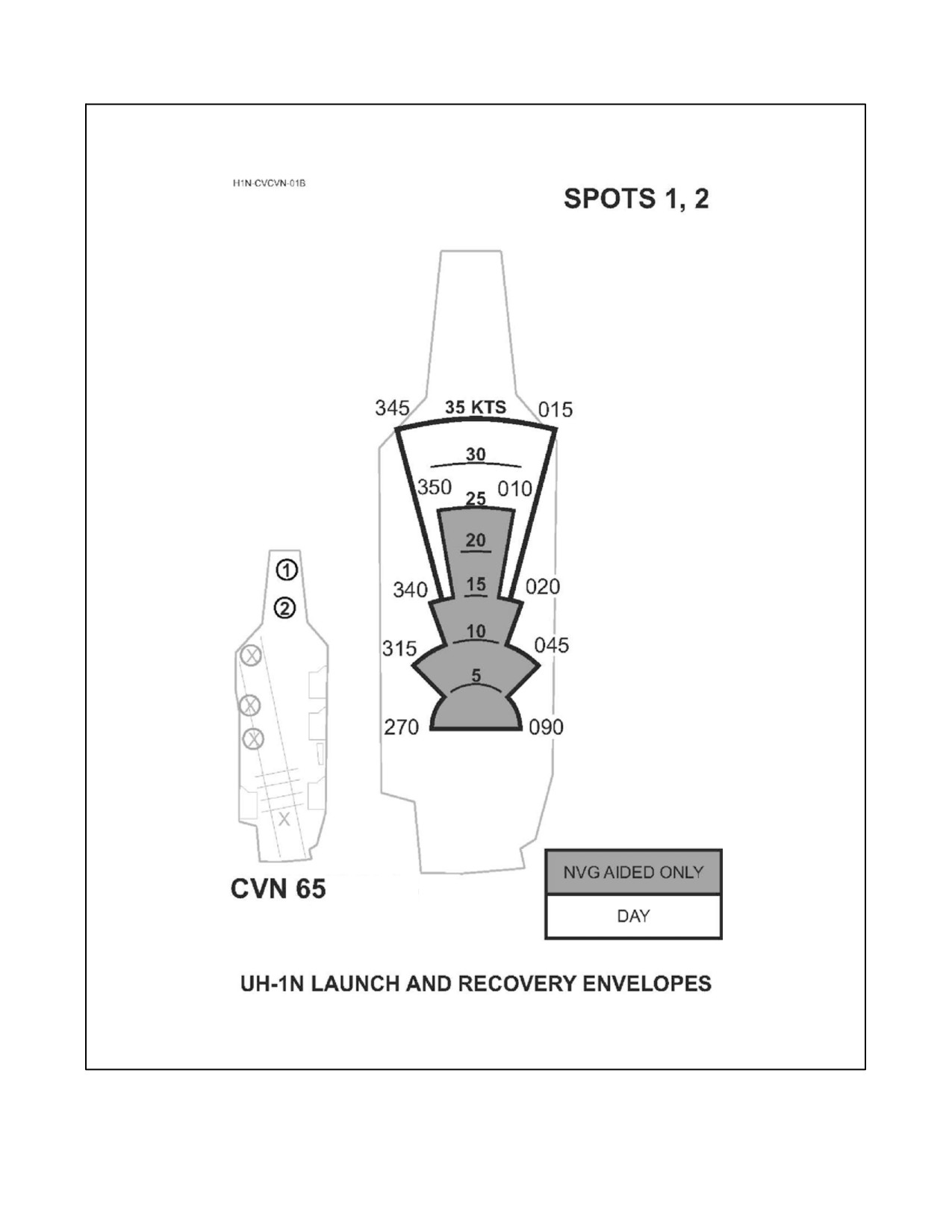
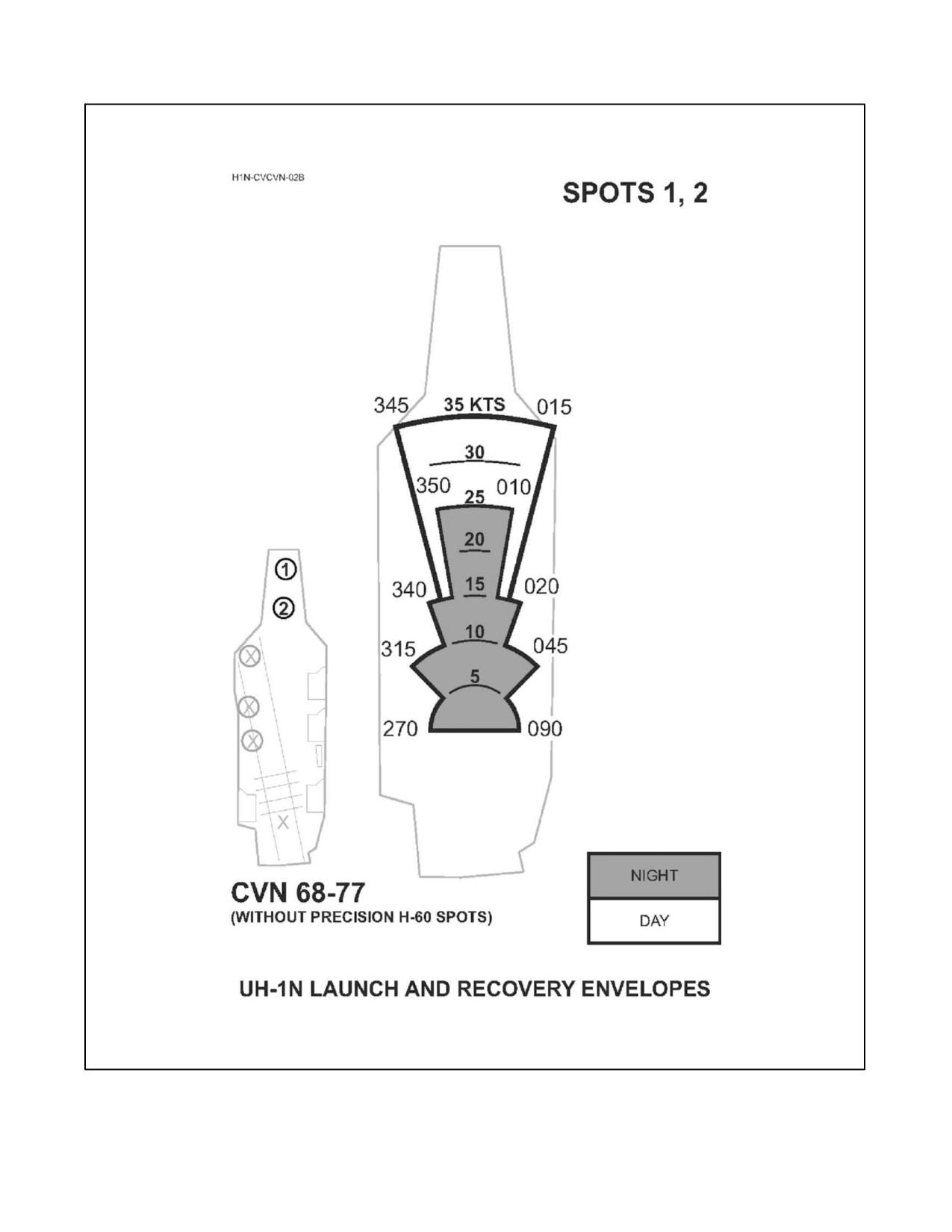
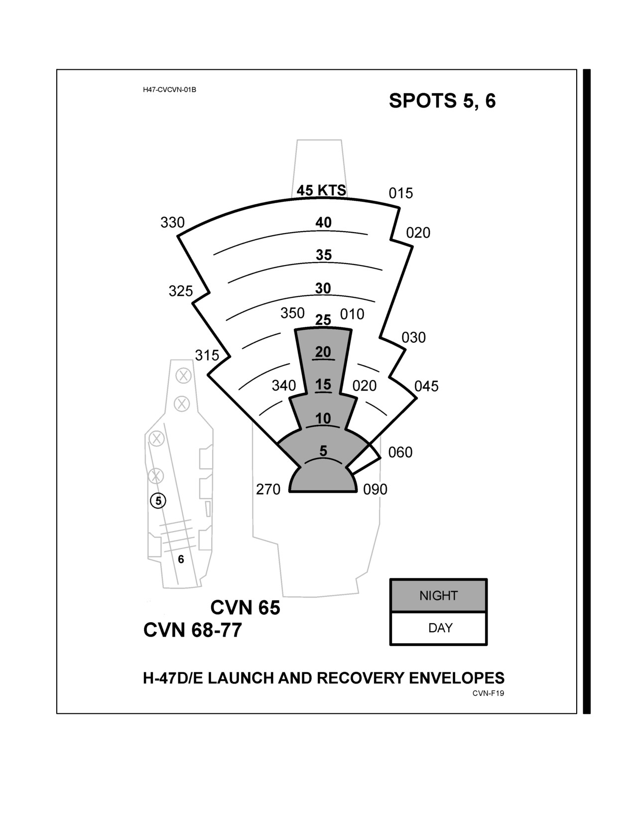
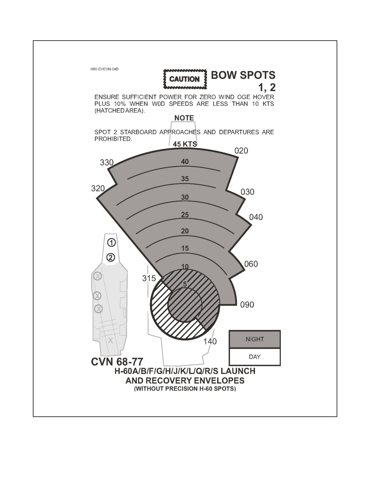
Launch and recovery wind envelopes for all helicopter spots on CV/CVN class ships are contained in this appendix.
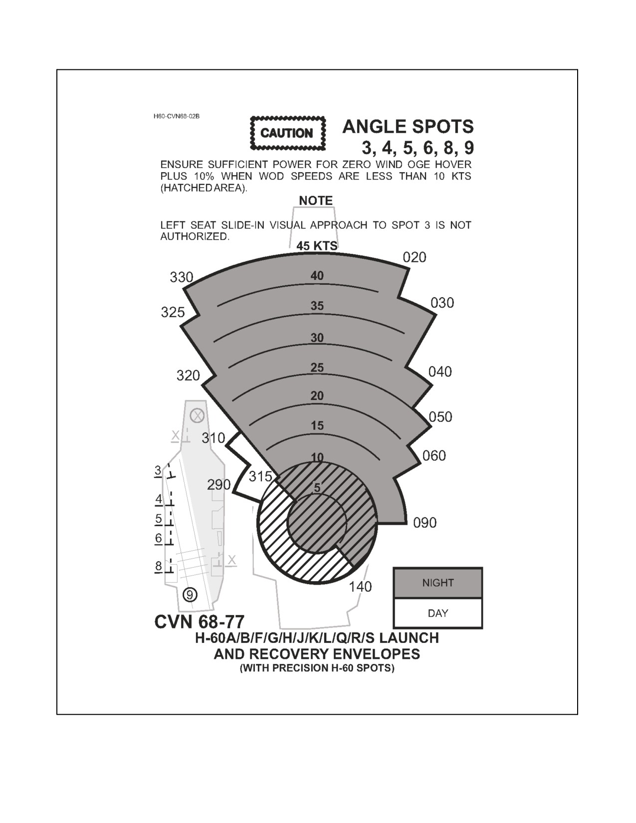
Individually, the envelopes show the maximum wind speed and direction allowed for launching and recovering each
type of helicopter from each shipboard spot with acceptable margins for safety. Collectively, the envelopes provide
a broad inventory of launch and recovery wind envelopes for helicopters operating from CV/CVN flight decks.
Helicopter spot locations are published in Appendix B. Used together, Appendixes B and C provide a full array of
launch and recovery options for use during carrier operations. Although some wind limits are noticeably restrictive,
they are the only ones presently available based on tested data.
C.2
LAUNCH AND RECOVERY WIND ENVELOPE FEATURES
The features built into the launch and recovery wind envelopes in this manual are intended to provide commanding
officers with a broad menu of safe operating envelopes and allow maximum flexibility during the conduct of flight
deck operations. These envelopes incorporate many features. Unless otherwise specified, the envelopes:
1.
Are based on steady state winds measured by the ship’s windward mast mounted anemometer.
Limiting velocities on the wind charts represent maximums for steady state, non-turbulent winds. During
gusty wind conditions and/or pitching decks, if the gust spread is over 10 knots or more, reduce the maximum
winds allowed for rotor engagement and disengagement by 10 knots for all quadrants.
Note
Considerable difference may exist between the actual flight deck winds and
those measured by the mast-mounted anemometers.
2.
Are defined relative to the ship’s centerline.
3.
Are valid for helicopter landing spots identified in Appendix B as indicated on the wind envelope.
4.
Are valid for normal approach to the stop, with the helicopter aligned with the ship’s centerline, angle, or
designated line-up line at touchdown.
5.
Are valid for all certified lighting configurations.
6.
Are shaded to distinguish day limits from night limits.
7.
Are valid for the PAC in either seat.
8.
Are valid for all NATOPS-approved loading configurations, GW, and CG conditions, provided power
available exceeds power required to hover out of ground effect.
C-1
ORIGINAL

NAVAIR 00-80T-105
Note
For most ships, aircraft NATOPS zero wind HOGE torque is often the best
approximation to shipboard hover torque requirements for all wind
conditions; however, an additional power margin of 5 to 10 percent may be
required to approach, overcome turbulence, decelerate, or depart the
vicinity of the flight deck. Envelope regions exhibiting hover requirement
in excess of NATOPS zero wind HOGE torque requirements are identified
in an appropriate note on the wind envelope.
9. Notes pertinent to a specific aircraft/spot combination are presented on the applicable wind envelope.
C.3
WIND LIMIT ORIENTATION
When the wind limits for a particular aircraft are shown, they are the maximum allowable wind speed and direction
over the deck relative to the ship for launch and recovery. When the limits for a particular helicopter and the landing
location are not shown, use of the general wind envelope in Figure C-1 is mandatory. Unlike wind envelopes shown
for a specific helicopter, the generic wind limits in Figure C-1 are oriented relative to the aircraft’s nose at touchdown,
instead of being oriented relative to the ship’s centerline.
C.4
OTHER SOURCES OF HELICOPTER WIND ENVELOPES
Copies of applicable envelopes appearing in this manual are also published in the NATOPS Pocket Checklist of each
helicopter.
C.5
USE OF NOTES IN WIND ENVELOPES
Because room on the launch and recovery wind envelope is scarce, the standard labeling for warnings, cautions and
notes can more than fill the remaining space. To mitigate this problem, all notations that include restrictions are
marked on the wind envelopes in the form of Notes, even though they may involve warning or caution material.
Therefore, it is imperative that all of the information on a wind envelope be reviewed thoroughly before the envelope
is used.
C.6
QUESTIONS AND COMMENTS ON WIND ENVELOPES
Comments/questions about the wind envelopes should be submitted directly to COMNAVAIRSYSCOM (AIR-4.0P)
via the Airworthiness Issues Resolution System (AIRS) which may be accessed online via the Airworthiness website
at https://airworthiness.navair.navy.mil. In the event the internet is not available to you, you may mail your questions
and comments to:
Commander
Naval Air Systems Command (Air-4.0P)
22244 Cedar Point Rd, Bldg 460, Rm 228
Patuxent River, MD 20670-1163
ORIGINAL
C-2

NAVAIR 00-80T-105
Figure C-1. CV/CVN Launch and Recovery Envelopes for Helicopter Combinations Not Listed Elsewhere
C-3
ORIGINAL
NAVAIR 00-80T-105
Figure C-2. UH-1N Launch and Recovery Envelopes for CVN 65 Spots 1 & 2
ORIGINAL
C-4
NAVAIR 00-80T-105
Figure C-3. UH-1N Launch and Recovery Envelopes for CVN 68−77 Spots 1 & 2
C-5
ORIGINAL

NAVAIR 00-80T-105
Figure C-4. UH-1N Launch and Recovery Envelopes for CVN 65 & CVN 68−77 Spots 3, 4, 5, & 6
ORIGINAL
C-6

NAVAIR 00-80T-105
Figure C-5. UH-1N Launch and Recovery Envelopes for CVN 68−77 Spots 1 & 2
C-7
ORIGINAL

NAVAIR 00-80T-105
Figure C-6. UH-1N Launch and Recovery Envelopes for CVN 68−77 Spots 4, 5, 6, & 9
ORIGINAL
C-8
NAVAIR 00-80T-105
Figure C-7. H-47 Launch and Recovery Envelope for CVN 65 Angle Spots
(including CVN 68-77 without precision H-60 spots)
C-9
ORIGINAL

NAVAIR 00-80T-105
Figure C-8. H-47 Launch and Recovery Envelope for CVN 67−77 Angle Spots
(with precision H-60 spots)
ORIGINAL
C-10

NAVAIR 00-80T-105
Figure C-9. H-53 Launch and Recovery Envelopes for CVN 65 Spots 1 & 2
C-11
ORIGINAL

NAVAIR 00-80T-105
Figure C-10. H-53 Launch and Recovery Envelopes for CVN 68−77 Spots 1 & 2
ORIGINAL
C-12

NAVAIR 00-80T-105
Figure C-11. H-53 Launch and Recovery Envelopes for CVN 65 & CVN 68−77 Spots 3, 4, 5, & 6
C-13
ORIGINAL

NAVAIR 00-80T-105
Figure C-12. H-53 Launch and Recovery Envelopes for CVN 68−77 Spots 1 & 2
ORIGINAL
C-14

NAVAIR 00-80T-105
Figure C-13. H-53 Launch and Recovery Envelopes for CVN 68−77 Spots 4, 5, 6, & 9
C-15
ORIGINAL

NAVAIR 00-80T-105
Figure C-14. H-60 Launch and Recovery Envelopes for CVN 65 Bow Spots 1 & 2
ORIGINAL
C-16

NAVAIR 00-80T-105
Figure C-15. H-60 Launch and Recovery Envelopes for CVN 65 Angle Spots 3, 4, & 5
C-17
ORIGINAL

NAVAIR 00-80T-105
Figure C-16. H-60 Launch and Recovery Envelopes for CVN 65 AFT Spot 6
ORIGINAL
C-18
NAVAIR 00-80T-105
Figure C-17. H-60 Launch and Recovery Envelopes for CVN 68-77 Bow Spots 1 & 2
C-19
ORIGINAL

NAVAIR 00-80T-105
Figure C-18. H-60 Launch and Recovery Envelopes for CVN 68-77 Angle Spots 3, 4, 5, & 6
ORIGINAL
C-20

NAVAIR 00-80T-105
Figure C-19. H-60 Launch and Recovery Envelopes for CVN 68-77 Bow Spots 1 & 2
C-21
ORIGINAL
NAVAIR 00-80T-105
Figure C-20. H-60 Launch and Recovery Envelopes for CVN 68-77 Angle Spots 3, 4, 5, 6, 8, & 9
ORIGINAL
C-22

NAVAIR 00-80T-105
Figure C-21. H-60 Launch and Recovery Envelopes for CVN 68-77 Spot 7
C-23/(C-24 blank)
ORIGINAL
NAVAIR 00-80T-105
INDEX
Page
Page
No.
No.
A
Visual signals to aircraft from ship
under EMCON or lost communication
Abort/strikedown
7-17
conditions
6-31
Additional requirements
2-1
Visual signals to ship from aircraft
Advisory control
4-3
with radio failure
6-31
Air:
Alert aircraft requirements
5-24
Condition helicopters
5-25
Officer
4-1, 6-25
Fixed wing condition aircraft
5-25
Operations officer
4-1
All aircraft except helicopters
6-18
Transfer officer
3-8
All personnel
2-2
Aircraft:
Approach(es):
Alert aircraft requirements
5-24
Approach minimums
6-9
Alone
6-19
Communication or NAVAID failure
All aircraft except helicopters
6-18
during approach
6-19
Changes in pilot or aircraft assignments
3-8
Compulsory arrival, marshal,
COD aircraft starboard holding
6-2
and approach voice reports
6-20
COD/VOD
5-2
Downwind leg and approach turn
6-3
Control of departing
5-26
En route radar approaches
6-7
Diversion of
6-40
Failure of carrier navigation aids/
Downed
5-23
CATCC radars prior to approach
6-20
Downed and standby
5-23
ICLS
6-17
Fixed-wing
6-29, 6-31
Instrument approach procedures
6-9
Fixed wing aircraft readiness conditions
5-25
Minimums
6-9
Fixed-wing condition
5-25
Nonprecision approach
6-17
Fueling and defueling
7-8
NVD equipment aided approaches
6-27
Helicopter aircraft readiness conditions
5-25
PALS Mode I approach (with
AN/ARA-63/AN/ARN-138 monitor)
6-14
In company
6-20
PALS Mode IA approach
Jet
5-28, 5-29
(ILM not required)
6-15
Jet/turboprop
5-28, 6-6
PALS Mode II approach
Jet/turboprop aircraft port holding/
(ILM not required)
6-16
spin pattern
6-2
PALS Mode IID approach
Launch of condition fixed wing
5-25
(ILM not required)
6-16
Launching fixed-wing
5-2
PALS Mode III approach
6-16
Maintenance on loaded
7-17
Aqueous film forming foam (AFFF) system
Manning
5-2
and mobile firefighting equipment
3-2
Movement of
7-2
Area, Entering the carrier control
6-1
Recovering fixed-wing
6-21
Arming
7-13
Report of damage to
7-7
Arrival procedures
6-1
Security
7-7
Arrival information
6-1
Standby
5-23
Entering the carrier control area
6-1
Turboprop
5-28, 5-29
Transient helicopters
6-1
Index-1
ORIGINAL
NAVAIR 00-80T-105
Page
Page
No.
No.
B
Catapult:
Hangfire
5-13
Basic procedures
4-6
Launching
5-5
Bow-on-recovery
6-7
Suspend
5-12
Briefing
3-7, 7-1
CATCC
4-5
CDC
4-5
Changes in pilot or aircraft assignments
3-8
C
Close proximity operations
3-8
COD:
Carrier pattern emergencies
6-32
/VOD aircraft
5-2
Case I
6-1
Aircraft starboard holding
6-2
/II
6-32
Combat direction center officer
4-2
And case II
5-30
Command, NATOPS cognizant
1-3
COD aircraft starboard holding
6-2
Commanding officers
1-3
Departure
5-28
Communication:
Drag
6-5
Communication control
4-5
Helicopters
6-3
Communication or NAVAID failure
Jet/turboprop aircraft port holding/
during approach
6-19
spin pattern
6-2
Communication security
4-6
Rendezvous
5-28
Day communication emergencies
6-32
VFR day fixed wing carrier landing pattern . .
6-3
Departure communication procedures
5-27
Night communication emergencies
6-32
Voice reports
6-5
Visual signals to aircraft from ship under
ZIP LIP
6-5
EMCON or lost communication
Case II
6-5
conditions
6-31
/III rendezvous
5-29
Voice communication procedures
6-20
Departure
5-28
Communication control
4-5
Case III
5-30, 6-6, 6-39
Communication security
4-6
Communication or NAVAID failure
Control of radio circuits
4-5
during approach
6-19
Recording of radio circuits
4-6
Delta procedures
6-17
Voice procedures
4-5
Departing marshal
6-8
Communication or NAVAID failure
Departure
5-29
during approach
6-19
Departure voice reports
5-27
Aircraft alone
6-19
Frequency/IFF/SIF changes
6-8
Aircraft in company
6-20
Failure of carrier navigation aids/CATCC
General instructions
6-8
radars prior to approach
6-20
Initial separation
6-8
Compulsory arrival, marshal, and approach
Instrument approach procedures
6-9
voice reports
6-20
Marshal instructions
6-7
Condition helicopters
5-25
Marshal procedures
6-6
Helicopter aircraft readiness conditions
5-25
Missed approach/waveoff/bolter
6-17
Launch of condition helicopters
5-26
Night EMCON recovery
6-18
Condition:
Radar handoff procedures
6-20
I
5-25
Voice communication procedures
6-20
II
5-25, 5-26
Index-2
ORIGINAL
NAVAIR 00-80T-105
Page
Page
No.
No.
III
5-25, 5-26
D
IV
5-25, 5-26
Day communication emergencies
6-32
Control:
Dearming
7-15
Advisory
4-3
Deck:
Authority
4-7
Flight deck procedures
6-23
Communication
4-5
Launching
5-18
Criteria
4-2
Recommended deck lighting configuration
Degrees of control
4-2
for helicopter NVD aided takeoff
Electronic emission control
4-3
and landing
5-22, 6-28
Emergency control procedures
4-6
Degrees of control
4-2
Entering the carrier control area
6-1
Advisory control
4-3
Fuel transfer and dump control
6-40
Monitor control
4-3
Initial control responsibility
4-6
Nonradar control
4-3
Monitor control
4-3
Positive control
4-2
Nonradar control
4-3
Delta procedures
6-17
Departing marshal
6-8
Of departing aircraft
5-26
Departure communication procedures
5-27
Of radio circuits
4-5
Case III departure voice reports
5-27
Of the landing pattern (VMC)
6-25
Launch frequencies
5-27
Positive control
4-2
Lost communications during departures
5-27
Control criteria
4-2
Single-frequency departures
5-27
Degrees of control
4-2
Departure radials
5-27
Electronic emission control
4-3
Diversion of aircraft
6-40
Control of departing aircraft
5-26
Downed and standby aircraft
5-23
Departure communication procedures
5-27
Downwind leg and approach turn
6-3
Departure radials
5-27
Drag
6-5
Fixed-wing departures/rendezvous
5-28
Helicopter departure
5-30
E
Control of radio circuits
4-5
CATCC
4-5
Electronic emission control
4-3
CDC
4-5
Elevator operation
7-6
Prifly
4-5
Emergency(ies):
Control of the landing pattern (VMC)
6-25
After launch
5-24
Air officer
6-25
Carrier pattern emergencies
6-32
LSO (under the supervision
Control procedures
4-6
of the air officer)
6-26
Day communication emergencies
6-32
Correcting to the final bearing
6-9
ICCS emergency procedures
5-12
Crewmembers, Flight
2-2
Landing
6-31
Criteria:
Marshal fixes
6-6
Control
4-2
Night communication emergencies
6-32
Rescue helicopter launching
5-22
Procedures
7-18
Separation
4-4
Signals
6-31
Index-3
ORIGINAL
NAVAIR 00-80T-105
Page
Page
No.
No.
Emergency after launch
5-24
Case II departure
5-28
Night/instrument meteorological
Case II/III rendezvous
5-29
conditions
5-24
Case III departure
5-29
Visual meteorological conditions
5-24
Fixed-wing IMC at altitude
5-29
Emergency control procedures
4-6
Fixed-wing aircraft
6-29, 6-31
Basic procedures
4-6
Fixed-wing IMC at altitude
5-29
Initial control responsibility
4-6
Flight:
Emergency landing
6-31
Crewmembers
2-2
Fixed-wing aircraft
6-31
Deck procedures
6-23
Helicopters
6-31
Plans and advisories
3-7
Emergency signals
6-31
Quarter stations
3-2
Carrier pattern emergencies
6-32
Flight plans and advisories
3-7
Day communication emergencies
6-32
Close proximity operations
3-8
Night communication emergencies
6-32
Flight quarter stations
3-2
Visual signals to aircraft from ship under
Aqueous film forming foam (AFFF) system
EMCON or lost communication
and mobile firefighting equipment
3-2
conditions
6-31
Preliminary procedures — air officer
3-3
Visual signals to ship from aircraft
Preliminary procedures — CATCC
3-3
with radio failure
6-31
Frequency/IFF/SIF changes
6-8
En route radar approaches
6-7
Fuel transfer and dump control
6-40
Engine start and turnup
5-2
Fueling and defueling aircraft
7-8
Entering the carrier control area
6-1
Fueling and defueling
7-9
Entry, Landing pattern
6-3
Hot refueling
7-9
Equipment
7-2
Aqueous film forming foam (AFFF) system and
G
mobile firefighting equipment
3-2
NVD equipment aided approaches
6-27
General instructions
6-8
General requirements
7-1
Good azimuth and good dme
5-28
F
Good azimuth and no dme
5-28
Failure:
Groove and touchdown
6-3
Communication or NAVAID failure
during approach
6-19
H
Failure of carrier navigation aids/
CATCC radars prior to approach
6-20
Helicopter(s)
6-3, 6-6, 6-18, 6-30, 6-31
Visual signals to ship from aircraft
Aircraft readiness conditions
5-25
with radio failure
6-31
Launch procedures
5-19
Final preparations for launch
5-3
Procedures
7-18
Fixed wing condition aircraft
5-25
Safety precautions
5-20
Fixed wing aircraft readiness conditions
5-25
Helicopter departure
5-30
Launch of condition fixed wing aircraft
5-25
Case I and case II
5-30
Fixed-wing departures/rendezvous
5-28
Case III
5-30
Case I departure
5-28
Hot refueling
7-9
Case I rendezvous
5-28
Hung/unexpended weapons
7-15
Index-4
ORIGINAL
NAVAIR 00-80T-105
Page
Page
No.
No.
I
Signal officer
4-1
Signalman enlisted
4-1
ICCS catapult launch procedures
5-7
Special procedures for carrier
ICCS catapult safety precautions
5-14
qualification landing
6-29
ICCS emergency procedures
5-12
VFR day fixed wing carrier landing pattern . .
6-3
ICCS emergency procedures
5-12
Lateral separation
4-4
Catapult hangfire
5-13
Launch:
Catapult suspend
5-12
Of condition fixed wing aircraft
5-25
ICLS approach
6-17
Of condition helicopters
5-26
ILARTS special events coverage
7-8
Emergency after
5-24
Initial control responsibility
4-6
Final preparations for
5-3
Initial separation
6-8
Frequencies
5-27
Instrument approach procedures
6-9
Helicopter launch procedures
5-19
Approach minimums
6-9
ICCS catapult launch procedures
5-7
Correcting to the final bearing
6-9
Intent to launch weapons
7-14
ICLS approach
6-17
Non-ICCS catapult launch procedures
5-15
Nonprecision approach
6-17
And recovery wind envelope features
C-1
PALS Mode I approach (with
Launching fixed-wing aircraft
5-2
AN/ARA-63/AN/ARN-138 monitor)
6-14
Catapult launching
5-5
PALS Mode IA approach
Engine start and turnup
5-2
(ILM not required)
6-15
Final preparations for launch
5-3
PALS Mode II approach
Taxiing
5-4
(ILM not required)
6-16
Launching helicopters
5-19
PALS Mode IID approach
Helicopter launch procedures
5-19
(ILM not required)
6-16
Helicopter safety precautions
5-20
PALS Mode III approach
6-16
Recommended deck lighting configuration
Penetration/approach
6-9
for helicopter NVD aided takeoff
Intent to launch weapons
7-14
and landing
5-22
Lost communications during departures
5-27
J
Low visibility voice reports: anyone
can recommend low visibility reports
6-5
Jet aircraft
5-28, 5-29
LSO (under the supervision of
Jet/turboprop aircraft
5-28, 6-6
the air officer)
6-26
Port holding/spin pattern
6-2
M
L
Maintenance:
Landing:
Liaison
7-1
Control of the landing pattern (VMC)
6-25
On loaded aircraft
7-17
Emergency
6-31
Personnel
2-2
Pattern departure
6-3
Manning aircraft
5-2
Pattern entry
6-3
Marshal:
Pattern upwind leg
6-3
Airspeed
6-7
Recommended deck lighting configuration
Altitude assignment
6-7
for helicopter NVD aided takeoff
Altitude separation
6-7
and landing
5-22, 6-28
Instructions
6-7
Index-5
ORIGINAL
NAVAIR 00-80T-105
Page
Page
No.
No.
Marshal procedures
6-6
Night EMCON recovery
6-18
Bow-on-recovery
6-7
All aircraft except helicopters
6-18
Emergency marshal fixes
6-6
Helicopters
6-18
En route radar approaches
6-7
Non-ICCS catapult launch procedures
5-15
Nonprecision approach
6-17
Helicopters
6-6
Nonradar control
4-3
Jet/turboprop aircraft
6-6
NVD equipment aided approaches
6-27
Marshal airspeed
6-7
Marshal altitude assignment
6-7
O
Marshal altitude separation
6-7
Overhead marshal
6-6
Officer(s):
Air
4-1, 6-25
Missed approach/waveoff/bolter
6-17
Air operations
4-1
Mode:
Air transfer
3-8
Mode I launching procedures
5-15
Combat direction center
4-2
PALS Mode I approach (with
Commanding
1-3
AN/ARA-63/AN/ARN-138 monitor)
6-14
Landing signal
4-1
PALS Mode IA approach
Operations
4-1
(ILM not required)
6-15
Preliminary procedures — air
3-3
PALS Mode II approach
Operations:
(ILM not required)
6-16
Air operations officer
4-1
PALS Mode IID approach
(ILM not required)
6-16
Close proximity
3-8
Officer
4-1
PALS Mode III approach
6-16
Rescue helicopter
5-22
Monitor control
4-3
Tanker
6-32
Movement:
Ordnance personnel
2-3
Of aircraft
7-2
Other relevant publications
1-1
Weapon movement
7-11
Other sources of helicopter wind envelopes
C-2
Movement of aircraft
7-2
Overhead marshal
6-6
Aircraft security
7-7
Elevator operation
7-6
P
ILARTS special events coverage
7-8
PALS:
Report of damage to aircraft
7-7
Mode I approach (with
AN/ARA-63/AN/ARN-138 monitor)
6-14
N
Mode IA approach (ILM not required)
6-15
Mode II approach (ILM not required)
6-16
NATOPS:
Mode IID approach (ILM not required)
6-16
Advisory group
1-3
Mode III approach
6-16
Cognizant command
1-3
Passenger transfers
3-9
Model manager
1-3
Penetration/approach
6-9
Navigation, Failure of carrier navigation aids/
Personnel:
CATCC radars prior to approach
6-20
All
2-2
Night:
Maintenance
2-2
/Instrument meteorological conditions
5-24
Ordnance
2-3
Communication emergencies
6-32
Phraseology
6-21
Index-6
ORIGINAL
NAVAIR 00-80T-105
Page
Page
No.
No.
Pilots
4-2
Recovery
6-26
Plane:
Recovery tanker
6-32
Captains
2-2
Rendezvous
6-39
Guard station
4-7
SAR helicopter
4-7
Plane guard helicopter
4-7
Special procedures for carrier
qualification landing
6-29
Control authority
4-7
Voice
4-5
Plane guard station
4-7
Voice communication
6-20
Restrictions
4-7
Weapon handling
7-10
Search and rescue
4-7
Positive control
4-2
Q
Predeployment lecture syllabus
2-2
All personnel
2-2
Qualification, Special procedures
Flight crewmembers
2-2
for carrier qualification landing
6-29
Maintenance personnel
2-2
Questions and comments on wind envelopes . . . C-2
Ordnance personnel
2-3
R
Plane captains
2-2
Prelaunch procedures
5-1
Radar handoff procedures
6-20
COD/VOD aircraft
5-2
Radio:
Manning aircraft
5-2
Control of radio circuits
4-5
Preliminary procedures:
Recording of radio circuits
4-6
Air officer
3-3
Visual signals to ship from aircraft
CATCC
3-3
with radio failure
6-31
Preparation for recovery
6-21
Recommended deck lighting configuration
for helicopter NVD aided takeoff
PriFly
4-5
and landing
5-22, 6-28
Procedures:
Recording of radio circuits
4-6
Arrival
6-1
Recovering fixed-wing aircraft
6-21
Basic
4-6
Control of the landing pattern (VMC)
6-25
Delta
6-17
Flight deck procedures
6-23
Departure communication
5-27
Special safety precautions
6-23
Emergency
7-18
Recovering helicopters
6-26
Emergency control
4-6
NVD equipment aided approaches
6-27
Flight deck
6-23
Recommended deck lighting configuration
Helicopter
7-18
for helicopter NVD aided takeoff
Helicopter launch
5-19
and landing
6-28
ICCS catapult launch
5-7
Recovery procedures
6-26
ICCS emergency
5-12
Special safety precautions
6-28
Instrument approach
6-9
Recovery:
Marshal
6-6
Case III
6-39
Mode I launching
5-15
Launch and recovery wind
Non-ICCS catapult launch
5-15
envelope features
C-1
Prelaunch
5-1
Preparation for
6-21
Preliminary procedures — air officer
3-3
Procedures
6-26
Preliminary procedures — CATCC
3-3
Tanker procedures
6-32
Radar handoff
6-20
Tanking pattern
6-39
Index-7
ORIGINAL
NAVAIR 00-80T-105
Page
Page
No.
No.
Refueling, Hot
7-9
S
Rendezvous:
SAR:
High/on top (day and night)
6-39
Helicopter procedures
4-7
Low (day and night)
6-39
Requirements
4-7
Procedures
6-39
Response
4-7
Report of damage to aircraft
7-7
Scope
1-1
Reports:
Search and rescue
4-7
Case III departure voice reports
5-27
SAR helicopter procedures
4-7
Compulsory arrival, marshal, and
SAR requirements
4-7
approach voice reports
6-20
SAR response
4-7
Separation criteria
4-4
Low visibility voice reports: anyone can
recommend low visibility reports
6-5
Lateral separation
4-4
Vertical separation
4-5
Voice reports
6-5
Single-frequency departures
5-27
Requirements:
Special procedures for carrier
Additional
2-1
qualification landing
6-29
Alert aircraft
5-24
Fixed-wing aircraft
6-29
General
7-1
Helicopters
6-30
SAR
4-7
Special safety precautions
6-23, 6-28
Training
2-1
Standby aircraft
5-23
Rescue helicopter:
Station(s):
Launching criteria
5-22
Flight quarter
3-2
Mission information
5-23
Plane guard
4-7
Operations
5-22
Syllabus, Predeployment lecture
2-2
Responsibilities
1-3, 4-1
T
Air officer
4-1
Tanker operations
6-32
Air operations officer
4-1
Fuel transfer and dump control
6-40
Combat direction center officer
4-2
Recovery (case III)
6-39
Commanding officers
1-3
Recovery tanker procedures
6-32
Initial control
4-6
Recovery tanking pattern
6-39
Landing signal officer
4-1
Rendezvous procedures
6-39
Landing signalman enlisted
4-1
Taxiing
5-4
NATOPS advisory group
1-3
Training
1-3
NATOPS cognizant command
1-3
Requirements
2-1
NATOPS model manager
1-3
Transient helicopters
6-1
Operations officer
4-1
Turboprop aircraft
5-28, 5-29
Pilots
4-2
U
Respot forward
5-24
Restrictions
4-7
Use of notes in wind envelopes
C-2
Index-8
ORIGINAL
NAVAIR 00-80T-105
Page
Page
No.
No.
V
Weapon(s):
Definitions
7-10
Vertical:
Intent to launch
7-14
Replenishment
7-8
Loading/downloading
7-12
Separation
4-5
Movement
7-11
VFR day fixed wing carrier landing pattern
6-3
Weapon handling procedures
7-10
Downwind leg and approach turn
6-3
Abort/strikedown
7-17
Groove and touchdown
6-3
Arming
7-13
Landing pattern departure
6-3
Dearming
7-15
Landing pattern entry
6-3
Emergency procedures
7-18
Landing pattern upwind leg
6-3
Helicopter procedures
7-18
Waveoffs
6-3
Hung/unexpended weapons
7-15
Visual meteorological conditions
5-24
Intent to launch weapons
7-14
Visual signals to aircraft from ship under EMCON
Maintenance on loaded aircraft
7-17
or lost communication conditions
6-31
Weapon definitions
7-10
Visual signals to ship from aircraft with
Weapon loading/downloading
7-12
radio failure
6-31
Voice communication procedures
6-20
Weapon movement
7-11
Compulsory arrival, marshal,
Wind:
and approach voice reports
6-20
Launch and recovery wind
Phraseology
6-21
envelope features
C-1
Preparation for recovery
6-21
Other sources of helicopter
wind envelopes
C-2
Voice procedures
4-5
Questions and comments on
Voice reports
6-5
wind envelopes
C-2
Low visibility voice reports: anyone can
Use of notes in wind envelopes
C-2
recommend low visibility reports
6-5
Wind limit orientation
C-2
W
Z
Waivers
1-3
Waveoffs
6-3
ZIP LIP
6-5
Index-9/(10 blank)
ORIGINAL