Military reference books and manuals (2009-2023, Volume 2) - page 52

NAVAIR 00-80T-105
TYPE OF FAILURE
FLIGHT CONDITIONS
Transmitter failure with or with-
VMC
*IMC
out receiver failure (navigation
1.
Join up if possible.
1.
Transition to VMC if possible and
aids serviceable).
continue VMC.
2.
Maintain VMC.
2.
Proceed to emergency marshal.
a. Enter VMC landing
3.
Squawk Mode III 7600, “IDENT,”
pattern.
and Mode 1 in accordance with
Figure 4-2.
b. Use standard visual
4.
Watch for joinup.
signals when in range of
ship.
c. Watch for light signals
5.
Hold at emergency marshal until
from ship.
EEAT.
3.
Squawk Mode III 7600,
6.
Commence approach at EEAT.
“IDENT,” and Mode I in
Squawk in accordance with
accordance with Figure 4-2.
Figure 4-2.
4.
In receiving, follow
7.
If receiving, follow instructions.
instructions.
5.
Broadcast intentions period-
8.
Broadcast intentions periodically
ically, whether or not trans-
whether or not transmitter is known
mitter is known to be
to be serviceable.
serviceable.
6.
Tune in parent CV data-link
9.
Tune in parent CV data-link
frequency.
frequency.
Navigation aids and transmitter
1.
Perform same procedures
1.
Transition to VMC if possible and
failures, with or without receiver
as for communications fail-
maintain VMC.
failure.
ure, or
2.
When position is unknown:
2.
Navigate by DR to best position.
a. Navigate by DR to best
3.
Squawk in accordance with Figure
position.
4-2 or EMERGENCY as required.
b. Squawk in accordance
4.
Fly appropriate triangles.
with Figure 4-2 or
EMERGENCY as
required.
c. Fly appropriate
5.
Watch for joinup.
triangles.
d. Watch for join up.
6.
If receiving, follow instructions.
3.
Tune in parent CV data link
7.
Broadcast intentions periodically
frequency.
whether or not transmitter is known
to be serviceable.
4.
If all above fails, bingo to
8.
Tune in parent CV data-link
nearest suitable field at
frequency.
appropriate fuel state.
*
All procedures are for single aircraft. When in company, VMC or IMC, remain in company and use hand
signals between aircraft.
Figure 4-1. Basic Emergency Procedures for Communication/Navigational Equipment Failure
ORIGINAL
4-8
NAVAIR 00-80T-105
Mode III — Lost communications (transmitter and/or receiver) squawk Code 7600. Emergencies squawk 7700.
Mode I — The following codes will amplify difficulties in conjunction with a Code 7600 or 7700. No receiver shall
mean that the primary UHF, auxiliary receiver, and UHF/VHF Guard receiver are inoperative. If any receiver is
operative, the controller is capable of controlling the aircraft utilizing IFF standby squawks and/or aircraft turns
to acknowledge receipt of instructions.
Note
Below 2,500 feet, pilots must be aware of the dangers of changing IFF codes.
1. HEFOE Squawks
Mode I
Mode III
First digit
Second digit
0 — OK
0 — No radio reception PALS/ILM
OK
1 — No radio reception, TACAN OK
1 — Hydraulic
7700/7600 (with HEFOE code, use
Code 7700)
2 — Electrical
2 — No radio reception, ADF OK
3 — Fuel
3 — Radio reception, OK, no
NAVAIDs
4 — Oxygen
5 — Engine
2. Assistance Required Squawks
All 7 — Mode I squawks indicate no receiver and no NAVAID(s).
Mode I
Mode III
70 — Desire tanker to join
Fuel on board (up to 7,400)
71 — Intend bingo
72 — Desire aircraft to assist
3. Limited Communication Squawks
Require a 1-minute cycling of Mode III from 7600/7700 to desired channel.
Mode I
Mode III
60 — Aux. Rec. (ADF) channel _____________
Channel usable (0100−2000, and
2100 = Guard)
61 — No NAVAID(s) Rec. on channel ___________
62 — TACAN OK. Rec. on channel ______________
Figure 4-2. Lost Communication Emergency Squawks
4-9
ORIGINAL

NAVAIR 00-80T-105
Figure 4-3. Helicopter Restrictions During Fixed-Wing Launch/Recovery
ORIGINAL
4-10

NAVAIR 00-80T-105
OUTSIDE RANGE OF A
WITHIN RANGE OF SAFE LANDING FIELD
SAFE LANDING FIELD
NIGHT OR LOW
DAY
VISIBILITY
DAY & NIGHT
CARRIER
A or B
A, C or D
(1)
QUALIFICATIONS
FIXED WING
A or B
A, C or D
(1)
CURRENCY
CYCLIC OPERATIONS
A or B
A, C or D
(1)
HELO/OPS SHIP
E
E
E
ANCHORED/BETWEEN
FLIGHT OPS
A. One plane guard helicopter airborne and one helicopter in Condition III (See Note 2).
B. One surface combatant in lifeguard station and one helicopter in Condition III (See Note 2).
C. One plane guard helicopter airborne and one surface combatant in lifeguard station.
D. One helicopter in Condition III (See Note 2) and two surface combatants, one in lifeguard station and
one within UHF radio range.
E. One helicopter in Condition III (See Note 2) and one helicopter in Condition IV.
NOTE
(1) When outside range of a safe landing field, the same rescue unit criteria apply for day and night
except that at least one surface combatant shall normally operate within UHF radio range of each
aircraft carrier under both day and night conditions.
(2) The Rigid Hull Inflatable Boat (RHIB) and crew may be used in place of a helicopter in Condition
III at CV/N CO’s discretion. When so used, the RHIB shall be ready, and the crew assigned and
available.
Figure 4-4. Minimum SAR Requirements
4-11/(4-12 blank)
ORIGINAL
NAVAIR 00-80T-105
CHAPTER 5
Launching Aircraft
5.1
PRELAUNCH PROCEDURES
As early as possible before launch, the catapult officer and deck launching officer shall advise the air officer of the
launch wind requirements. The air officer shall relay this information to the bridge.
The aircraft handling officer shall perform the following prior to each launch or setting of Condition I or II, as
described in paragraph 5.12.
1. Assign aircraft to each event specified on the air plan.
2. Brief key flight and hangar deck personnel on the following:
a. Starting and launching sequence
b. Disposition of downed and spare aircraft
c. Aircraft to be towed or taxied forward after the launch
d. Recovery spot (when a recovery is scheduled to follow the launch).
3. Ensure the air gunner or his designated representative attends the aforementioned brief to comment as
appropriate on ordnance safety precautions or weapon handling procedures incident to the launch and
forthcoming recovery if applicable.
4. Ensure the launch spot is relayed to the ready rooms and inform PriFly, CATCC, and the ready rooms as early
as possible of the side numbers of aircraft assigned for launch.
5. Conduct FOD walkdown (minimum one day/one night and as required).
The flight deck officer or his representative shall tour the flight deck to ensure the following:
1. Propellers, tailpipes, and helicopter rotors have sufficient clearance
2. Each aircraft can be safely taxied from its spot
3. Deck-edge antennas are properly positioned and the jackstaff, flagstaff, bow rails, and stern rails have been
removed and stowed
4. No gear is adrift on the flight deck.
The aviation fuel officer or his designated representative shall ensure all aircraft, including standbys, have been fueled
as prescribed in the air plan. Discrepancies shall be brought to the attention of the aircraft handling officer
immediately.
The air wing weapon officer or his designated representative shall visually inspect each aircraft to ensure ordnance
loading is as prescribed in the ordnance load plan. Discrepancies shall be brought to the attention of the aircraft
handling officer and ordnance handling officer immediately.
5-1
ORIGINAL
NAVAIR 00-80T-105
Note
Under no circumstances shall the launching officer participate in the
removal of protective devices from the catapult track (i.e., slot seals or
buttons). The catapult officer’s primary function is as a final inspector.
The launching officer(s) shall brief the topside catapult crew(s) and ensure all equipment is ready and that sufficient
launching accessories are available to complete the launch. These tasks shall be completed prior to each launch. In
addition, he shall verify fuel and ordnance loading by consultation with aviation fuel and ordnance personnel. He
shall then compute aircraft launch weights.
The pilot shall confirm fuel, ordnance, and gross weights in writing, which will be submitted to flight deck control
prior to man-up time.
5.1.1 Manning Aircraft
Approximately 45 minutes before launch time, flightcrews will be ordered to man aircraft. When called, they shall
proceed to their aircraft via the designated route and conduct preflight inspections as expeditiously as safety permits.
5.1.2 COD/VOD Aircraft
COD/VOD aircraft passengers shall be escorted to and from the aircraft by the ATO or his assistant. The ATO or his
assistant shall remain with the passengers until they have been embarked. Passengers and cargo will not be off-loaded
until the ATO or his assistant is present. Flight deck survival equipment (cranial helmet, goggles, and floatation
equipment) shall not be removed until passengers are well clear of the hazards of the flight deck environment.
D For off-loading passengers and cargo, both engines of the COD should be
shut down. At a minimum, the engine on the same side of the entrance hatch
shall be secured.
D The ramp shall not be opened/closed externally without confirmation from
the aircraft commander.
D The Mk 1 life preserver, vest type (float-coat) with auto inflator unit
assembly is not authorized for use aboard aircraft.
5.2
LAUNCHING FIXED-WING AIRCRAFT
5.2.1 Engine Start and Turnup
Prior to starting engines, the air officer shall issue appropriate orders or information over the flight deck announcing
system to ensure all prestart preparations are completed and all personnel on the flight deck are alerted.
Note
The mechanical latching of weapons on aircraft racks/launchers shall be
completed before the engine(s) on that aircraft is started for launch.
The air officer shall ensure all flight deck personnel are indoctrinated in and adhere to the positioning of aircraft and
aircraft starting units so that the established minimum distances are maintained. Pilots and aircrews shall be made
ORIGINAL
5-2

NAVAIR 00-80T-105
aware of proper positioning criteria. The responsibility for safe starting of all aircraft rests with the air officer. All
personnel shall follow the prescribed procedures when operating aircraft and aircraft starting units. All unsafe starting
conditions shall immediately be called to the attention of cognizant personnel.
Hot exhaust from aircraft and aircraft starting units is a serious hazard when
operating in close proximity to aircraft, aircraft components, fuel,
weapons, equipment, external store CADs, and personnel.
Engines shall be started only on signal and under the positive control of PriFly. During the starting evolution, the
aircraft handling crew shall remove the towbar if necessary for accomplishment of preflight checks and the plane
captain shall assist the pilot as necessary with preflight checks. Towbars shall remain on or in the immediate vicinity
of aircraft parked in the landing area or in a position that fouls the deck until that aircraft is ready for taxi.
Prior to start, ensure nosewheels are not cocked. Cocked nosewheel may
pose a threat to flight deck personnel.
The plane directors shall monitor the aircraft throughout the warmup and checkout period. Control is assumed by
the plane captain for preflight checks only.
Turboprop aircraft shall not be turned up above 1,500 shaft horsepower (SHP) without specific clearance from a flight
deck director. The pilot shall request clearance to turn up by giving his director the one finger turnup signal. The
director, after checking chocks and tiedowns and ensure the area behind the aircraft is clear, shall return the signal,
thereby clearing the pilot for turnup.
Note
Clearance for turnup shall not be given by anyone other than a flight deck
director.
While an engine is turning up at high power, the director shall continuously check the area behind the aircraft. The
pilot shall frequently look at the director to ensure the “all clear” signal is still being given. After completing all
poststart checks, the pilot shall signal the director, indicating the status of the aircraft. The director will relay the signal
to the officer or petty officer in charge of that area of the flight deck.
5.2.2 Final Preparations for Launch
Approximately 15 minutes before launch, the air officer will initiate the following prelaunch checklist:
1. Wind — Verify the estimated wind available for launch and notify bridge of maximum/minimum wind
requirements.
2. List — Check ship’s list to ensure a level deck.
3. Jet blast deflector cooling — Ensure saltwater cooling is functioning on all active JBDs.
5-3
ORIGINAL

NAVAIR 00-80T-105
If aircraft are to be deck launched, the launching officer shall compute the required deck run and confirm it with the
air officer. The catapult launching officer shall inspect the catapult track(s) and adjacent flight deck area to ensure
they are clear of chocks, towbars, or other equipment. By this time, the following personnel should have manned their
launch stations:
1. LSO
2. Arresting gear personnel
3. ILARTS operator
4. Lens operator
5. PALS radar operator
6. Mobile firefighting equipment operators.
5.2.3 Taxiing
Before ordering removal of chocks, directors shall signal for the pilot to hold brakes. It is imperative that the pilot
acknowledge this signal by affirmative nod of the head in the daytime and by a flashlight at night. The flight deck
officer will control the rate at which aircraft are moved toward the catapult(s) or deck launch spot, ensuring a constant
steady flow of traffic while avoiding unnecessary crowding. All taxi signals shall be answered promptly and
accurately unless the pilot considers there is a dangerous situation existing or developing, in which case he shall stop.
D A director shall not leave an aircraft unattended after chocks and tiedowns
have been removed.
D Aircraft shall not be taxied until pretaxi checks and required procedures
prescribed in the appropriate NAVAIR weapon/store loading checklists/
store reliability cards have been completed.
D COD aircraft shall not be unchained until all passengers and aircrew are
strapped into their seats and the aircraft commander has passed the up and
ready signal.
Note
All movement of aircraft shall be under the control of a plane director.
Safety personnel shall be posted as required to assist the director.
If a pilot loses sight of his director, he shall stop immediately. The director shall stay in view of the pilot at all times
and remain stationary while controlling aircraft. If it is necessary to change his position while controlling an aircraft
at night, the director shall signal the pilot to hold brakes. He will continue giving the hold brake signal while moving
expeditiously to the new position, then resume movement of the aircraft.
Control of a taxiing aircraft shall not be passed from one director to another until the receiving director signals by
extending one arm vertically that he is ready to accept control. A director shall not give signals to a pilot who is already
under the control of another director except in an attempt to avert an accident.
ORIGINAL
5-4

NAVAIR 00-80T-105
When a nosewheel tiller/towbar is to be used in taxiing an aircraft, the director shall signal the pilot that a tiller/towbar
is being attached and shall discontinue giving him directional signals. The pilot must then be careful to avoid
differential braking and/or nosewheel steering and use the brakes only for slowing or stopping the aircraft. Nosewheel
steering shall not be engaged with tiller/towbar attached.
CAUTION
Launching fixed wing aircraft while other aircraft are taxied, spotted, or
towed close behind a JBD may cause damage to those aircraft.
Additionally, launching fixed wing aircraft from catapult
#1 with a
helicopter spotted in the vicinity of elevator #1 exposes the helicopter to a
high level of turbulence which may cause significant damage to the
helicopter.
5.2.4 Catapult Launching
Prior to the launch, the launching officer shall relay the minimum and maximum WOD requirements for the
forthcoming launch to the air officer who shall, in turn, advise the bridge.
During CARQUAL operations, the pilot shall transmit aircraft side number, fuel weight, and gross weight during
a two-way radio check. This report is required prior to initial launch, after hot refueling or when pilot switch occurs.
The air officer shall ensure aircraft side number and gross weight is passed to and confirmed by the launching officer.
D During CARQUAL operations, close monitoring of aircraft gross weights
by the air officer, launching officer, pilots, and squadron representatives is
mandatory to ensure operational safety.
D Turboprop aircraft shall not be launched from waist catapults when
jet/turboprop aircraft with engines operating on No.
2 catapult or a
possibility exists that hot exhaust gases from aircraft spotted anywhere on
the flight deck may be ingested into the turboprop engine during launch.
D Squadron aircraft inspectors shall not perform inspections while an aircraft
is taxiing. It is mandatory to remain well clear of rolling tires at all times
to prevent injury.
CAUTION
Aircraft with wing-or pylon-mounted engines shall not be launched from
catapults having only a single panel JBD if aircraft within 200 feet aft of
the JBD are not properly tied down.
In positioning an aircraft on the catapult, the director must be acutely aware of the activities of the catapult crewmen
and control the aircraft’s speed and movement in such a way that personnel safety will not be jeopardized. Pilots must
guard against the tendency to use excessive power that invariably results in roughness and poor control and
jeopardizes launching accessories.
As the aircraft approaches the catapult, the director shall ensure the aircraft is in the takeoff configuration. JBDs shall
be raised as appropriate.
5-5
ORIGINAL

NAVAIR 00-80T-105
CAUTION
All JBD operators/safety observers shall ensure aircraft clearance is
sufficient prior to raising or lowering JBD. Catapult three requires a JBD
safety observer at all times. Bow catapults utilizing JBD deckedge control
boxes require one JBD safety observer per catapult. JBD safety observers
shall be positioned on the furthest side of the JBD away from the operator.
The safety observer will signal the JBD operator with hand/wands when the
aircraft is clear and the JBD can be raised.
For aircraft using the nosegear launch system, the director shall stop the aircraft at the entry wye area of the guide
track. The holdback man shall attach the holdback bar. The director shall signal the pilot and the hookup petty officer
to lower the launch bar.
CAUTION
Aircraft launch bar should not be lowered outside of the entry wye.
Excessive wear, burring, and hangup may occur if the bar passes over the
deck cleat link track onto the entry wye.
Before taxiing past the shuttle, the pilot shall verify the aircraft gross weight by giving a “thumbs up” signal during
the day or a circular motion with a flashlight at night. A “thumbs down” or negative signal will not be used to indicate
disagreement with the gross weight board. If the pilot does not agree with the gross weight, he will request adjustment
as follows.
1. During the day:
a. To raise the gross weight, hold hand flat with palm up and move in a vertical direction, emphasizing the
upward motion.
b. To lower the gross weight, hold hand with palm down and move in a horizontal direction.
2. At night:
a. To raise the gross weight, move flashlight in a vertical direction, emphasizing the upward motion.
b. To lower the gross weight, move flashlight in a horizontal direction.
Note
Weight board will be changed in 500-or 1,000-pound increments in
accordance with applicable aircraft launch bulletins.
When more than two correction steps are required on the weight board or any difficulty is experienced in confirming
the gross weight, the aircraft shall not be launched until positive determination can be made by the air officer and
confirmed by the pilot and launching officer.
ORIGINAL
5-6

NAVAIR 00-80T-105
When an aircraft carrying ordnance requires arming, the aircraft will be taxied into the arming area. Nose-tow aircraft
shall be stopped after the appropriate JBD has been raised and prior to positioning nose-tow launch bar over shuttle
spreader. Prior to arming, aircraft shall be properly configured for flight. The director shall ensure all personnel are
clear and then direct the aircrew’s attention to the ordnance arming supervisor for arming. When the arming has been
completed and the arming crew is clear, the ordnance arming supervisor will signal the pilot with a “thumbs up” signal
(day) or display a vertical sweep with a red, banded wand (night) and then direct the pilot’s attention back to the
director.
As the aircraft is positioned on the catapult, the squadrons’ aircraft inspector shall inspect the aircraft to ensure it is
properly configured and ready for flight. He shall give a “thumbs up” signal (day) or display a blue wand held
vertically (night) to indicate that he considers the aircraft ready for launch. He shall continuously display this signal
at a position from which he is clearly visible to the launching officer. Should the aircraft inspector desire to prevent
the aircraft from being launched, he shall immediately give a “suspend” signal (day) or display a blue wand moved
horizontally (night) to the director or launching officer who has control of the aircraft at the time the discrepancy is
discovered.
Aircraft shall not have nose-tow launch bar over shuttle spreader until the
aircraft is armed and properly configured for flight.
As the ship approaches the launching parameters, the air officer shall monitor the wind repeater and keep the
launching officer(s) advised of the relative wind velocity. Upon receiving permission from the bridge to launch
aircraft, he shall make a final check to ensure relative wind is within the envelope prescribed in the applicable aircraft
launching bulletin. This shall be accomplished before changing the rotating beacon(s) from red to green (this lights
the PriFly “go” light on the catapult officer ICCS console when in use), thereby clearing the launching officer(s) to
begin launching.
5.3
ICCS CATAPULT LAUNCH PROCEDURES
When the launching officer observes the aircraft type, aircraft weight, and side number, he shall set the CSV command
dials on the COC to the setting prescribed in the applicable aircraft launching bulletin. He then relays this information
to the CCP operator, including the appropriate wind value. After the CCP operator verifies the CSV setting is correct,
utilizing the proper aircraft launching bulletin, depress the CSV setting pushbutton on the CCP. The CCP operator
shall verify the position of the CSV by comparing the digital readout on the CCP with the mechanical counter on
the CSV. If a mismatch occurs with the command setting and any remote readout, the launching officer shall suspend
the catapult and place it in a “down” status until the malfunction has been corrected.
If ICCS catapult launch verification procedures are not strictly followed,
the chances of launching an aircraft at an improper CSV setting are greatly
increased, which can result in loss of the aircraft and/or the crew.
5-7
ORIGINAL

NAVAIR 00-80T-105
Note
An independent verification of the CSV selector by the launching officer
shall be made by the CCP (Central charging panel operator). The vital
nature of this requirement necessitates extensive training of the CCP
operator in computation methods and proper use of aircraft launching
bulletins.
If at any time it is necessary to change the CSV setting after the launch bar is in the shuttle, the catapult shall be
suspended and suspend procedures shall be carried out to completion.
If the CSV is inoperative in the automatic mode, the launching officer may select the jog or handwheel position on
the CSV mode selector switch and continue operations.
Operation of the catapult in the defeat interlock mode shall only be
accomplished with permission of the commanding officer.
Note
Instructions delineated in the Catapult NAVAIR 51-15 series Operational
Organizational/Intermediate Maintenance Manual for the mode used shall
be adhered to.
If the MCC operator observes a red malfunction light, a red status light, or the catapult area fouled, he shall press
the suspend pushbutton and notify the launching officer.
The CCP operator shall continually check his panels and ensure all lights and readouts indicate a “go” condition. If
a “no-go” condition exists, he shall press the catapult suspend pushbutton and notify the MCC operator.
When all conditions are satisfactory for launch, the green catapult ready light at the COC and the white lights at the
CCP and MCC will be on. If the catapult ready lights are not on, the cause must be investigated and corrected.
If the catapult ready condition is lost even momentarily, the launching
officer, the MCC operator, or the CCP operator shall suspend the catapult
and determine the cause. When the malfunction or other condition causing
the loss of catapult ready has been corrected, the operator of the suspending
station shall remove the suspend by pressing the suspend pushbutton. At
no time shall the launching officer place the catapult in tension without first
ensuring a catapult ready condition exists.
ORIGINAL
5-8
NAVAIR 00-80T-105
Prior to signaling the catapult safety observer to initiate catapult hookup, the launching officer shall perform the
following:
1. Ensure the capacity selector valve is set in accordance with the appropriate aircraft launching bulletin.
2. Make a final check to ensure the area forward of the catapult is clear.
3. Ensure wind velocity and direction are within limits and in accordance with the applicable launch bulletins.
4. Ensure the green rotating beacon controlled by primary flight control is on.
5. Ensure the catapult is in a “catapult ready” condition.
6. Ensure the aircraft is properly configured for flight.
7. Ensure the “catapults interlocked” light is illuminated unless intentionally operating in the catapult “not
interlocked” mode.
8. Ensure the appropriate go/no-go chart applicable to multicatapult operations has been reviewed.
When all conditions are satisfactory, the launching officer shall signal the catapult safety observer to hook up the
aircraft.
After receiving the hookup signal from the launching officer and prior to signaling the topside safety petty officer
to initiate hookup, the catapult safety observer shall perform the following:
1. Ensure the area forward of the catapult and the catapult “safe shot line” are clear.
2. Ensure the JBD is raised and that aircraft immediately aft of the JBD are configured to sustain turbulence from
the launching aircraft.
3. Ensure the aircraft is properly configured for flight.
4. Ensure the aircraft has been properly armed if required.
5. Ensure the green rotating beacon controlled by primary flight control is on.
6. Ensure the topside safety petty officer is giving a “thumbs up” signal indicating he is ready for hookup.
When all conditions are satisfactory, the catapult safety observer shall give the hookup signal to the topside safety
petty officer.
When the topside safety petty officer receives the hookup signal from the catapult safety observer, prior to signaling
aircraft tension, he shall perform the following:
1. Ensure the catapult holdback is attached and that all slack is removed from the holdback unit. Ensure the
holdback is properly seated in the buffer hooks and that the aircraft has fully engaged the nosegear launch unit.
2. Ensure the JBDs are raised and that personnel are properly positioned.
3. Check the catapult area forward.
4. Ensure all squadron final checkers are clear from underneath the aircraft.
5. Ensure the catapult deck-edge suspend light is not flashing.
5-9
ORIGINAL

NAVAIR 00-80T-105
The topside safety petty officer shall then give the aircraft “tension signal” to the aircraft director.
After receiving the “tension aircraft” signal from the topside safety petty officer, the aircraft director shall perform
the following:
1. Make a final check forward to ensure all personnel and aircraft are clear of the catapult safe shot line.
2. Ensures appropriate JBD’s are raised, that personnel are properly positioned, and aircraft directly behind the
JBD are positioned and properly configured for military-rated power of the launching aircraft.
3. Signal the pilot to release the brakes and signal the launching officer in the ICCS to take tension. After the
aircraft is tensioned, signal the pilot, if applicable, to raise the launch bar.
4. Turn the aircraft over to the ICCS catapult safety observer.
After receiving the “tension aircraft” signal from the aircraft director, the launching officer shall depress the tension
pushbutton on the COC (paying particular attention to proper engagement of the shuttle and launch bar or the shuttle
and bridle as the catapult shuttle strokes forward). After tension is taken, the topside safety petty officer will perform
the following:
D It shall be positively determined that the aircraft launch bar is properly
seated in the NGL shuttle spreader after tension is taken. Mispositioning
of the aircraft launch bar can result in the launch bar separating from the
shuttle spreader during the launch.
D F-18 aircraft shall not be launched with improper or missing launch bar
paint schemes.
1. Inspect for proper hookup and alignment.
2. Inspect the launch bar to ensure proper engagement with the catapult shuttle.
3. When all conditions are satisfactory, signal “thumbs up” with a hand or wand signal to the catapult safety
observer while exiting from under the aircraft.
Catapult sound-powered phone circuits shall be restricted to essential only
communications after the aircraft has been placed in tension.
Upon observing the topside safety petty officer exiting from underneath the aircraft giving a “thumbs up” signal
(day)/white wand signal (night), the following actions shall be taken:
1. The launching officer shall depress the military power pushbutton and (if applicable) combat power
pushbutton (green for military, amber for combat power).
2. The catapult safety observer shall signal the pilot to apply full military power and afterburner (if applicable)
when the respective deck signal lights are illuminated.
ORIGINAL
5-10

NAVAIR 00-80T-105
Upon completing his final inspection of the aircraft, the squadron aircraft checker shall signal a “thumbs up”
(day)/wand up (night) to the catapult safety observer and hold the signal until the aircraft is launched.
When the pilot is ready to launch, he shall so signify by saluting the catapult safety observer or at night turning the
navigation lights on steady. The pilot shall ensure no exterior lights are on before the military power/combat power
lights are illuminated.
Once the aircraft is tensioned on the catapult and turned up to takeoff power,
the pilot shall not adjust his visor or make any other movement that might
be mistaken for a salute.
If for any reason the pilot wishes to abort the launch, he shall so indicate by transmitting “suspend-suspend catapult
no.____” and by shaking his head negatively. The catapult safety observer shall then initiate the suspend procedure.
At night the pilot shall transmit “suspend-suspend catapult no._____” and shall not turn on external/navigation lights.
External/navigation lights shall be turned off if already on.
D High power maintenance turns shall not be conducted on the catapult.
Longer than normal military power turns on the catapult may be conducted
for functional check flights. At no time during such evolutions shall the
pilot reduce power without direction to do so by the catapult officer.
D If there is any doubt in the mind of the topside safety petty officer, director,
squadron aircraft checker, or any other individual on the flight deck as to
satisfactory hookup, aircraft configuration, or proper catapult condition,
they shall so indicate to the catapult safety observer by initiating a crossed
arm “suspend” signal (day) or horizontal wand movement (night). Below
decks personnel shall depress the suspend pushbutton and/or state
“suspend” over the sound-powered phone circuit.
The catapult safety observer after observing the pilot’s ready to launch signal returns the pilot’s salute and shall
perform the following:
1. Immediately assume a crouched position.
2. Ensure the aircraft is properly configured for flight, paying particular attention to flap/slat setting, open panels,
safety pins, wing locks, and stabilator position.
3. Check for a “thumbs up” signal from the catapult safety petty officer and the squadron aircraft checker.
4. Check for a clear deck forward.
5. Ensure the catapult deck edge suspend light is not flashing.
6. Ensure all personnel in the immediate area of the catapult are in a crouched position.
5-11
ORIGINAL

NAVAIR 00-80T-105
7. Ensure the catapult bow safety man is giving a “thumbs up” or green status light.
8. Ensure the aircraft being launched does not conflict with aircraft being launched from other catapults or
possible bolters.
The catapult safety observer shall then give a “thumbs up” signal (day) or a vertical green wand (night) to the
launching officer.
Upon observing the pilot’s salute/aircraft lights illumination and the catapult safety observer in a crouched position,
the launching officer shall depress the final ready pushbutton and begin his final scan.
After observing the catapult final ready light illuminate, the CCP operator will conduct a final scan of the central
charging panel (paying particular attention to ensure the launch valve clock timers have reset to zero). If there is an
indication of any malfunction, he shall immediately suspend the catapult.
After observing the catapult final ready light illuminate, the MCC operator shall conduct a final scan of the monitor
control console (checking for any malfunction lights or red status lights) and shall announce to the launching officer
the steam pressure and “clear forward.” If there is any indication of a malfunction, he shall immediately suspend the
catapult.
If all conditions are “go,” the launching officer will complete his final scan which shall include the following:
1. Clear area forward of the catapult and observe the bow/waist safety man giving a “thumbs up” or a green light.
2. Monitor console indications for errors.
3. Observe a green PriFly go light on the catapult officer’s console.
4. Observe a green steam pressure “go” light on the COC.
5. Observe wind conditions within parameters.
6. Observe matching CSV command readouts and position readouts.
7. Observe catapult safety observer, topside safety petty officer, and squadron checker giving a “thumbs up”
signal.
8. Observe aircraft properly configured for flight.
9. Observe pilot in proper position for catapult launch.
10. Check deck pitch.
After ensuring all conditions are satisfactorily met, the launching officer shall depress the fire pushbutton.
5.3.1 ICCS Emergency Procedures
5.3.1.1
Catapult Suspend
Any time prior to the fire pushbutton being depressed, the catapult launch may be stopped and the launch aborted
by initiating a catapult suspend. Any flight deck crewman who detects any cause for aborting the launch may suspend
the catapult launch by immediately giving the suspend signal. Upon observing a suspend condition or being notified
of a catapult suspend situation, the catapult officer shall initiate the suspend procedure by immediately depressing
the catapult suspend pushbutton on the COC.
ORIGINAL
5-12

NAVAIR 00-80T-105
Anytime a suspend is initiated, it must be carried out to completion. This includes untensioning of aircraft, reduction
of aircraft power to idle, and moving the shuttle forward of the launch bar for all aircraft.
Upon observing the catapult suspend signal or the flashing red deck edge suspend light, the catapult safety observer
shall immediately give the suspend signal followed by the untension aircraft signal.
Upon observing the untension aircraft signal, the catapult officer shall depress the maneuver aft pushbutton on the
COC.
The pilot shall keep the aircraft at full power until specifically directed to
throttle back by the catapult safety observer.
If the catapult water brake operator initiated the suspend, the catapult officer shall direct the water brake operator to
remove his suspend prior to depressing the maneuver aft pushbutton. In case of electrical failure, the catapult officer
shall direct the central charging panel operator to depress the manual override on the maneuvering valve.
The catapult safety observer shall upon observing the shuttle move aft give the raise launch bar signal to all aircraft
capable of raising launch bars. When the aircraft launch bar is clear of the catapult shuttle, the catapult safety observer
shall give the “shuttle forward” signal to the catapult officer.
Upon observing the shuttle forward signal, the catapult officer shall depress the bridle tension pushbutton on the
COC. After the catapult shuttle has moved to a position in front of the aircraft launch bar, the topside safety observer
shall after standing in front of the wing and in plain view of the pilot give the “throttle back” signal to the pilot.
For those aircraft not capable of raising launch bars, the catapult safety observer shall give the “throttle back” signal
to the pilot after observing the shuttle move aft. After the aircraft is throttled back, the catapult safety observer shall
direct the hookup petty officer to manually raise the launch bar prior to giving the “shuttle forward” signal to the
catapult officer.
Following catapult secure, the cause of the suspension must be determined and corrected before placing the catapult
back in operation.
5.3.1.2
Catapult Hangfire
If the catapult does not fire within 10 seconds after the pushbutton has been depressed, a hangfire condition exists.
After 10 seconds, the catapult officer shall press the catapult suspend pushbutton and then call, “Rotate the emergency
cutout valve,” to the control charging panel operator via the sound powered phone circuit. The catapult officer will
then communicate the hangfire condition to the catapult safety observer via voice communication system and give
the hangfire signal. The catapult safety observer, upon receiving word from the catapult officer that a hangfire exists,
shall give the hangfire signal until the catapult is declared safe. When the catapult is safe, normal suspend procedures
are followed for the type of aircraft involved.
The central charging panel operator shall then remove the cotter pin, unscrew the stop screw, and rotate the emergency
cutout valve to the emergency position. He shall then press the maneuver aft pushbutton on the CCP and hold it for
15 seconds to release tension. If the hangfire was caused by an electrical failure, the CCP operator shall press the
manual override pushbutton on the maneuvering valve of the retraction engine for 15 seconds. When this is
completed, he shall notify the catapult officer.
Upon observing the catapult deck suspend light flashing and catapult shuttle movement aft, the catapult safety
observer shall then follow normal suspend procedures for the particular type of aircraft.
5-13
ORIGINAL

NAVAIR 00-80T-105
The catapult officer shall set in the CSV no-load setting once the shuttle has been maneuvered ahead of the aircraft
launch bar. This is to minimize damage should the hangfire result in an inadvertent firing of the catapult.
The central charging panel operator shall not rotate the emergency cutout
valve from the emergency position until specifically directed to do so by
the catapult maintenance officer.
After the hangfire, the catapult will be placed in a “down” status until the specific cause of the hangfire has been
identified and corrective action taken.
After any hangfire and when the causing discrepancy has been discovered and corrected, two successful no loads shall
be fired before the catapult can again be considered operational.
5.3.2
ICCS Catapult Safety Precautions
1.
During catapult operations,no personnel other than those assigned specific duties involving the launching of
aircraft shall be permitted in the catapult area or in the catapult machinery spaces.
2.
The catapult shall only be fired by/or on signal from the launching officer.
3.
The commanding officer shall make the decision to launch aircraft whenever any of the following situations
exists:
a. When aircraft will be launched with excess end speed less than 10 knots, the pilot shall also be notified of
the intended excess.
b. When the JBD cannot be raised.
c. When the catapult CSV is operating in the defeat interlock mode.
d. When the catapult will be fired from below decks emergency panel.
e. When catapult stations are manned by personnel not PQS qualified on those stations.
4.
Any person who sees a situation that warrants a suspend shall immediately signal “suspend” to the launching
officer/catapult safety observer. Any person who observes a “suspend” signal shall immediately repeat the
signal.
5.
Any person who observes any unusual condition during the launch, such as objects falling from or striking
the aircraft, shall immediately inform the catapult officer.
6.
The air officer shall inform the aircrew and air operations of any unusual incidents (blown tire, aircraft damage,
etc.) that could influence future decisions made by the aircrew of the aircraft involved.
Personnel shall not work or transit immediately behind JBDs with aircraft
at launch power on that catapult.
ORIGINAL
5-14

NAVAIR 00-80T-105
7. If the launch is suspended after forward firing weapons have been armed, ensure those weapons are dearmed
when a pushback of the aircraft is required or when the area ahead of the aircraft cannot remain clear until the
launch.
8. A clearing turn is executed to create upwind separation between departing aircraft and aircraft remaining in
the landing pattern. It also serves as a visual signal of the aircraft’s intent to depart the carrier. A clearing turn
shall be executed during all case I and II launches when the aircraft is departing the carrier. Clearing turns shall
be made to the right off the bow and to the left off the waist catapults for twenty degrees of heading change
followed by a reversal of turn to parallel the BRC. Clearing turns shall not be executed by aircraft during case
III launches or when the aircraft intends to remain in the landing pattern.
Performing a clearing turn using excessive roll rates and/or angles of bank
prior to ensuring that the aircraft has achieved safe flying speed and
establishing a positive rate of climb may result in loss of directional control
or departure from controlled flight.
9. If during launch operations, the aircraft tailhook strikes the catapult or other equipment on the deck or ship’s
structure, the aircraft shall not be recovered by normal carrier arrestment.
5.4
MODE I LAUNCHING PROCEDURES
Refer to non-ICCS catapult launching procedures.
5.5
NON-ICCS CATAPULT LAUNCH PROCEDURES
Before the tension signal is given, the topside safety petty officer shall:
1. Ensure appropriate JBDs are raised, that personnel are properly positioned, and aircraft directly behind the JBD
area are positioned and properly configured for military-rated power of the launching aircraft.
2. Supervise the attachment of the holdback to aircraft.
3. Ensure all unnecessary personnel are clear of the aircraft.
4. Check the catapult area forward.
5. Give the tension signal to the director.
The aircraft director shall:
1. Check the catapult area forward and aft.
2. Ensure appropriate JBDs are raised, that personnel are properly positioned, and aircraft directly behind the JBD
are positioned and properly configured for military-rated power of the launching aircraft.
3. Signal the pilot to release brakes and signal the deck-edge operator to take tension.
4. After the aircraft is tensioned on the catapult, signal the pilot, if applicable, to raise the aircraft launch bar.
5. Turn the aircraft over to the launching officer.
5-15
ORIGINAL

NAVAIR 00-80T-105
After tension is taken, the topside safety petty officer shall perform the following:
1. Inspect for proper hookup and alignment.
2. Ensure all personnel are clear of the aircraft on the catapult.
3. Inspect the launch bar to ensure proper engagement with the catapult shuttle after catapult tensioning is
completed.
4. When all conditions are satisfactory, signal “thumbs up” with a hand or wand signal to launching officer while
exiting from under the aircraft.
Upon completion of his final inspection of the aircraft, the squadron aircraft checker shall signal “thumbs up” with
a hand or wand to the launching officer. The signal must be held until the aircraft is launched.
If there is any doubt in the mind of the topside safety petty officer, director,
or squadron aircraft checker as to satisfactory hookup or aircraft
configuration, they shall so indicate to the launching officer by initiating
a crossed arm “suspend” signal (day) or a horizontal wand movement
(night).
Prior to giving the pilot the signal for final turnup, the launching officer shall:
1. Visually check for proper aircraft hookup and alignment.
2. Ensure the appropriate JBDs are raised and that all personnel are clear of the aircraft, jet exhaust, or propeller
wash.
Note
If the JBDs cannot be raised, permission shall be obtained from the
commanding officer via the air officer before the final turnup signal may
be given.
3. Scan the aircraft for proper configuration, stabilator positioning, trim settings, flaps, leaks, and loose panels,
doors, or hatches and listen to verify that the aircraft sounds normal at military power.
4. Check for a “thumbs up” signal from the topside safety petty officer and the squadron’s aircraft checker.
When all conditions are satisfactory for launch, the launching officer shall signal the pilot to add full military power
and afterburner (if applicable). Upon observing this signal, the deck edge operator shall depress the military power
pushbutton.
The pilot shall apply full takeoff power and afterburner (if applicable) when signaled by the launching officer. When
the pilot is ready to launch, he shall so signify by saluting the launching officer or at night turning the navigation lights
on steady. The pilot shall ensure no exterior lights are on before military power/combat power (afterburner launch)
is selected.
ORIGINAL
5-16

NAVAIR 00-80T-105
Once the aircraft is tensioned on the catapult and turned up to takeoff power,
the pilot shall not adjust his visor nor make any other movement that might
be mistaken for a salute.
Upon observing the launching officer acknowledge the pilot’s salute or the navigation lights on steady, the deck edge
operator shall depress the final ready pushbutton (if equipped).
After observing the pilot’s ready to launch signal and before signaling the deck edge operator to fire the catapult, the
launching officer shall perform the following:
1. Check steam pressure/CSV setting and wind.
2. Check for a green rotating beacon.
3. Make a final scan of the aircraft, aircraft hookup, and squadron aircraft checker for a “ready” signal.
4. Estimate the traffic position of the impending launch and adjust launch signal to prevent unnecessary
formation flights.
5. Check aircraft in the groove for position so that if a bolter occurs it will not be in close proximity to the
launching aircraft.
6. Check for a clear deck and traffic forward and aft.
7. Check deck pitch.
After ensuring all conditions are satisfactory, the launching officer shall give the signal to launch. Prior to depressing
the fire button, the deck-edge operator will make a final look forward and aft to ensure the catapult is clear.
If after coming to full power on the catapult, the pilot desires to stop the launch, he shall do so by shaking his head
negatively rather than by giving the “thumbs down” signal. At the same time, he shall transmit, “Suspend, suspend
catapult no.___ .” At night, the visual signal also consists of not turning on the navigation lights.
If for any reason a launch is suspended, the launching officer shall give the “suspend” signal.
After an aircraft has been turned up for launching, the signal to throttle back
will be given to the pilot by the launching officer. This signal shall not be
given until it has been positively determined the launch bar is clear of the
catapult shuttle except in an emergency condition. An emergency condition
exists if the launch bar cannot be raised without sending personnel under
the turned up aircraft. When this occurs, the launching officer shall
positively determine that the catapult is in a safe condition before giving
the “throttle back” signal. In all cases, the pilot shall not throttle back until
the launching officer steps in front of the aircraft and initiates the “throttle
back” signal.
5-17
ORIGINAL
NAVAIR 00-80T-105
1.
Safety precautions
a. During catapult operations, no personnel other than those assigned specific duties involving the catapulting
of aircraft shall be permitted in the catapult area or in the catapult machinery spaces.
b. The catapult shall only be fired by/or on signal from the launching officer.
c. The commanding officer shall make the decision to launch aircraft if any of the following situations exist.
(1) The aircraft will be launched with excess less than 10 knots. The pilot shall be notified of the intended
excess.
(2) The JBD cannot be raised.
(3) Catapult with CSV operated in defeat interlock mode.
(4) The catapult will be fired from the below decks emergency panel.
(5) Catapult stations are manned by personnel not PQS qualified at that station.
d. Any person who sees a situation that warrants a suspend shall immediately signal “suspend” to the
launching officer/catapult safety observer. Any person who observes a “suspend” signal shall immediately
repeat the signal.
e. Any person who observes any unusual condition during the launch, such as objects falling from or striking
the aircraft, shall immediately make the facts known to responsible personnel.
f. The air officer shall inform the aircrew and air operations of any unusual incidents (blown tire, aircraft
damage, etc.) that could influence future decisions made by the aircrew of the aircraft involved.
Personnel shall not work or transit immediately behind JBDs with aircraft
at launch power on that catapult.
g. If the launch is suspended after forward firing weapons have been armed, ensure weapons are dearmed if
pushback of the aircraft is required or if the area ahead of the aircraft cannot be maintained clear until launch.
2. A clearing turn is executed to create upwind separation between departing aircraft and aircraft remaining in
the landing pattern. It also serves as a visual signal of the aircraft’s intent to depart the carrier. A clearing turn
shall be executed during all case I and II launches when the aircraft is departing the carrier. Clearing turns shall
be made to the right off the bow and to the left off the waist catapults for twenty degrees of heading change
followed by a reversal of turn to parallel to BRC. Clearing turns shall not be executed by aircraft during case III
launches or when the aircraft intends to remain in the landing pattern.
3. If during launch operations, the aircraft tailhook strikes the catapult or other equipment on the deck or ship’s
structure, no effort shall be made to effect a normal carrier arrestment.
5.6
DECK LAUNCHING
If a deck launch is preceded by a catapult launch, it is the responsibility of the catapult launching officer to ensure
all personnel and equipment are clear and that no loose gear is adrift in the deck area to be used (axial/angle). He shall
ORIGINAL
5-18

NAVAIR 00-80T-105
then give the deck launching officer the “clear deck” signal. The air officer shall announce over the 5 MC “stand clear
of the angle/bow while deck launching aircraft.” The air officer shall not turn the rotating beacon from red to green
until this warning is given. When a deck launch is not preceded by a catapult launch, it is the responsibility of the
deck launching officer to ensure all the aforementioned is accomplished prior to launch. Arresting gear engines
should be set to proper weight setting with retractable sheaves up.
Before clearing the launching officer to commence launching aircraft, the air officer shall verify the previously
determined deck run required. The director, in positioning the aircraft for launch, shall ensure its nosewheel is aligned,
wings are spread and locked, and flaps are set as required before passing control to the launching officer. The aircraft
shall be aligned as accurately as possible with the launch lineup line (landing area centerline when launching down
the angle deck). The director will then taxi the aircraft into position, and the squadron’s aircraft inspector shall check
the aircraft for loose or missing panels or doors, leaks, or other visible discrepancies. If he is satisfied the aircraft is
ready for launch, he shall so signify by giving the launching officer the “thumbs up” signal.
The launching officer shall ensure the area behind the aircraft is clear of personnel, equipment, and loose gear. He
shall check for a green rotating beacon and a clear deck forward before signaling for the pilot to add power for takeoff.
When signaled to do so, the pilot shall smoothly but expeditiously add power and complete final cockpit checks. In
dual-piloted turboprop aircraft, readiness to launch will be signaled by a salute from the pilot, relayed by the copilot
if the launching officer is on the starboard side of the aircraft. As power is being applied for launch, the launching
officer will check aircraft configuration and inspect it for leaks or other visible discrepancies. After receiving a
“thumbs up” from the aircraft inspector and a nod from the pilot, the launching officer will again check for a clear
deck forward. He shall ensure the deck and catwalks are clear of personnel before giving the pilot the signal to launch.
After receiving the launch signal, the pilot will release his brakes and execute a takeoff in accordance with the
applicable aircraft NATOPS flight manual.
5.7
LAUNCHING HELICOPTERS
Helicopter Launch/Recovery Deck Spots on CV/CVN class ships are specified in Appendix B. Helicopter
launching/recovery wind envelopes for the various deck spots are contained in Appendix C.
5.7.1 Helicopter Launch Procedures
Helicopter start and spread sequence, rotor engagement and launch shall be in accordance with appropriate aircraft
NATOPS procedures and shall only occur after the proper signal from a qualified LSE and under positive control of
PriFly.
Because of the rotor wash and wing-tip vortices produced by CH-53E,
MH-53E and V-22 helicopters, land/launch operations should not be
conducted upwind of other aircraft or any unsecured area. Because of this
severe hazard, consideration should be given to conducting CH-53E,
MH-53E and V-22 operations from afterdeck spots only.
Note
D During EMCON, concurrent operations may lead to misinterpretation of
the rotating beacon signals.
D To reduce UHF transmissions during EMCON, rotary beacon signals for
helicopter operations are found in Figure 3-1 of the Aircraft Signals
NATOPS Manual (NAVAIR 00-80T-113).
5-19
ORIGINAL

NAVAIR 00-80T-105
For all launches, the air officer shall ensure the relative wind is within the envelope prescribed in the applicable
NATOPS flight manual. For night and IMC launches, the nose of the helicopter shall be oriented to the center-line
of the angle or axial deck and within the visual parameters established in the respective aircraft NATOPS flight
manual. Before launch, with the ship steady on launch course, PriFly will order tiedowns removed. The LSE shall
then signal for removal of the tiedowns, ensuring the pilot sees the signal.
Tiedowns shall not be removed from a helicopter until the pilot has
signified he is ready to launch and the LSE has received permission from
PriFly.
Note
Minimum wind over deck requirements change with outside air tempera-
ture. Check applicable NATOPS flight manual.
The plane captains or plane handlers after removing tiedowns and chocks shall hold the tiedowns up for the pilot and
LSE to see and then clear the area. As tiedowns are being removed, PriFly shall broadcast the relative wind direction
and velocity and then activate the appropriate signals (see Figure 3-1 of Aircraft Signals NATOPS Manual (NAVAIR
00-80T-113)). Before launching a helicopter, the LSE shall ensure the following:
1. All tiedowns have been removed.
2. The area affected by the helicopter downwash is clear of unnecessary personnel and the area over which the
helicopter will pass is clear.
3. Airborne aircraft are well clear. The pilot will not commence takeoff until he has received the launch signal
from the LSE and has turned on anticollision light(s).
4. Confirm launching signal/approval from PriFly.
5. Required hover tests following maintenance may require extra clearance area for maneuvering.
The departing helicopter, if SAR capable, shall report red light to the controlling agency (i.e., tower, departure,
ASTAC) upon launch (EMCON permitting). When there is a significant change in the red light or red light is reached,
a radio call to the controlling agency should be made.
Unless otherwise directed, helicopters shall take departure to port and shall not cross the bow within 5 miles or the
stern within 3 miles (see Figure 4-3) without specific clearance from the tower.
5.7.2 Helicopter Safety Precautions
The following safety precautions applicable to helicopter operations shall be observed.
1. Personnel shall not be permitted to approach or depart a helicopter while its rotors are being engaged or
disengaged.
2. Personnel required to be in the area of helicopters engaging or disengaging rotors shall either stand next to the
fuselage or well outside the rotor area.
3. Helicopters should not be taxied on the flight deck.
ORIGINAL
5-20

NAVAIR 00-80T-105
4.
Helicopters shall not be towed or pushed with rotors engaged.
Note
Helicopter rotor engagement/disengagement and helicopter launch/
recovery while a ship is in a turn should only be attempted when the ship
has reached a steady state turn and is within published wind envelopes.
5.
With ship roll (heel) greater than 4 degrees, launch/recovery of helicopters while the ship is in a turn should
be attempted only when authorized by the carrier commanding officer or his designated representative.
Anticipated wind parameters and ship’s heel must be communicated to the helicopter aircraft commander prior
to execution.
6.
A helicopter shall never be flown over another aircraft on launch.
7.
Only spots that afford visual reference to the deck shall be used for night helicopter launches.
8.
With ship roll (heel) greater than 4 degrees, helicopter rotors should not be engaged/disengaged while the ship
is in a turn. Engagement/disengagement attempts while in a turn with ship roll (heel) greater than 4 degrees
must be approved by the carrier commanding officer or his designated representative. Anticipated wind
parameters and ship’s heel must be communicated to the helicopter aircraft commander prior to execution.
9.
Helicopter shall not be landed or launched where their engine performances or stability could be affected by
turning jet engines.
D In crosswind conditions relative to the axial deck, the indicated winds often
vary from those winds actually experienced at flight deck level. Jet
exhaust/prop turbulence can adversely affect flight deck level winds. These
variables can affect velocity, turbulence, and direction of actual winds that
are critical to safe launch of aircraft and shall be considered prior to granting
takeoff clearances.
D Jet exhaust shall not be directed into the path of the aircraft being launched.
10.
The area in front of helicopters with forward firing ordnance shall be clear of personnel and equipment.
Helicopters with hung/misfired ordnance shall not launch/recover on Spot 7.
11.
Personnel shall not be permitted to enter rotor arc area of an engaged helicopter on Spot 7 when fixed wing
aircraft are in tension on Catapults 3 or 4.
12.
Helicopter operations on Spot 8 shall not be conducted when fixed wing aircraft are in tension on Catapults
3 or 4.
13.
Spot 2 starboard approaches and departures are prohibited.
14.
Hot refueling operations shall not be conducted on Spot 8.
15.
Helicopter operations shall not be conducted on Spot 8 when fixed wing aircraft recoveries are taking place.
16.
The LSO platform shall be lowered and clear of personnel for helo takeoffs and landings on Spot 8.
17.
Safety boundaries around Spots 7 and 8 shall be clear of unnecessary personnel and equipment when helicopter
operations are being conducted.
5-21
ORIGINAL

NAVAIR 00-80T-105
18. For all helicopter operations on Spots 7 and 8, the Aircraft Handling Officer or his representative shall ensure
that the aircraft elevator has been secured IAW EOSS short term secure procedures, stanchions lowered and
locks properly engaged.
19. Left seat slide−in visual recoveries to Spot 3 are prohibited.
20. Left seat slide−in visual recoveries to Spots 2 are not recommended.
21. Cross cockpit recoveries forward of an occupied spot are not recommended.
Failing to properly secure the elevator can result in the elevator dropping
or settling to below the level of the flight deck.
5.7.3 Recommended Deck Lighting Configuration for Helicopter NVD Aided Takeoff and Landing
Blue Deck Lights
ON
Overhead Sodium Oxide (SOX) Light
ON
Beacon Lights
ON
PLAT IR Flood
OFF
Red Deck Status Lights
OFF
Centerline Lights
OFF
Landing Area Lights
OFF
Drop Lights
OFF
IFLOLS/MOVLAS
OFF
Note
SOX lights cause minimal NVD blooming and negate the need for a
qualified NVD-LSE while providing ample lighting for flight deck crews.
5.8
RESCUE HELICOPTER OPERATIONS
5.8.1 Rescue Helicopter Launching Criteria
It is impossible to set specific criteria for launching helicopters under all emergency rescue conditions. Each situation
is different, and all factors must be considered to determine if the risk involved is warranted at the time. To provide
guidelines, the following list of factors should be considered.
1. Present weather — Temperature, wind, sea state, etc.
2. Urgency of emergency — Definite, suspected, live, dead, etc.
3. Other rescue vehicles in area — Helicopters, ships, etc.
4. Maneuvers of carrier — Turning, pitching, downwind, etc.
5. Location of helicopter — Bow, stern, elevator, etc.
6. Location of victim(s) in relation to ship.
7. Status of flight deck — Launching, recovering, standby, etc.
ORIGINAL
5-22

NAVAIR 00-80T-105
8. On night launch, the pilot needs a visual reference and the relative wind on the nose of aircraft.
9. Night adaptation of pilot and crew, if applicable.
10. Warmup of electronic gear.
11. Capabilities of individual pilot.
This list is not to be considered all-inclusive nor preclude the possibility of other variable factors present that may
affect the advisability of launching under adverse conditions.
5.8.2 Rescue Helicopter Mission Information
The following information should be passed to rescue helicopters by PriFly or other controlling agency as soon as
available:
1. Type of mishap (i.e., man overboard, ejection, etc.).
2. Magnetic bearing and distance to emergency area.
3. Surface wind direction and velocity.
4. Ejection altitude if applicable.
5. Number of persons requiring rescue and condition, if known; readback is required.
6. Radio frequency for radar vectors if required; radio frequency and call sign of pathfinder aircraft if utilized;
and radio frequency and call sign of the SAR on-scene commander, if applicable.
7. Additional information as necessary. (Use of the SAR frequency should be limited exclusively to passing
information necessary to the rescue helicopter pilot.)
Rescue swimmers shall not enter the water during night/IMC simulated
rescue operations in an open ocean environment.
5.9
DOWNED AND STANDBY AIRCRAFT
5.9.1 Downed Aircraft
Downed aircraft (duds) shall be disposed of in accordance with the prelaunch briefing. Except in case of emergency,
they shall be shut down only on signal from a director. Pilots shall remain in duds until the plane captain is on hand
and ready to man the cockpit.
5.9.2 Standby Aircraft
All standby aircraft (spares) shall be manned by a full flightcrew unless specific provision to the contrary is included
in the air plan. Spares, if not launched, will normally be kept turning up until it becomes apparent that they are no
longer needed or until other operational considerations require that they be shut down. In any event, pilots shall not
secure engines until directed to do so. When a spare is launched to replace a downed aircraft, PriFly will relay to the
pilot the side number of the aircraft he is replacing. Standby helicopters will often be launched to clear the deck for
fixed-wing operations. When this occurs, the pilot will proceed directly to the Delta pattern and await landing
instructions unless directed otherwise.
5-23
ORIGINAL

NAVAIR 00-80T-105
5.10
RESPOT FORWARD
The pace of the respot forward depends upon how soon the ensuing recovery is expected to begin. If there is no
recovery scheduled to follow the launch, it may not be necessary to move the aircraft at all; however, all preparations
must be made for an immediate respot forward in case of emergency. The aircraft handling officer is responsible for
requesting taxi pilots as required. Prelaunch briefing should cover the respot forward in detail so that it can be
performed expeditiously, safely, and with a minimum of confusion in the event of an emergency.
5.11
EMERGENCY AFTER LAUNCH
5.11.1 Visual Meteorological Conditions
If an emergency requires an immediate landing, the pilot shall prepare to jettison external stores and dump fuel as
necessary to lower the aircraft gross weight below the maximum allowable landing weight. He shall advise the tower
of the nature of the emergency and his desires. The air officer will inform the bridge of the situation, direct the
preparation of the deck, and give the pilot an expected BRC and an estimated Charlie time. The expected Charlie time
will be based on the time required to clear the deck and get an acceptable WOD for the recovery. The pilot must
observe the progress of the turn into the wind and the preparation of the deck. He must attempt to time his approach
to avoid arriving at the ramp too early.
5.11.2 Night/Instrument Meteorological Conditions
Should an aircraft have an emergency during departure and require an immediate landing, the departure controller
will provide vectors until the aircraft is picked up by an approach or a final controller. Every effort shall be made to
retain the aircraft on the departure frequency until safely aboard. PriFly and the LSO must be advised immediately
of the emergency and the control frequency.
Aircraft with emergencies which do not require immediate recovery will continue normal departure procedures while
the departure controller expeditiously acquires positive control. Once acquired, positive control shall be employed
until the emergency aircraft has been recovered or diverted.
5.12
ALERT AIRCRAFT REQUIREMENTS
Alert aircraft are designated by the maximum allowed response time in minutes from when the decision to launch is made
until the aircraft is airborne. Four standard aircraft alert designations are used (i.e., Alert 7, Alert 15, Alert 30 and Alert
60). An Alert 15 requirement means that the Alert 15 aircraft must be started and launched within 15 minutes of a decision
to launch it. Each alert category requires that a designated aircraft, aircrew, launch support personnel, and launch
equipment and accessories be established and maintained in a corresponding readiness condition for the duration of the
alert. Readiness conditions for alert aircraft are listed in Figure 5-1.
Alert Response Requirement
Readiness Condition Required
Alert 7
Condition I
Alert 15
Condition II (See Note)
Alert 30
Condition III
Alert 60
Condition IV
Note
Alert SAR helicopter in Condition II may be folded provided the primary SAR helicopter is airborne. See
paragraph 5.12.1.1.2
Figure 5-1. Alert Aircraft Readiness Conditions
ORIGINAL
5-24
NAVAIR 00-80T-105
Flightcrews for condition aircraft shall be called away early enough to permit a normal preflight inspection, start,
warmup, and completion of takeoff checks by the alert time specified in the air plan for the condition of readiness
to become effective. After the pilot declares the aircraft ready for flight, it shall be placed in the appropriate aircraft
condition of readiness as described in the following paragraphs.
5.12.1 Fixed Wing Condition Aircraft
5.12.1.1
Fixed Wing Aircraft Readiness Conditions
Readiness condition requirements for fixed wing aircraft are as follows:
5.12.1.1.1
Condition I
The aircraft shall be spotted on the catapult or in a position affording a clear route to the catapult. Unless otherwise
directed by the aircraft handling officer, the aircraft shall be secured with initial (four-point/six-point) tiedown. All
necessary starting equipment shall be plugged in and a director, starting crewman, plane captain, arm/dearm crew,
and required plane handlers shall stand by the aircraft. The aircraft’s crew shall be ready for flight in all aspects, with
parachutes, safety belts, shoulder harnesses, radio leads, or other personal equipment attached and adjusted as in
flight. The catapult crew shall be on station and alert. Launching accessories shall be on deck ready, for immediate
use.
5.12.1.1.2
Condition II
All provisions for Condition I apply, except that flightcrews are not required in the aircraft. They shall, however, be
on the flight deck near their aircraft or inside the island structure at the flight deck level.
5.12.1.1.3
Condition III
Flightcrews shall be in full flight gear, briefed, and standing by the ready rooms. Starting equipment shall be
immediately available, and flight deck and catapult crews shall be standing by near their stations.
5.12.1.1.4
Condition IV
This is similar to Condition III except that minor maintenance may be performed on the aircraft if no delay in launch
is involved.
5.12.1.2
Launch of Condition Fixed Wing Aircraft
When ordered by competent authority, the air officer will pass the order over the flight deck announcing system to
launch the Condition I aircraft. Aircraft, flight deck, arm/dearm, and catapult crews shall, without awaiting further
instructions, go through the normal start and prelaunch procedures. The LSO shall man the platform and the recovery
equipment controller shall have all recovery equipment manned. As preparations are made for the launch, the air
officer will relay wind information to the launching officer and an initial vector, if available, to the pilot. He shall
obtain permission from the bridge to launch and, when all conditions are satisfactory, shall turn on the green rotating
beacon, clearing the catapult officer to launch.
5.12.2 Condition Helicopters
5.12.2.1
Helicopter Aircraft Readiness Conditions
Readiness condition requirements for helicopters are as follows:
5.12.2.1.1
Condition I
The aircraft shall be spotted for immediate launch, with rotor blades spread, starting equipment plugged in, and a
LSE, starting crewman, plane captain, and required plane handlers standing by. Unless otherwise directed by the
5-25
ORIGINAL
NAVAIR 00-80T-105
aircraft handling officer, at least four tiedowns shall be attached to the aircraft. The flightcrew shall be ready for launch
in all respects, with all personnel equipment attached and adjusted as in flight.
5.12.2.1.2
Condition II
The same conditions apply as for Condition I, except that flightcrews shall stand by in the ready rooms.
5.12.2.1.3
Condition III
Main rotor blades may be folded and the aircraft need not be in position for immediate launch; however, it must be
parked so as to allow direct access to a suitable launch spot. A towbar shall be attached to the aircraft and a specific
LSE, tractor driver, handling crew, and starting crewman shall be designated and assigned to each helicopter. These
personnel must be thoroughly briefed so that when the order is given to prepare to launch, the aircraft can be safely
and expeditiously moved into position and readied for launch. Flightcrews should be briefed for the launch and be
standing by in a designated location.
5.12.2.1.4
Condition IV
This is similar to Condition III except that minor maintenance may be performed on the aircraft if no delay in launch
is involved.
5.12.2.2
Launch of Condition Helicopters
When the air officer passes the word to stand by to launch the Condition I helicopter(s), engines shall be started
without further instructions; however, rotor engagement and launch shall be positively controlled by PriFly.
5.13
CONTROL OF DEPARTING AIRCRAFT
Primary responsibility for adherence to the assigned departure rests with the pilot; however, advisory control shall
normally be exercised, with a shift to positive control as required by weather conditions, upon request, or when the
assigned departure is not being adhered to. After launch, CATCC shall:
1. Record data as required on status boards.
2. Ensure communications and positive track are established with all aircraft to the extent possible under existing
EMCON conditions.
3. Request NAVAID checks as necessary.
4. Maintain advisory control of departing point-to-point flights until pilots shift to en route frequencies and of
other aircraft until control is accepted by CDC or another controlling agency.
5. Before releasing aircraft to another controlling agency, give each pilot (or flight leader) any pertinent
information, such as changes in composition of flight, changes in PIM, or changes in mission.
6. When transferring control to CDC, give CDC the range and bearing of the aircraft being transferred, and ensure
CDC acknowledges assumption of control.
7. File flight plans as necessary.
ORIGINAL
5-26
NAVAIR 00-80T-105
5.13.1 Departure Radials
Departure radials are based on the use of TACAN for providing lateral separation. The minimum standard separation
of departure radials under instrument conditions is 20_.
Assignment of departure radials is normally dependent on the following:
1. Mission of the aircraft
2. Number of carriers in the formation
3. Topographical features in the area
4. Those radials reserved for emergencies, letdowns, or helicopter holding.
Direct routing will be utilized as much as possible in order to lessen delay time in the execution of departures.
5.13.2 Departure Communication Procedures
5.13.2.1
Launch Frequencies
Aircraft shall normally launch on the departure frequency that shall be monitored by the tower. Condition and CAP
launches will be on a frequency designated by CDC and monitored by the tower.
5.13.2.2
Single-Frequency Departures
These departures are highly desirable and shall be utilized whenever possible. Where single-frequency departures
are not possible, single-piloted aircraft shall not be required to change radio frequencies or IFF/SIF codes after launch
until at least 2,500 feet of altitude has been reached and the aircraft is in a climbing, wings-level attitude.
Single-piloted aircraft that are assigned operating altitudes below 2,500 feet shall not change frequencies or IFF/SIF
codes until a level attitude and cruise configuration have been attained. Guard channel shall be monitored at all times.
5.13.2.3
Case III Departure Voice Reports
These reports will vary with weather, state of training, EMCON condition, and the type of operation. The following
reports are commonly used:
1. Airborne
2. Passing 2,500 feet
3. Arcing
4. Established outbound (on assigned radial)
5. Popeye, with altitude (see Note)
6. On top, with altitude
7. Kilo.
Note
When in IMC, Popeye will be a mandatory report for departing aircraft
passing FL 180 (or assigned departure altitude if lower) if not on top.
5.13.2.4
Lost Communications During Departures
If communications are lost during departure, squawk Modes I and III as listed in Figure 4-2. If in VMC when
communications are lost, remain VMC. If able, return to the ship by visual means for recovery. If on top/IMC, proceed
to the applicable emergency marshal and commence a descent to depart that fix at EEAT.
5-27
ORIGINAL
NAVAIR 00-80T-105
5.13.2.4.1
Good Azimuth and No DME
In the event of lost communications and a loss of TACAN DME, the following departure procedure shall be followed
utilizing TACAN azimuth. Continue with the prebriefed departure; utilize DR procedures to maintain the appropriate
arc until reaching assigned departure radial. Proceed to approximately 50 miles, reverse course, proceed inbound on
the assigned departure radial at the emergency marshal assigned altitude, and enter overhead holding using the
prebriefed expected final bearing for proper holding orientation. Conserve fuel and be alert for joinup. If not joined
by an escort aircraft, commence approach at EEAT. Use prebriefed expected final bearing to determine outbound and
inbound tracks.
5.13.2.4.2
Good Azimuth and Good DME
All aircraft will continue with prebriefed departure, climbing outbound on departure radial unless modified by
CATCC or until reaching 50 nm DME and commence left-hand holding between between 40 and 50 nm DME. After
holding for 30 minutes, proceed inbound on the departure radial, climbing or descending to the emergency marshal
assigned altitude. When reaching the distance prescribed for emergency marshal, arc in the shortest direction until
reaching the assigned emergency marshal fix, enter holding, and commence approach at assigned EEAT.
Note
Helicopters experiencing lost communications should remain at or below
300 feet, arc to enter starboard Delta, and execute lost communications
procedures in accordance with Figure 6-8.
5.13.3 Fixed-Wing Departures/Rendezvous
5.13.3.1
Case I Departure
This departure may be utilized when it is anticipated that flights will not encounter instrument conditions during
departures and rendezvous with weather conditions no lower than 3,000 feet and 5 nm visibility.
5.13.3.1.1
Jet/Turboprop Aircraft
After a clearing turn, proceed straight ahead paralleling the BRC at 500 feet until 7 nm. Aircraft are then cleared to
climb unrestricted in visual conditions.
5.13.3.2
Case I Rendezvous
Rendezvous shall conform to air wing doctrine.
5.13.3.3
Case II Departure
For departure, visual conditions at the ship may exist down to a ceiling of 1,000 feet and visibility of 5 miles. Launch
shall be on departure control frequency.
5.13.3.3.1
Jet Aircraft
After a clearing turn, proceed straight ahead at 500 feet paralleling the BRC. At 7 nm, turn to intercept the 10-nm
arc, maintaining visual conditions until established on the departure radial. The 500-foot restriction is lifted after
7 nm if the climb can be continued in visual conditions. Jets shall maintain 300 knots until VMC on top.
5.13.3.3.2
Turboprop Aircraft
After a clearing turn, parallel the BRC at 500 feet. At 6 nm, turn to intercept the 7nm arc, maintaining visual
conditions until established outbound on the departure radial. Maintain 500 feet until 12 nm on the departure radial.
Note
COD aircraft will depart straight ahead unless otherwise directed and
maintain 500 feet until 12 nm.
ORIGINAL
5-28
NAVAIR 00-80T-105
5.13.3.4
Case III Departure
This departure shall be used whenever existing weather at the ship is below Case II departure minimums and during
all night operations except as modified by the OTC or commanding officer. Case III departures are compatible only
with Case III recoveries. The launch shall be on departure control frequency. A minimum launch interval of
30 seconds shall be used between aircraft. When possible, a 60-second interval will be provided when launching a
jet aircraft following a turboprop.
D The air officer must be acutely aware of the responsibility to ensure the
initial separation between bolter/waveoff and departing aircraft during
CARQUAL and cat-trap-cat evolutions.
D CATCC’s restricted radar coverage (blindspot) ahead of the ship requires
aircrew to exercise good lookout doctrine upon departure.
5.13.3.4.1
Jet Aircraft
Climb straight ahead accelerating at 300 knots crossing 5 nm at 1,500 feet or above. At 7 nm, execute turn to fly the
10-nm arc until intercepting the departure radial.
5.13.3.4.2
Turboprop Aircraft
Climb straight ahead to 1,000 feet, accelerating to 250 knots after level-off. At 5 nm, turn to intercept the 7-nm arc
and arc to the departure radial. Maintain 1,000 feet until 12 nm on the departure radial.
Note
COD aircraft shall depart straight ahead unless otherwise directed and
maintain 1,000 feet until 12 nm.
5.13.3.5
Case II/III Rendezvous
Case II/III aircraft shall rendezvous between 20 and 50 miles from the carrier on the left side of the departure radial
at a prebriefed altitude (for example, 1,000 feet above the cloud layer). This does not preclude other visual rendezvous
procedures as directed by air wing doctrine.
5.13.3.6
Fixed-Wing IMC at Altitude
The first aircraft of each flight shall report to departure control passing FL 180 if not on top. Unless operational
necessity dictates otherwise, the departure controller shall assign aircraft that are IMC and appropriate altitude; for
example, with four aircraft expected on the same departure radial, altitude assignments would be as follows:
1. First aircraft — FL 220
2. Second aircraft — FL 210
3. Third aircraft — FL 200
4. Fourth aircraft — FL 190.
5-29
ORIGINAL

NAVAIR 00-80T-105
Note
Carrier-based aircraft shall fly MSL altitudes below 18,000 feet MSL and
flight levels at and above 18,000 feet MSL unless regional supplementary
procedures, as published in the FLIP Planning document, dictate
otherwise.
5.13.4 Helicopter Departure
5.13.4.1
Case I and Case II
Helicopters shall clear the control zone as directed by the tower. When departing for operations within the control
zone (for example, SAR), they shall remain under control of the tower or other designated controlling agency.
5.13.4.2
Case III
Whenever possible, helicopters shall be maintained as a flight beneath the clouds. If unable to remain beneath the
clouds, they shall proceed individually to prebriefed departure fixes. After takeoff, they shall climb straight ahead
to between 200-300 feet (unaided), 150-300 feet (NVD aided), or as assigned by CATCC, and arc within 3 miles to
intercept the assigned departure radial. Helicopters being launched from the angled deck will not cross the bow when
fixed-wing aircraft are being launched. SAR helicopters will arc to the SAR pattern (see paragraph 3.6) if able to
remain beneath the clouds. If the SAR helicopter is unable to remain beneath the clouds, the procedure presented
above shall be carried out under positive control of CATCC and position will be taken in helicopter marshal (see
Figure 6-5). The climb to departure altitude will be commenced on the departure radial outside 12 nm.
ORIGINAL
5-30
NAVAIR 00-80T-105
CHAPTER 6
Recovering Aircraft
6.1
ARRIVAL PROCEDURES
6.1.1 Entering the Carrier Control Area
Inbound flights shall normally be turned over to marshal control for further clearance to the marshal pattern. Aircraft
that were unable to check in with strike, mission, or marshal control because of communication difficulties should
proceed as directed in Figure 4-1.
Aircraft recovering aboard the CV with fuel other than JP-5 shall notify the
appropriate authority in accordance with ship/air wing SOP prior to
recovery.
6.1.2 Arrival Information
The flight leader shall provide the following information when checking in with marshal control:
1. Position
2. Altitude
3. Fuel state (low state in flight)
4. Total number of aircraft in flight (lineup)
5. Type approach requested — UTMs sweet (if applicable)
6. Other pertinent information such as navigational aid status, hung or unexpended ordnance, weather, etc., that
may affect recovery
7. COD load report.
6.1.3 Transient Helicopters
Transient helicopters approaching the carrier for landing shall contact marshal control at least 25 miles out.
During Case III, marshal control will clear helicopters to CV-3 holding or starboard delta as requested. Helicopters
unable to check in with marshal control because of communications difficulties should proceed as directed in
Figure 4-1.
6.2
CASE I
Note
Case I/II recoveries of fixed wing aircraft shall not be conducted
concurrently with Case III departures.
6-1
ORIGINAL

NAVAIR 00-80T-105
This approach may be utilized when it can be anticipated that flights will not encounter instrument conditions at any
time during the descent, break, and final approach. A ceiling of 3,000 feet and 5 miles visibility within the carrier
control zone is required. The flight leader retains full responsibility for proper navigation and separation from other
aircraft. All returning flights will check in with marshal control when entering the carrier control area or as soon as
they are released by another controlling agency. Marshal control shall acknowledge the check-in and provide the
following information:
1. Case recovery
2. Expected BRC
3. Altimeter
4. Expected “Charlie” time (if other than briefed).
Aircraft shall normally be switched to tower control at 10 nm after reporting the ship in sight (“see you”).
6.2.1 Jet/Turboprop Aircraft Port Holding/Spin Pattern
The jet and turboprop port holding pattern is a left-hand pattern tangent to the BRC or expected BRC with the ship
in the 3-o’clock position and a maximum diameter of 5 nm. Flights shall be established at their assigned port holding
pattern altitude 10 nm prior to entering the pattern. Entry shall be tangential with wings level. Minimum altitude
assignment shall be 2,000 feet MSL. A minimum of 1,000 feet vertical separation between holding altitudes shall
be maintained. The squadron/ unit recovery order and altitude assignment shall be as promulgated by ship/air wing
doctrine. All aircraft shall maintain the prescribed separation and landing order in the port holding pattern and
throughout the descent.
Departure from the port holding pattern for break entry shall be accomplished aft of the ship’s beam. Descent to the
break from the port holding pattern is commenced by the lowest aircraft or flight in time to meet the ramp time. This
descent should be planned so as to arrive at the initial (3 miles astern, 800 feet) wings level, paralleling the BRC.
Flight leaders shall exercise caution to avoid aircraft in the tanker pattern.
The flight leader shall either execute a normal break or spin for all or a portion of his flight, depending upon the
number of aircraft in the landing pattern. A spin should normally be initiated at the bow. The spin pattern shall be
flown at 1,200 feet within 3 nm of the ship. A maximum of six aircraft shall be in the landing pattern at one time.
This number may be modified by the air officer. No aircraft shall break more than 4 miles ahead of the ship. Pilots
must exercise caution to avoid departing aircraft and aircraft in the starboard holding pattern. Should a Delta be given
after commencing descent from the port holding pattern, but prior to entering the landing pattern, aircraft shall climb
or descend as required and enter the spin pattern (1,200 feet) unless specifically directed otherwise. Aircraft in the
landing pattern shall continue to maintain proper interval, flying the landing pattern at 600 feet until otherwise
directed. Flights directed to spin or reenter the port holding pattern shall climb only on the upwind or crosswind leg
ahead of the ship’s beam. Aircraft reentering the break from the spin pattern have priority over aircraft entering from
the port holding pattern.
6.2.2 COD Aircraft Starboard Holding
The starboard holding pattern shall be a right-hand racetrack pattern between 45_ and 135_ relative to the BRC at
500 feet or at 1,000 feet if approved by the air boss, with the closest point of approach no closer than 1 nm. When
ready, the air officer will give a Charlie to aircraft in the starboard holding pattern.
ORIGINAL
6-2
NAVAIR 00-80T-105
6.2.3 Helicopters
Helicopters shall proceed to hold avoiding the areas depicted in Figure 4-3 during fixed-wing operations. Unless
previously briefed to the contrary, when more than one helicopter is operating in the holding pattern, all helicopters
shall fly a right-hand pattern at 300 feet maintaining 80 knots.
6.2.4 VFR Day Fixed Wing Carrier Landing Pattern
The landing pattern depicted in Figure 6-1 is used by fixed wing aircraft during day VFR (Case I/II) operations. The
purpose of day case I/II operations is to allow for a primarily pilot controlled pattern and reduce total recovery time
compared to case III operations.
6.2.4.1
Landing Pattern Entry
Entry into the break shall be made at 800 feet. All breaks shall be level. A descent to 600 feet to intercept the
downwind leg of the landing pattern shall commence when established downwind. Descent to 600 feet shall be
completed before reaching the 180 position.
6.2.4.2
Downwind Leg and Approach Turn
The landing pattern downwind leg is flown at 600 feet, 1 to 1-1/2 nm abeam the ship’s stern. Aircraft in the VFR Day
Landing Pattern should be established in the intended landing configuration, wings level at 600 feet with landing
checklist complete by the 180. At the 180, the aircraft should begin the approach turn and gradual descent to pass
the 90-degree position at 450 to 500 feet. The pilot should continue the approach turn until intercepting the extended
centerline of the ship’s angled deck and acquire the optical landing system meatball image. The approach turn from
the 180 to the start should take 45 seconds.
6.2.4.3
Groove and Touchdown
The aircraft should roll wings level on centerline with a centered ball to allow a 15 - 18 second groove before aircraft
touchdown on deck. At touchdown the pilot shall add power as appropriate, and prepare to bolter. Following
arrestment, the pilot shall follow the instructions of the aircraft directors and comply with the procedures in NAVAIR
00-80T-120 (CV Flight/Hangar Deck NATOPS manual).
6.2.4.4
Waveoffs
Pilots shall be prepared to be waved off at any time during a landing approach. Aircraft approaching in an unsafe
condition or situation (e.g., too low, insufficient interval, etc) will be waved off rather than be allowed to continue
to touchdown. Upon being directed to wave off, pilots shall add power as necessary to stop the aircraft’s rate of descent
and commence a climb.
6.2.4.5
Landing Pattern Upwind Leg
Once clear of the ship following a waveoff, touch and go, or bolter, the pilot shall turn to parallel the BRC. Corrections
to parallel the BRC shall not be attempted until a definite climb has been established. The climb to 600 feet landing
pattern altitude should normally be completed prior to commencing the turn to the downwind leg. Aircraft continuing
in the landing pattern shall take normal interval on other traffic in the pattern.
6.2.4.6
Landing Pattern Departure
Aircraft departing the case I/II pattern shall remain in the pattern until established on the upwind leg. From the
upwind leg, aircraft shall clear the pattern by executing a 20_ turn to starboard followed by a 20_ turn reversal to
parallel the BRC.
6-3
ORIGINAL

NAVAIR 00-80T-105
Figure 6-1. VFR Day Fixed Wing Carrier Landing Pattern
ORIGINAL
6-4

NAVAIR 00-80T-105
6.2.5 Voice Reports
Flight leaders shall make the following voice reports.
POSITION
REPORT
Descending from the port holding pattern
“Commencing”
Three miles astern
“Initial”
Entering spin pattern (when applicable)
“Spinning”
Departing the landing pattern to reenter port holding.
“Departing_______nm upwind”
6.2.5.1
Low Visibility Voice Reports: Anyone Can Recommend Low Visibility Reports
The following additional calls shall be used by flight leaders upon Air Officer’s announcement of “99 low-vis-calls.”
“Commencing”
“Initial”
“Breaking at___nm”
“Departing at ___DME”
“Spin 90”
Flight leaders should amplify low-vis calls as required to add to overall situational awareness and safety of flight
(e.g. - “501, commencing from angels 4 with 2”).
6.2.6 ZIP LIP
Case I procedures shall apply, except for elimination of prescribed voice reports. The flight leader first in recovery
order shall observe the deck and plan his recovery to be at the ramp as soon as a ready deck is available. Should
unprogrammed, unbriefed, or straggler flights arrive for recovery, ZIP LIP shall be broken as required to ensure safety
of flight.
Note
ZIP LIP shall be broken anytime an apparent safety of flight situation
develops.
6.2.7 Drag
If a straight-in approach (drag) is requested, it shall be initiated at sufficient distance astern for the aircraft to be
established positively on glidepath and approach airspeed at a minimum of 1-1/2 nm for jet/turboprop aircraft.
6.3
CASE II
This approach shall be utilized when weather conditions are such that the flight may encounter instrument conditions
during the descent, but visual conditions of at least 1,000 feet ceiling and 5 miles visibility exist at the ship. Positive
control shall be utilized until the pilot is inside 10 nm and reports the ship in sight. During Case II recoveries, CATCC
shall be manned and prepared to assume control of a Case III recovery in the event weather conditions deteriorate.
The maximum number of aircraft in the landing pattern is limited to six.
Note
Case II recoveries shall not be conducted concurrently with Case III
departures. Should doubt exist regarding the ability to maintain VMC,
Case III recoveries shall be utilized.
6-5
ORIGINAL
NAVAIR 00-80T-105
Penetrations in actual instrument conditions by formation flights of more than two aircraft are not authorized. Flight
leaders shall follow Case III approach procedures outside of 10 nm. When within 10 nm with the ship in sight, flights
will be shifted to tower control and proceed as in Case I. If the flight does not have the ship in sight at 10 nm, the
flight may descend to not less than 800 feet. If a flight does not have the ship in sight at 5 miles, both aircraft shall
be vectored into the bolter/waveoff pattern and action taken to conduct a Case III recovery for the remaining flights.
Note
Weather conditions permitting, helicopters may be assigned Case I
procedures concurrently with Case II and III fixed-wing aircraft operations.
6.4
CASE III
This approach shall be utilized whenever existing weather at the ship is below Case II minimums and during all flight
operations conducted between one-half hour after sunset and one-half hour before sunrise except as modified by the
OTC or carrier commanding officer. Night/IMC Case III recoveries shall be made with single aircraft. Section
approaches will be approved only when an emergency situation exists. Formation penetrations/ approaches by
dissimilar aircraft shall not be attempted except in extreme circumstances where no safer options are available to
effect a recovery.
Note
Case III recoveries may be conducted concurrently with Case I and II
launches.
At night during VMC conditions, helicopters may be cleared to the starboard holding pattern. The same airspeed and
spacing restrictions will apply as in day VMC.
6.4.1 Marshal Procedures
6.4.1.1
Jet/Turboprop Aircraft
The primary TACAN marshal fix is the 180_ radial relative to the expected final bearing at a distance of 1 mile for
every 1,000 feet of altitude plus 15 miles (angels +15). The holding pattern is a left-hand, 6-minute racetrack pattern.
The inbound leg shall pass over the holding fix. In no case will the base altitude be lower than 6,000 feet.
6.4.1.2
Helicopters
The primary TACAN marshal is the 110_ radial relative to the expected final bearing at a distance of 1 mile for every
500 feet of altitude, starting at 1,000 feet and 5 miles. The holding pattern is a right-hand racetrack pattern with 2-nm
legs. The inbound leg shall pass over the holding fix.
6.4.1.3
Emergency Marshal Fixes
All fixed-wing aircraft are issued an emergency marshal radial 150_ relative to the expected final bearing at a distance
of 1 mile for every 1,000 feet of altitude plus 15 miles (angels +15). Lowest altitude for assignment is 6,000 feet for
turboprop/jet. Holding sequence is jets, then turboprops. Holding procedures are right-hand, 6-minute racetrack
patterns. The inbound leg shall pass over the holding fix. Helicopter emergency marshal radial is the same as normal
helicopter marshal radial with helicopter emergency holding normally commencing at 7 miles.
6.4.1.4
Overhead Marshal
Overhead marshal may be utilized as geographical or operational circumstances necessitate. The assigned inbound
magnetic heading to the holding fix should coincide with the outbound magnetic radial of the approach. If overhead
marshal is used as the emergency marshal fix, EEATs should be every other minute.
ORIGINAL
6-6
NAVAIR 00-80T-105
6.4.1.5
En Route Radar Approaches
In the event an aircraft or flight cannot reach the marshal point in time to make an assigned approach time, an en route
radar approach may be used to place the flight in the proper approach sequence.
The marshal/approach controller shall employ positive radar control and provide the pilot the purpose and a brief
description of the intended penetration whenever possible.
6.4.1.6
Marshal Altitude Assignment
Every effort should be made to anticipate weather conditions and provide marshaling in visual conditions if practical.
Aircraft below an overcast should not be required to climb into the overcast to comply with base altitude limits if
marshal control can safely exercise control below the overcast. Those aircraft above an overcast should be assigned
altitudes above the overcast and retained in formation where possible. Formation flights shall be limited to a
maximum of four aircraft at any one assigned altitude. Under instrument conditions, a section of two aircraft is the
maximum number authorized in any one flight.
6.4.1.7
Marshal Altitude Separation
Fixed-wing aircraft will normally have a minimum of 1,000 feet verical separation.Vertical separation may be
reduced to 800 feet when inside 12 nm. Helicopters shall be separated by a minimum of 500 feet vertically.
6.4.1.8
Marshal Airspeed
Aircraft will normally fly at airspeeds in accordance with the applicable aircraft NATOPS flight manual.
6.4.1.9
Bow-On-Recovery
A bow-on-recovery occurs when the marshal radial is located ahead of the carrier. Significant potential conflict exists
between departing and recovering aircraft due to airspace constraints associated with opposite direction traffic flow
and the existence of an AN/SPN-43 radar
“blind spot” ahead of the ship. CATCC shall communicate
bow-on-recovery to all aircrew as soon as bow-on-recovery is determined. Departing aircraft will receive positive
control to ensure departing aircraft remain clear of recovering aircraft until course conflict is resolved. CATCC shall
provide recovering aircraft positive control and sequencing to ensure adequate separation is maintained.
6.4.2 Marshal Instructions
Marshal control shall ensure the following information has been provided each aircraft prior to entering marshal:
1. Case recovery
2. Type approach
3. Expected final bearing
4. Altimeter
5. Marshal holding instructions
6. Expected approach time
7. Expected approach button
6-7
ORIGINAL
NAVAIR 00-80T-105
8. Time check
9. Vector to marshal (if required)
10. Multiple marshal stack information (radials/altitudes).
Note
When overhead marshal is utilized, the assigned outbound penetration
bearing shall be updated during recovery to maintain a minimum of 25_
clockwise from the reciprocal of the final bearing.
6.4.3 General Instructions
The following information shall be provided prior to commencing the penetration/approach:
1. Case recovery
2. Type approach
3. Final bearing
4. Weather and deck conditions
5. Divert field/fuel data
6. Time hack (30 seconds minimum) using GPS time
7. USW datum (if applicable)
8. Density altitude (if applicable)
9. MOVLAS recovery, including station number and location (tactical situation permitting)
10. COD RETRO report (if applicable).
To reduce radio traffic, items of general or collective interest may be transmitted as a “99” broadcast by marshal or
approach control.
6.4.4 Departing Marshal
Each pilot shall adjust his holding pattern to depart marshal at the assigned EAT. Early or late departure shall be
reported to marshal control immediately so that control adjustments can be accomplished if required.
6.4.5 Initial Separation
Unless weather or operating circumstances dictate otherwise, aircraft departing marshal will normally be separated
by 1 minute. Adjustments may be directed by CATCC, if required, to ensure proper separation.
6.4.6 Frequency/IFF/SIF Changes
Changes in radio communication frequencies, IFF and/or SIF mode/code that require accomplishment by the pilot
should be made no later than platform except under emergency conditions. The aircraft shall be in straight and level
flight should such changes be required below an altitude of 2,500 feet.
ORIGINAL
6-8
NAVAIR 00-80T-105
6.4.7 Instrument Approach Procedures
The approaches described in this paragraph are designed primarily for single-carrier operations; however, with slight
modification, they can be used for the following:
1. Multiple-carrier operations
2. Letdown under reduced navigation and control
3. Letdown using SAR as navigational aids with AEW control
4. Recoveries during EMCON conditions.
The approach charts (Figures 6-2 to 6-5) are designed for use with all aircraft carriers regardless of weather conditions.
It is incumbent on each ship to utilize the standard approaches so that pilots may safely transition from ship to ship
or from visual to instrument conditions with a minimum change in operating procedures.
6.4.7.1
Approach Minimums
The commanding officer shall establish approach minimums that reflect significant changes in operational
capabilities, such as may be occasioned by decreased proficiency of the CATCC or embarked air wing. However,
absolute minimums are as provided in Figure 6-6 (see LSO NATOPS Manual for CARQUAL minimums).
When a suitable bingo field is available, aircraft shall not commence an approach if the reported weather is below
the minimums in Figure 6-6 unless it has been determined that the aircraft has sufficient fuel to proceed to the bingo
field in the event of a missed approach.
6.4.7.2
Penetration/Approach
1. Jet/turboprop aircraft shall descend at 250 KIAS and 4,000 feet per minute until platform is reached, at which
point the descent shall be shallowed to 2,000 feet per minute. Unless otherwise directed, aircraft shall
commence transition to a landing configuration at the 8-nm fix.
2. Helicopters shall descend at 90 knots and 500 feet per minute from marshal, crossing 145_ relative to the final
bearing at or above 900 feet. Unless otherwise directed, helicopters shall commence transition to a landing
configuration prior to the 3-nm fix.
6.4.7.3
Correcting to the Final Bearing
1. Jet or turboprop aircraft on the CV-1 approach will correct from the marshal radial to the final bearing at 20
miles in the following manner:
a. The pilot shall make a gradual correction when the final bearing is within 10_ of the reciprocal of the
marshal radial.
b. The pilot shall turn 30_ when the final bearing is greater than 10_ from the reciprocal of the marshal radial.
If not established on the final bearing at 12 miles, the pilot shall fly the 12-mile arc until intercepting final
bearing.
2. Aircraft on the CV-2 approach shall correct to the final bearing in the following manner:
a. If final bearing decreases, fly 90_ of penetration turn and arc to the new final bearing.
b. If final bearing increases, fly the standard penetration turn continuing to intercept the new final bearing prior
to the 10-mile DME fix.
6-9
ORIGINAL
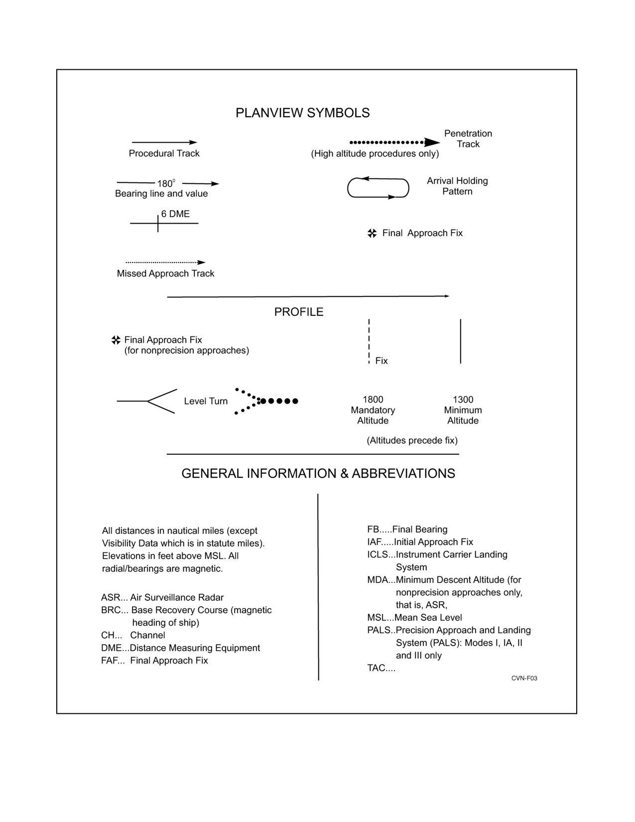
NAVAIR 00-80T-105
TACAN DME Fix
TACAN
TACAN)
TACAN
Figure 6-2. Legend Chart for Aircraft Carrier Instrument Approach Procedures
ORIGINAL
6-10

NAVAIR 00-80T-105
Figure 6-3. Approach Chart CV-1 TACAN (Jet and Turboprop)
6-11
ORIGINAL

NAVAIR 00-80T-105
Figure 6-4. Approach Chart CV-2 TACAN Overhead (Jet and Turboprop)
ORIGINAL
6-12
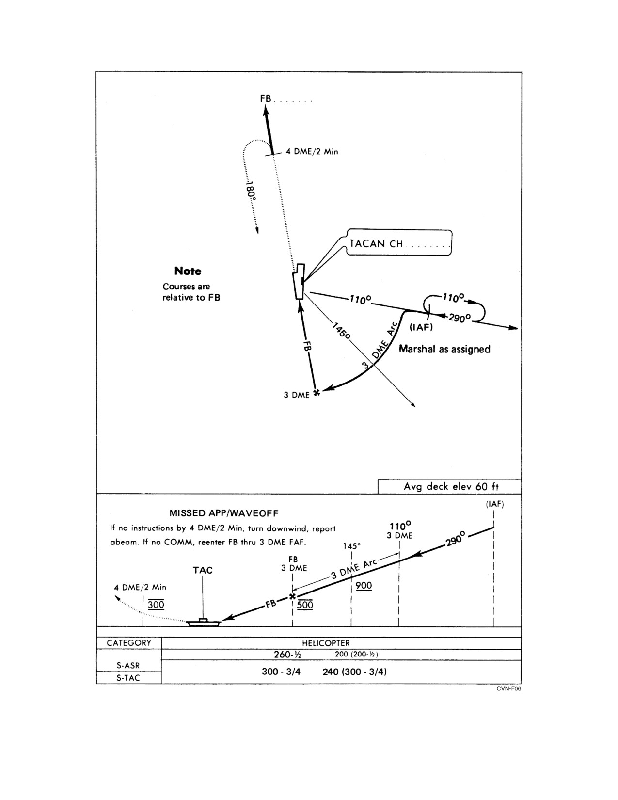
NAVAIR 00-80T-105
Figure 6-5. Approach Chart CV-3 TACAN (Helicopter)
6-13
ORIGINAL

NAVAIR 00-80T-105
AIRCRAFT
TYPE APPROACH
MINIMUMS
JET
NON-
600-1-1/4
PRECISION
ICLS
300-3/4
ICLS/ILM
200-1/2
W/SPN-42/46
MONITOR
MODE I
AS CERTIFIED
MODE IA, II, IIT, III
200-1/2
TURBOPROP
NON-
400-1
PRECISION
ICLS
300-3/4
ICLS/ILM
200-1/2
W/SPN-42/46
MONITOR
MODE II/IIT
200-1/2
III
HELICOPTER
NON-
300-3/4
PRECISION
MODE III
200-1/2
Note
• PALS Mode I qualified aircraft without an operating ILM may be certified to minimums of 200-foot ceiling
and 1/2-nm visibility.
• PALS Mode I qualified aircraft with an operating ILM display (ILM displayed on pilot’s HUD in single-
piloted aircraft or ILM displayed to pilot in command in single-piloted aircraft with side-by-side seating
occupied by pilot in command and an assisting NFO) may be certified to minimums less than 200-foot
ceiling and 1/2-nm visibility.
Figure 6-6. Approach Weather Minimums
6.4.7.4
PALS Mode I Approach (With AN/ARA-63/AN/ARN-138 Monitor)
Aircraft conducting PALS Mode I approaches with ceiling and visibility less than 200 feet and/or 1/2 mile must be
equipped with an operable independent monitor (AN/ARA-63/AN/ARN-138). For those qualified aircraft equipped
with AN/ARA-63/AN/ARN-138 ICLS flying CCA approaches to a AN/SPN-41 certified ship, the following
procedures shall be followed:
1. Jet aircraft shall pass through the 6-mile DME fix at 1,200-foot altitude, 150 KIAS, and in the landing
configuration and commence slowing to final approach speed. The pilot should engage aircraft APC and
AFCS. Normally between 4 to 8 miles, the pilot will receive via data link a landing check discrete signal to
indicate positive data-link communications between aircraft and ship.
ORIGINAL
6-14

NAVAIR 00-80T-105
2. The final controller will acquire the aircraft between 3.5 and 8 miles and the PALS ready/lock-on discrete light
will illuminate. At that time, the final controller shall report lock-on with range, verify needles, issue
instructions as necessary for the aircraft to intercept the centerline, and instruct the pilot to report “coupled.”
3. At lock-on, the pilot selects PALS display (agreement of aircraft needles and PALS display will verify PALS
is locked on correctly to the aircraft). For example: “201 lock-on, 5 miles. Say needles.” The pilot shall report
needle position. For example: “201, needles up and right.” The controller reports, “Concur report coupled.”
The controller shall not transmit commands until the pilot has reported
“coupled.”
Note
If aircraft is unable to couple or uncouples, continue approach as Mode II,
ICLS, Mode III.
4. The final controller shall report sending commands. The command control discrete light will illuminate,
indicating the PALS system is sending command signals via data link. The pilot shall acknowledge receiving
data-link commands by reporting “command control.” Thirty seconds coupled flight should be flown prior to
intercepting glidepath.
5. The final controller shall advise the pilot when “approaching tipover” (glidepath) and should issue range each
mile. At tipover, the pilot should switch to ILM, if available, to verify agreement of ILM and AN/SPN-42/46
displays. The ILM shall be used to monitor the approach to PALS Mode I minimums. ILM and AN/SPN-42/46
displays shall agree to within 2 to 3 needle widths until reaching PALS Mode I minimums.
6. The final controller shall advise the pilot at minimums unless the LSO has previously assumed responsibility.
The pilot shall respond with “ball” report and include the word “coupled.” For example: “301 Hornet ball, five
point three, coupled.” Expect ILM needle deviation errors inside one-quarter nm from touchdown. Use the
Fresnel lens as the primary monitor inside PALS Mode I minimums.
D PALS discrete lights shall be closely monitored throughout the approach
to ensure that PALS remains coupled and is working properly.
D The CCA Officer shall suspend Mode I approaches when PALS
Certification/Verification restrictions
(i.e., WOD limits, deck motion
parameters, etc.) are exceeded.
6.4.7.5
PALS Mode IA Approach (ILM Not Required)
Mode IA approaches are conducted the same as Mode I except the pilot shall uncouple at or prior to reaching approach
minimums and report “uncoupled.” If the pilot uncouples at “ball” call, he shall include the word “uncoupling” in
the ball report. For example: “201 uncoupling, hornet, ball, five point three, manual/auto.” When the pilot reports
uncoupling, the controller shall downgrade the PALS to Mode II.
6-15
ORIGINAL
NAVAIR 00-80T-105
6.4.7.6
PALS Mode II Approach (ILM Not Required)
1. Mode II approaches are conducted the same as Modes I/IA until receipt of PAL ready/lock-on discrete light.
At that time, the controller shall report lock-on with range, verify needle presentation, and issue instructions
as required. For example: “201, lock-on, 5 miles, say needles.” The pilot shall report needle position. For
example: “201, needles up and right.” The controller shall concur or downgrade the approach to ICLS or Mode
III and advise the pilot. For example: “201, concur” or “201, disregard needles, downgrade, fly Bullseye or
Mode III.” The controller shall monitor the approach, advise the pilot when approaching glidepath, and should
inform him of range each mile. The controller shall advise the pilot when at minimums unless the LSO has
previously assumed responsibility. The pilot shall respond with a ball report.
2. PALS Mode IIT approach is a training approach using needles instrument presentation (Mode II) as well as
Mode III information.
6.4.7.7
PALS Mode IID Approach (ILM Not Required)
For those qualified aircraft equipped with Mode IID (flight director) flying CCA approaches to a Mode IID certified
ship, the following procedures shall be followed:
1. Mode IID approaches are conducted the same as Modes I/IA/II until receipt of PALS ready/lock-on discrete
light. After receipt of PALS ready/lock-on discrete light, the final controller shall report lock-on with range,
verify needles, and issue instructions as necessary for the aircraft to intercept the centerline.
2. At lock-on, the pilot selects PALS display (agreement of aircraft needles and PALS display will verify PALS
is locked on correctly to the aircraft). For example, “101, needles up and right.” The controller shall concur
and report, “Concur, sending flight director”, or, “Disregard needles, downgrade Mode III.”
Note
If aircraft is unable to receive flight director data or if receipt of flight
director data is terminated, continue Mode II or Mode III.
3. When the controller enables the flight director mode, the flight director symbol is automatically displayed on
the aircraft HUD. The pilot shall acknowledge receiving the data-link signals by reporting, “Receiving flight
director.”
4. The final controller shall advise the pilot when approaching glidepath and should issue range with each mile.
The final controller shall advise the pilot at minimums unless the LSO has previously assumed responsibility.
The pilot shall respond with a ball report.
6.4.7.8
PALS Mode III Approach
Jet and turboprop aircraft shall pass through the 6-mile DME fix at 1,200 feet altitude, 150 KIAS, in the landing
configuration and commence slowing to final approach speed. The 1,200-foot altitude will be maintained at approach
speed until intercepting the glidepath (approximately 3 miles, dependent upon glideslope angle utilized) unless
otherwise directed.
Helicopters shall pass the 3-mile DME fix at 500 feet in a landing configuration and maintain 500 feet until
interception of the glidepath or until otherwise directed.
The controller shall provide glideslope, azimuth, and range information. Pilots may use the 400 foot-per-mile rule
to help schedule glideslope maintenance. The controller shall advise the pilot when at minimums unless the LSO has
previously assumed responsibility. The pilot shall respond with a ball report.
ORIGINAL
6-16
NAVAIR 00-80T-105
Note
Lock-on must be maintained until touchdown during all PALS approaches
to provide the LSO with essential course and glidepath information.
6.4.7.9
ICLS Approach
Jet and turboprop aircraft shall pass through the 6-mile DME fix at 1,200 feet altitude, 150 KIAS, in the landing
configuration and commence slowing to final approach speed. ILM information shall be used to intercept and fly
centerline and glideslope, and TACAN information shall be used for DME information until reaching ICLS
minimums. ILM information may be used to achieve lineup early in the approach.
6.4.7.10
Nonprecision Approach
When precision approach radar or suitable visual landing aids are not available, jet aircraft on final approach should
continue descent to 600 feet (400 feet for turboprop aircraft) after passing the 3-mile DME fix. The final controller
will provide sufficient information to the pilot for him to maintain an accurate azimuth and altitude until reaching
nonprecision minimums.
Note
Per NATOPS Instrument Flight Manual (NAVAIR 00-80T-112) the pilot
should establish a rate of descent which will ensure reaching the MDA at
or before the missed approach point.
6.4.8 Missed Approach/Waveoff/Bolter
Jet and turboprop aircraft shall climb straight ahead on the extended final bearing to 1,200 feet altitude and wait for
instructions from approach control.
Helicopters shall climb straight ahead on the extended final bearing to 300 feet altitude and await instructions from
approach control.
All waveoff/bolter pattern turns shall be level.
If no instructions are received prior to reaching 4 miles or 2 minutes ahead of the ship, the pilot will attempt to make
contact with the ship, giving identification and position. If instructions are not received, he will assume
communication failure and execute a turn downwind reporting downwind abeam. If radio contact is not reestablished,
he will proceed downwind and reenter as follows:
1. Fixed-wing aircraft commence turn to final at the 4 nm DME or 2 minutes past abeam position.
2. Helicopters reenter through the 3 nm DME fix or turn inbound 2 minutes past abeam.
3. PALS aircraft shall be alert for data-link displays.
6.4.9 Delta Procedures
In the event the deck becomes fouled or an excessive number of aircraft bolter or wave off, the CCA Officer shall
issue via marshal control a signal Delta. The signal Delta shall be accompanied by the number of minutes of delay
(even increments but never less than four) required to resume recovery operations (i.e., Delta 4, Delta 6, and so forth).
1. In marshal — Aircraft shall continue holding and await assignment of new EAT.
6-17
ORIGINAL

NAVAIR 00-80T-105
2. Commenced aircraft — Commenced aircraft above 7,000 feet shall level off at the next lower odd altitude and
hold on the inbound bearing at a range in nm equal to holding altitude in thousands of feet plus base distance
(angels + 15). The holding pattern shall be the same as the original marshal pattern. Aircrews shall report
established in holding with new altitude and await assignment of new EAT. Aircraft at or below 7,000 feet will
continue the approach.
Note
CV-2 aircraft that have descended from assigned marshal altitude shall
return to overhead holding at the next lower odd altitude. CV-2 aircraft that
have commenced but have not vacated their last assigned marshal altitude
shall return to overhead holding at that altitude.
3. Issuance of EATs — Marshal control shall issue new EATs as soon as possible. To preclude two aircraft having
the same EAT, new EATs shall be issued from the latest to the earliest (i.e., top of the holding pattern to the
bottom). Aircrews shall acknowledge receipt of the new EAT.
4. Lost communications — Aircraft in marshal shall commence approach at the last acknowledged EAT. Aircraft
between marshal and
7,000 feet that have established Delta holding and subsequently realize lost
communications prior to acknowledging new EAT shall commence approach immediately. All lost
communication aircraft shall squawk the appropriate Mode I (HEFOE) and III codes. Pilots shall take a 30_
cut to the right to intercept a track 10_ to the right of the inbound bearing and continue inbound to the ship.
Be alert for possible aircraft in Delta holding at lower altitudes.
6.4.10 Night EMCON Recovery
6.4.10.1
All Aircraft Except Helicopters
This type of recovery shall be employed when operating under EMCON conditions and the ceiling and visibility are
at least 3,000/5. Aircraft shall return to a prebriefed holding pattern and monitor marshal frequency. All aircraft will
have lights on bright and steady with anticollision lights on. When ready to recover aircraft, the CV will turn on the
lens and deck lights, flash the green cut light, and flash a white Aldis lamp. Aircraft will descend in accordance with
air wing doctrine to not lower than 600 feet, which will be maintained until the ball is in sight. After the last jet is
aboard, the tanker will be given a Charlie by a white Aldis lamp that he will acknowledge by turning off his
anticollision light as he descends.
6.4.10.2
Helicopters
Helicopters approaching the carrier for landing shall enter starboard holding. The pattern will have to be flown
visually by making estimates on the 45_ and the 110_ relative bearings. Caution must be exercised not to drift aft
of the 110_ relative bearing. Altitude, airspeed, and spacing restrictions remain the same as night/VMC (at least
3,000/5). Upon entering the pattern, the helicopter will turn navigation lights to flashing bright. After the last
fixed-wing aircraft has turned final or when given a green light or Charlie signal (see Figure 3-2 of Aircraft Signals
NATOPS Manual (NAVAIR 00-80T-113)), the helicopter leader shall accelerate to 90 knots and at the right-hand
abeam position turn to intercept the optical glideslope at 1 mile and 400 feet. At the 45_ position, the lead helicopter
will receive a green light from the tower if cleared for the approach. When cleared, he will then turn his navigation
lights to steady dim, leaving his tail position light on bright. If there is more than one helicopter airborne, they will
ORIGINAL
6-18
NAVAIR 00-80T-105
all perform the same procedures as they pass through each checkpoint. If, when passing through the 45_ position,
a red light is received (Delta), then that helicopter and all following will wave off to the right, reentering starboard
holding.
6.4.11 Communication or NAVAID Failure During Approach
6.4.11.1 Aircraft Alone
If navigational equipment is available, lone aircraft will continue approach. Pilot may utilize emergency survival
radio on guard (243.0) frequency if time and safe control of aircraft permit. If all communication and navigational
equipment is lost, the pilot will proceed as follows.
The pilot may elect to continue the approach by dead reckoning. Having made this decision, he will continue DR
until at least 2 minutes past his expected ramp time, then climb on final bearing heading to VMC, squawk
EMERGENCY, and conserve fuel. If below the overcast, the pilot may elect to fly a search pattern to locate the ship.
If the pilot elects to discontinue the approach, he will climb on final bearing heading to VMC and expeditiously join
up on the tanker or other available aircraft and conserve fuel. Depending upon weather at the divert field and fuel
state, the pilot may elect to proceed directly to the divert field after having climbed out on the final bearing heading.
Helicopters may continue descent to 300 feet, proceed by DR until 2 minutes past individual expected ramp time,
and then fly the appropriate triangular pattern for lost communications, squawk EMERGENCY, and conserve fuel.
PALS-equipped aircraft shall be alert for data-link displays. Mode II information shall be transmitted to suitably
equipped aircraft.
Aircraft equipped with an operating ARA-63/ARN-138 should conform to the NATOPS lost communication
procedures utilizing the ARA-63/ARN-138 and TACAN during the recovery phase to intercept the final approach
course and glideslope. Under conditions of intermittent or erroneous TACAN azimuth information, a 12-nm arc
should be flown at an altitude of 3,000 feet. Final bearing will be indicated by the centering of the ARA-63/ARN-138
azimuth needle. When approach to the final bearing is indicated, an immediate turn and landing transition should
be completed in the expected direction of the final approach course determined during the arc. Azimuth tracking on
the inbound ARA-63/ARN-138 radial to the glideslope (approximately 8 nm) and constant glideslope to ball
acquisition can be flown.
Extreme care shall be exercised by controllers and pilots using the above
procedure. The controller must ensure positive aircraft identification prior
to lock-on. The pilot shall cross-check his approach with other available
instruments (DME, altimeter, etc.).
Note
D The glideslope information of the ARA-63/ARN-138 should not be used
until within 20_ of the final bearing because geometric effects of the planar
SPN-41 elevation antenna cause erroneous elevation indications.
D An initial turn in the wrong direction upon intercept of the
ARA-63/ARN-138 final bearing will result in the glideslope indication
continuing to climb and inverse azimuth tracking.
6-19
ORIGINAL

NAVAIR 00-80T-105
6.4.11.2 Aircraft in Company
An aircraft with navigation and/or communication equipment inoperative in the company of an escort aircraft with
navigation and communication equipment in working order will be handled as a single aircraft in the recovery
procedure. The escort aircraft becomes the flight leader and will visually communicate with the distressed aircraft
in accordance with standard aircraft NATOPS procedures. The distressed aircraft will assume a position on the
starboard wing of the lead aircraft. Transition to landing configuration should be made clear of clouds either above
or below the overcast as desired. The controller shall be advised when this transition does/will occur, when the lead
aircraft has the OLS in sight, he will visually communicate a lead change and break off to the left. The distressed
aircraft will continue a visual approach to landing. The escort aircraft will parallel the final bearing course and
maintain a position so as to be easily acquired and be rejoined by the distressed aircraft in the event of a bolter or
waveoff. Unless otherwise directed, the escort aircraft will repeat the above procedures until the distressed aircraft
is recovered and then continue normal procedures for his own recovery. The SPN-42/46 radar should be locked onto
the lead aircraft. The PALS final controller should instruct lead aircraft “beacon on,” wingman “beacon off,” and then
select “beacon lock only” on the SPN-42/SPN-46 console.
If the address of the escorted aircraft is inserted in the PALS, the escorted
aircraft will receive needle information. When the lead aircraft breaks away
on OLS acquisition, this may give the escorted aircraft an erroneous “fly
down, fly right” presentation on the needles. The displayed error may
become progressively larger as both aircraft close on the ship regardless of
the approach actually being flown by the escorted aircraft.
6.4.11.3 Failure of Carrier Navigation Aids/CATCC Radars Prior to Approach
Individual ships should develop special procedures to recover airborne aircraft in the event of a casualty to shipboard
air traffic control equipment. Selection of special/alternate approach procedures will be dictated by the availability
of suitable navigational equipment aboard escort ships and/or embarked aircraft. Should the use of assist ship
navigation equipment or utilization of airborne radar and control become necessary, approach minimums, separation
between aircraft, and size of the recovery will be adjusted so as to ensure safety of recovery operations.
6.4.12 Radar Handoff Procedures
Positive radar identification shall be accomplished by the receiving agency prior to transfer of control. Control will
be transferred only after the receiving agency has notified the transferring agency that positive radar contact has been
established.
6.4.13 Voice Communication Procedures
6.4.13.1
Compulsory Arrival, Marshal, and Approach Voice Reports
1. Entrance into carrier control area — Information required from flight leader (see paragraph 6.1)
2. Receipt of:
a. Marshal instructions
b. Type recovery
ORIGINAL
6-20
NAVAIR 00-80T-105
c. EAT or Charlie time
d. Altimeter setting
3.
Entering holding/marshal with altitude, fuel state, and hung/unexpended ordnance (if any)
4.
Altitude changes
5.
Commencing approach, with fuel state, altimeter setting
6.
Frequency changes
7.
Platform (jet/turboprop aircraft)
8.
Ten miles (jet/turboprop aircraft)
9.
“Coupled/needles” as appropriate and “command control” if Mode I/IA approach
10.
Three miles (helicopters)
11.
Breaking away (section approaches only)
12.
Ball call report — (side number, aircraft type, ball or Clara/Clara lineup, fuel state, hung/unexpended
ordnance, coupled/uncoupling (if applicable), automatic/manual)
13.
Waving off
14.
Abeam, with fuel state after bolter/waveoff.
6.4.13.2
Phraseology
Standard ATC and precision instrument approach phraseology shall be used with the following exceptions:
1. Fuel state reports (thousands of pounds; for example, “3.5”)
2. Altitude (angels; for example, “1.2”)
3. Heading changes on Case III final approach after lock-on or final radar contact (normally soft headings; for
example, “301, right five”).
6.5
RECOVERING FIXED-WING AIRCRAFT
6.5.1 Preparation for Recovery
Preoperational checks of the arresting gear, optical landing aids, and associated equipment are ordinarily completed
before the beginning of air operations; therefore, preparation for recovery generally consists of nothing more than
manning the necessary stations. Whenever fixed-wing aircraft are airborne, all arresting gear equipment shall be
maintained in a ready status unless the commanding officer has granted permission to place specific items of
equipment out of commission for maintenance or other reasons.
Fifteen minutes before each scheduled recovery or immediately upon hearing the word passed to prepare to recover
aircraft, personnel will man stations and take the following preparatory actions.
6-21
ORIGINAL
NAVAIR 00-80T-105
The air officer shall perform the following:
1. Confirm the recovery time with CATCC and the bridge.
2. Obtain the expected BRC.
3. Provide CATCC the break time for Case II recoveries or ramp time for Case III recoveries.
4. Monitor/update fuel status of returning aircraft, information on hung or unexpended ordnance, aircraft
emergencies, if any, and the current altimeter setting.
5. Confirm with the bridge that the fantail and adjacent sponson(s) are secured during recovery of fixed-wing
aircraft.
The ILARTS and PALS radar operators shall ensure equipment is turned on and operating.
The PriFly lens operator shall receive permission from the air officer prior to turning on lens.
The recovery equipment controller in PriFly shall perform the following:
1. Ensure all arresting gear engines, the arresting gear deck-edge station, ILARTS room, and lens room are
manned and ready to recover aircraft.
2. Report to the air officer when all stations are manned, giving the existing arresting gear engine and lens
settings.
The arresting gear officer shall perform the following:
1. Inspect the landing area for loose gear.
2. Ensure all after deck-edge antennas are positioned as required.
3. Check the condition of crossdeck pendants, barrel fittings and wire supports, and ensure retractable sheaves
are in the raised position.
4. Ensure all aircraft and mobile equipment parked on the flight deck are inside the safe-parking line.
5. Ensure hook runners and the deck-edge operator are on station.
6. Ensure the ready barricade, including deck ramps, is in a ready status, with a clear route to the area and a tractor
with driver is standing by.
7. Ensure waist catapult slot buttons are installed in accordance with current bulletins and ensure the deck status
light is operating.
8. Notify PriFly when the deck is ready.
The flight deck officer shall perform the following:
1. Ensure the mobile crane, a forklift, and a tractor are warmed up and that drivers are standing by. Also ensure
operationally ready mobile firefighting equipment is manned and that all have clear access to the flight deck.
2. Ensure the crash crew is on station and that directors and plane handlers in sufficient number are standing by.
3. Ensure the flight deck area is clear of all unnecessary personnel.
4. Ensure the flight deck is clear of unnecessary equipment and that all deck hatches in the landing area are closed
and properly secured prior to signaling a ready deck forward.
ORIGINAL
6-22
NAVAIR 00-80T-105
The LSO shall perform the following:
1. Conduct a two-way radio check and sound- powered phone checks on appropriate circuits.
2. Check the landing area lights and lens for proper brilliance when turned on and check the cut and waveoff lights
for proper operation.
3. Ensure the following distress equipment is available at the LSO platform:
a. Battery-powered marker
b. Life preserver ring
c. Very pistol
d. Search and rescue sonobuoy
e. Aldis lamp (night operations only).
The catapult officer shall ensure the following:
1. Catapult shuttles are properly positioned and shuttle cover installed on catapult 3.
2. Track slot seals are in place on bow catapults (except during CARQUALs).
3. Catapult deck gear is clear of landing area.
4. For ships so equipped, waist ICCS is fully lowered.
The weapons officer shall ensure the following:
1. An EOD representative shall be stationed in flight deck control during all operations when aircraft are carrying
weapons. Unless assistance is required, EOD personnel should not normally be exposed to the flight deck
during launches or recoveries.
2. The EOD officer, Air Gunner, and air wing weapons officer are equipped with an SRC-22 (or equivalent)
communication set during launch and recovery operations.
6.5.2 Flight Deck Procedures
For detailed flight deck procedures, refer to CV Flight/Hangar Deck NATOPS Manual (NAVAIR 00-80T-120).
6.5.3 Special Safety Precautions
Observe the following safety precautions.
1. While aircraft are being recovered, no personnel other than those required by this instruction shall be in the
catwalks, on the flight deck, or in the arresting gear engine rooms or ILARTS/lens room without the express
permission of the air officer.
2. The deck will be considered foul any time unauthorized personnel are in or around aircraft parked adjacent
to the landing area.
3. Personnel shall not stand in or otherwise block entrances to the island structure or exits leading off the catwalks.
6-23
ORIGINAL
NAVAIR 00-80T-105
4. Personnel shall not sit on missile equipment, chocks, deck-edge coaming, or any other object during flight
quarters or while aircraft is turning on the flight deck. Personnel should not turn their backs on aircraft landing
or taxiing out of the gear.
5. In taxiing aircraft out of the gear, directors must be aware of the activities of the hook runner, tillerbar man,
and wing riders.
6. All taxi signals shall be answered promptly and accurately unless the pilot considers that a dangerous situation
exists or is developing, in which case he shall stop immediately.
7. If a pilot loses sight of his director, he shall stop immediately. The director shall exercise care to remain in plain
view of the pilot at all times.
8. No director shall give signals to a pilot who is being controlled by another director except in an attempt to avert
an accident.
9. Personnel having reason to suspect the readiness or condition of any arresting gear engine, crossdeck pendant,
or associated equipment shall immediately cause the deck to be fouled by informing the arresting gear officer,
deck-edge operator, and the recovery equipment controller in PriFly.
If the arresting gear crew is required to enter the landing area during aircraft
recovery, a safety person shall be stationed forward of that crew, facing aft,
to ensure the arresting gear crew is warned of approaching aircraft in time
for them to safely exit the landing area.
10. If during recovery operations any part of the aircraft affecting safe recovery strikes the ramp, aircraft, or other
equipment on deck or ship’s structure other than normal flight deck protrusions (crossdeck pendants, flight
deck light covers, ILARTS heads, or waist catapult ramps) and the aircraft subsequently bolters, no further
effort shall be made to effect a normal carrier arrestment.
11. PALS radar beacon-equipped aircraft parked or taxiing aft of the island shall have the beacon switch in off or
standby position during recovery operations. Aircraft preparing for launch shall delay PALS beacon self-test
until forward of the island or airborne.
12. Pyrotechnic devices shall not be used in marking aircraft accident sites to preclude igniting aviation fuel.
To minimize the possibility of an aircraft landing on a foul deck, the following procedures are mandatory.
1. The lens (and at night, the landing area lights) shall never be turned on without the express permission of the
air officer.
2. Except for the purpose of conducting tests, neither the lens nor the landing area lights shall be turned on until
the controlling LSO establishes positive communications with the air officer.
3. The waveoff lights shall be continuously activated anytime the lens or landing area lights are turned on and
the LSO is not on the platform.
4. Aircraft shall be permitted to conduct practice CCA approaches, including PALS approaches. When the OLS
is on and deck lights (night only) are on, PriFly and the LSO platform shall be manned by qualified personnel.
Both stations will have communications with the aircraft; assigned minimums shall be no lower than 200 feet
and one-half mile. With OLS and deck lights (night only) off, the LSO platform need not be manned. CCA
ORIGINAL
6-24
NAVAIR 00-80T-105
shall not assign minimums lower than 500 feet and 1 mile. In all cases, CCA will issue, “This is a practice
approach to a low approach only. Upon reaching (minimums), execute waveoff.”
5. To avoid unnecessary delay in recovering the first aircraft, the lens and/or landing area lights may sometimes
be turned on a short time before the ship is completely ready to commence recoveries. When this is done, the
LSO shall wave off approaching aircraft at a distance of one-half mile or greater if he has not received the “clear
deck” signal.
6. During instrument recoveries, PriFly will keep CATCC advised as to the status of the deck and provide the
estimated time the deck will be clear. CATCC shall keep PriFly advised as to the type and position of the nearest
aircraft.
7. Combat and CATCC must keep PriFly informed of any aircraft known or suspected to have radio failure.
8. After calling “ball,” if no verbal/visual acknowledgment of positive control by the LSO is received, the pilot
shall execute his own waveoff early enough to clear the landing area by 100 feet above flight deck level.
The deck is foul when any of the following conditions exist:
1. The red rotating beacon is on.
2. Personnel, aircraft, support equipment, or loose gear are in the landing area.
3. Arresting gear engines are not properly set and in battery.
4. There is a known or suspected malfunction of recovery equipment.
5. After each touch and go, arrestment, bolter, or waveoff.
Note
During night operations when the deck is open, but momentarily foul, the
landing deck lights will remain on and foul deck waveoff will be controlled
by the LSO.
During night operations, green wands shall be used only by those air department personnel authorized to launch
aircraft or signal a clear deck.
6.5.4 Control of the Landing Pattern (VMC)
The air officer is charged with the overall control of the VMC landing pattern (Figure 6-1) and is assisted by the LSO.
Specific responsibilities are assigned as follows.
6.5.4.1
Air Officer
1. Provide pilot with sufficient information to ensure that aircraft are established in the landing pattern in time
to meet the expected Charlie time.
2. Assign or revise the landing order as necessary.
3. Regulate the number of aircraft in the landing pattern to ensure a steady flow of traffic while preventing the
pattern from becoming extended or overcrowded.
4. Monitor the landing interval.
5. Whenever possible, maintain visual contact with all aircraft in the Charlie pattern.
6. Maintain an accurate count of the number of aircraft to be recovered and inform the bridge when only two
remain.
6-25
ORIGINAL
NAVAIR 00-80T-105
7. Monitor the upwind pattern, being particularly alert to warn pilots of aircraft boltering or waving off of their
proximity to aircraft launching or breaking.
8. Maintain visual contact with aircraft that have radio failure and instruct the LSO with regard to visual signals
to be given.
9. Inform the LSO of any unusual condition(s) affecting the normal recovery of aircraft.
6.5.4.2
LSO (Under the Supervision of the Air Officer)
1. Control all fixed-wing aircraft approaches after the 180_ position.
2. Ensure that approaching aircraft are properly configured.
3. Monitor the operation of the OLS and cross check the approach radar/ICLS glidepath angle.
4. Instruct and supervise the LSO talker and hook spotter.
5. Assist in controlling aircraft that have radio failure by flashing the cut or waveoff lights in accordance with
signals delineated in Figure 6-11.
6. Whever possible, maintain visual contact with all aircraft in the Charlie pattern.
7. Inform the air officer of any unusual conditions affecting the safe recovery of aircraft.
6.6
RECOVERING HELICOPTERS
6.6.1 Recovery Procedures
When recovering after night plane guard duties, helicopters should be provided positioning information by CATCC
in order to expeditiously intercept the glideslope and effect a landing following recovery of the last fixed−wing
aircraft. When a flight of helicopters is being recovered under VMC, the leader of the flight should plan to be at the
ramp within a minimum safe interval after the last fixed−wing aircraft has landed. The helicopter which is the farthest
advanced on the inbound radial and has not turned to parallel the ship’s course will be considered No. 1 in the landing
pattern and should expeditiously effect a landing following recovery of the last fixed−wing aircraft. The helicopter
cleared No. 1 to land should be assigned a landing spot farthest forward into the wind. Subsequent helicopters should
be cleared to land in sequence behind the No. 1 helicopter. In the event the last fixed−wing aircraft waves off, all
helicopters shall reposition in the pattern (with CATCC assistance as required) to take interval on that last fixed−wing
aircraft. Prior to issuing landing clearance, the air officer shall ensure the helicopter may land within the relative wind
envelope prescribed in the respective aircraft NATOPS flight manual, and the tower shall transmit relative wind
direction, speed, and landing spot(s). For landings not oriented to the angle or axial centerline (day VMC only), the
air officer will ensure an adequate waveoff path is available to the helicopter.
Because of the severe rotorwash and wing-tip vortices produced by CH-53E,
MH-53E and V-22 aircraft, land/launch operations should not be conducted
upwind of other aircraft or any unsecured area. Because of this severe hazard,
consideration should be given to conducting CH-53E, MH-53E and V-22
operations from after-deck spots only.
ORIGINAL
6-26

NAVAIR 00-80T-105
Note
D Rotating beacon light signals for helicopter operations are contained in the
Aircraft Signals NATOPS Manual (NAVAIR 00-80T-113).
D Army helicopters are not equipped with an automatic blade fold/spread
system. Time for manually folding and spreading main rotor blades should
be taken into account for tactical planning during shipboard operations.
D Certain Army and Air Force helicopters are not equipped with a rotor brake.
Extended rotor coast down times can be expected. These times can vary
with relative wind speed and direction, and can exceed 8 minutes in winds
as light as 20 knots. The ship shall be ready to provide optimum winds for
the windmilling stop of the rotor system.
During Case III recoveries, the approach shall be flown as directed by CATCC until the pilot acquires visual contact
with the optical landing aids, at which time the pilot shall “call the ball.” Control will then be assumed by the air
officer, who shall issue final landing clearance. In the event of a waveoff, the pilot shall parallel the final bearing
course and report to CATCC for control. At night, navigation lights shall be steady bright and anticollision lights on
until established on the final bearing, at which time the position lights shall be placed on dim and steady.
The forward anticollision light shall be turned off when the meatball is in sight.
When the word is passed to stand by to land helicopters, the LSE shall take a position clearly visible to the pilot. The
tower will obtain a “gear down” report from the pilot before issuing final landing clearance. As the helicopter
approaches, the LSE shall ensure the landing gear is down, the rotating beacon that controls his area of the flight deck
is green or amber, as appropriate, and that the landing area is clear of personnel, equipment, and loose gear.
Except in unusual circumstances, helicopters shall be landed only on marked spots visible to the pilot during the final
approach.
Except for the “waveoff” and “hold” signals, the LSE signals will be accepted as advisory and the pilot has full
responsibility for the proper and safe operation of the aircraft. At night when two or more helicopters are landing,
the navigation light shall remain STEADY/DIM and the tail anticollision light shall remain ON until touchdown.
After landing and before disengagement, chocks will be placed on the main wheels and the initial aircraft tiedowns
will be attached by the deck crew. A hold signal will be given by the LSE while tiedowns are being attached to indicate
that an unsafe takeoff condition exists. Navigation lights shall be switched to FLASHING DIM (day: FLASHING
BRIGHT) until the rotors have been disengaged and are fully stopped. The LSE will then signal for the aircraft lights
to be turned OFF. When helicopters are recovered immediately ahead of fixed-wing aircraft, pilots shall shut down
and disengage as expeditiously as feasible. They shall remain in their aircraft until towed clear of the fixed-wing
landing area. An amber or red light will be ON whenever rotors are engaged on deck.
6.6.2 NVD Equipment Aided Approaches
Crews aided with NVD may make a visual approach to a spot rather than a Carrier Controlled Approach (CCA)
provided such an approach is coordinated with Air Officer/PriFly, are not IMC, and have sufficient illumination/
visibility.
Night Vision Device (NVD) Centerline Visual Approach. During VMC and using NVDs, the HAC may accept a
visual approach to the fantail and proceed along the centerline for landing on the designated spot. After the last fixed
wing aircraft on final is identified by the Air Boss/CATCC, the helicopter will take interval and land visually.
Night Vision Device (NVD) Slide-in Visual Approach. At the HAC’s discretion, the helicopter may slide in to a
landing on the designated spot. Visual contact with the ship and NVD usage is required.
6-27
ORIGINAL

NAVAIR 00-80T-105
6.6.3 Recommended Deck Lighting Configuration for Helicopter NVD Aided Takeoff and Landing
See paragraph 5.7.3 for the recommended deck lighting configuration.
6.6.4 Special Safety Precautions
The following precautions shall be observed when recovering helicopters.
Inverted “T” helicopter and tiltrotor aircraft spots 2 through 6 do not
provide adequate clearance for all combinations of helicopters. If any spot
1 through 6 is occupied by an H−46, H−47, H−53, or V-22, the spots
immediately forward and aft shall remain vacant.
1. Except in case of emergency, pilots shall not stop engines or fold rotor blades without proper clearance from
the LSE.
2. If ship roll (heel) is greater than 4°, helicopters should not be recovered while the ship is in a turn.
3. Personnel required to be in the area of helicopters disengaging rotors shall stand next to the fuselage or well
outside the rotor arc.
4. A helicopter shall not be flown over another aircraft when landing.
CAUTION
The combination of relative winds and rotor downwash when launching or
landing a helicopter immediately adjacent to a spot occupied by a
helicopter engaging/disengaging rotors, or occupied by a shutdown
helicopter not folded or secured by rotor blade tiedowns, may cause rotor
system damage to the engaging/disengaging or shutdown helicopter.
5.
Helicopters shall never be towed or pushed while rotors are engaged.
6.
The waveoff and hold signals are mandatory and shall be executed immediately.
7.
Case III unaided helicopter recoveries shall be conducted to the angled deck, from astern, utilizing the OLS,
with the wind oriented to the centerline of the angle deck, and within the parameters set forth in the respective
aircraft NATOPS flight manual. During night VMC recoveries on CVs equipped with operating white
floodlights and when the after portion of the flight deck is not clear, helicopters may make an approach utilizing
the OLS and centerline of the angle deck. Upon approaching the fantail and when the deck and LSE have been
visually acquired, the helicopter shall then slide over, fly up the port side to the landing spot, and slide into
a landing.
8.
Helicopters shall not cross within 5 miles of a ship’s bow and within 3 miles of a ship’s stern without specific
approval of the air officer. A vertical replenishment helicopter may request and be granted continuous use of
an established flightpath.
ORIGINAL
6-28

NAVAIR 00-80T-105
9. The air officer or his representative shall pass over the 5 MC, “Stand well clear of helo number — while
engaging/disengaging rotors.”
Inboard mounted external fuel tanks or stores on Army UH-60 Aircraft
significantly impede access to the main wheels, exposing flight deck
personnel to risk of injury in the event of inadvertent jettison or aircraft
movement while chocking. Consideration should be given to safing the
external stores jettison circuit prior to chocking, balanced with the need to
expeditiously chock and chain the aircraft to prevent aircraft movement
under severe deck motion conditions.
10. Spot 2 starboard approaches and departures are prohibited.
11. Left seat slide-in visual approach to spot 2 is not recommended.
12. Left seat slide-in visual approach to spot 3 is prohibited.
Left seat helicopter recoveries to spots 4, 5, and 6 while there is a turning
helicopter on next forward spot represents an increased risk to the LSE. The
LSE should be positioned inboard of the catapult four safe parking line in
the same general location as right seat recoveries.
13. Cross cockpit recoveries forward of an occupied spot are not recommended.
6.7
SPECIAL PROCEDURES FOR CARRIER QUALIFICATION LANDING
6.7.1 Fixed-Wing Aircraft
The number of aircraft in the Case I or II pattern should be limited to four and shall not exceed six.
Maintaining a proper and uniform interval is very important in the CARQUAL pattern. The air operations officer
and the air officer shall make appropriate recommendations. Jet/turboprop aircraft night CARQUALs shall be under
CCA control. Advisory control may be specified by the ship’s commanding officer when weather permits.
The air officer must be acutely aware of the responsibility to ensure the
initial separation between bolter/waveoff and departing aircraft during
CARQUAL and cat-trap-cat evolutions.
6-29
ORIGINAL

NAVAIR 00-80T-105
CATCC’s restricted radar coverage (blindspot) ahead of the ship requires
aircrew to exercise good lookout doctrine and radio discipline upon
departure.
During night CARQUALs, CCA shall utilize a single frequency to control all aircraft in the CARQUAL pattern.
Anytime CARQUAL or refresher landings are being conducted, a senior representative of each squadron involved
should be present in the tower. During IMC and night operations, his station will be in air operations. He must be
well qualified in the aircraft and prepared to advise the air officer in the event of an emergency.
It is the responsibility of the air operations officer to keep the air officer accurately apprised of the number of landings
required for each aircraft. Air operations/ CATCC will maintain a status board that will show landings required,
landings completed, and location of each aircraft (in Delta, in the Charlie pattern, or on the deck).
The air operations officer is responsible for providing the air officer with accurate bingo/divert data. Before
commencing and/or during CARQUALs, he shall compute the distance and bearing to the bingo/divert field and the
fuel required for the model aircraft involved. Bingo/divert data will be broadcast on the recovery frequency by PriFly
or CCA as appropriate.
The decision to divert aircraft will be made by the commanding officer or his designated representative. The air
operations officer and the air officer shall make appropriate recommendations during IMC/night and VMC
operations, respectively. In addition, the LSO will make timely divert recommendations to the air officer based on
unsatisfactory pilot performance or unsatisfactory CARQUAL conditions around the ship. It is the pilot’s
responsibility to inform the tower if he reaches bingo fuel state and has not been ordered to divert.
Changing pilots when an aircraft is on the flight deck with engine(s) running is an inherently dangerous practice
requiring extreme care. When a change is made, the aircraft shall be chocked and have at least the initial tiedowns
attached. Pilots shall not leave/switch their seats until given the “tiedowns in place” signal by the aircraft director.
Note
It is the pilot’s responsibility to inform the tower when reaching holddown
fuel state after trapping and the aircraft has not been taxied to a refueling
spot.
6.7.2 Helicopters
When feasible, two landing spots will be utilized for CARQUAL landings. The pattern shall be a left-hand racetrack
on the port side of the ship. Pattern spacing shall be adjusted to permit one aircraft to be launched prior to another
being landed. When the pilot acquires the meatball, he shall report his side number, “ball,” and “gear down.”
Night CARQUALs shall be under CCA control. Advisory control may be specified by the ship’s commanding officer
when weather permits.
The pilot in the right seat shall be in control of the aircraft unless the tower is informed to the contrary. When changing
pilots, the aircraft will be chocked and have initial tiedowns attached.
ORIGINAL
6-30
NAVAIR 00-80T-105
6.8
EMERGENCY LANDING
6.8.1 Fixed-Wing Aircraft
At first indication of a possible emergency landing, the air officer will pass the word “stand by to make a ready deck.”
At this time, arresting gear and Crash Salvage personnel, ILARTS, and lens operators will immediately man their
stations. It is the responsibility of PriFly to contact the LSO, who will proceed to the platform. The squadron duty
officer will be notified. Tractors will be attached to all aircraft parked in the landing area, tiedowns will be removed
when directed by the plane directors, and directors and chock men will stand by. A helicopter should be manned and
started unless an airborne helicopter is available for plane guard. If the emergency condition requires a straight-in
approach or a straight-in approach is contemplated, the SPN-41 shall immediately be activated without pilot request.
When it has been determined that an emergency landing will be made, the Air Officer will pass the word, “Make a
ready deck,” at which time the landing area will be cleared as expeditiously as safety permits. Personnel concerned
will stand by to rig the barricade if called for. The air officer shall pass an expected Charlie time to the distressed
aircraft.
Pilots of aircraft returning to the ship for an emergency landing shall not shift from the control frequency to tower
frequency until directed to do so unless radio contact has been lost on the control frequency. Normally, the tower and
LSO will shift to the control frequency, thereby avoiding the necessity of a frequency change by the pilot. In no case
will the pilot of an aircraft in distress leave an assigned frequency without broadcasting the frequency to which he
is shifting.
As the ship is being prepared for the landing of aircraft, the air officer will pass as much pertinent information as
possible to the flight deck, bridge, LSO, and CATCC. The air officer shall determine the amount and type of
firefighting equipment to be broken out and direct the deployment of personnel, depending upon the nature and
seriousness of the emergency.
6.8.2 Helicopters
As much deck space as possible will be made available for emergency helicopter landings. If time permits, the senior
helicopter squadron or unit officer on board should take station in the tower or in CATCC, and the air officer should
determine the optimum relative wind and request the bridge to maneuver the ship as necessary. In clearing a helicopter
for an emergency landing, PriFly will ordinarily designate an area of the flight deck rather than a specific landing
spot. Once the aircraft is on final approach, it is imperative that the ship hold a steady course.
During an emergency landing, the LSE, if immediately available, shall stand at the upwind edge of the designated landing
area. The LSE signals are advisory in nature, except for the waveoff and hold signals, which are mandatory. The LSE
shall give a waveoff only in case of a foul deck or if instructed by the tower to do so.
6.9
EMERGENCY SIGNALS
6.9.1 Visual Signals to Ship From Aircraft With Radio Failure
Figures 6-7 and 6-8 provide visual signals to be used in the event of radio failure. Aircraft configuration is the primary
daytime indicator of the pilot’s desires or intentions. At night, aircraft lighting configuration is the primary indicator
of the pilot’s desires or intentions.
6.9.2 Visual Signals to Aircraft From Ship Under EMCON or Lost Communication Conditions
Figure 6-9 provides visual signals for giving commands or advisories to aircraft when the ship has lost its
communication capability or is under EMCON conditions.
6-31
ORIGINAL
NAVAIR 00-80T-105
6.9.3 Carrier Pattern Emergencies
The LSO will make appropriate recommendations to the air officer or pilot as indicated in Figure 6-10.
6.9.4 Day Communication Emergencies
Figure 6-11 describes appropriate action for day communication emergencies.
6.9.5 Night Communication Emergencies
Figure 6-12 describes appropriate action for night communication emergencies.
6.10
TANKER OPERATIONS
Tankers assigned duties in support of the recovery of aircraft shall use the following procedures:
1. Only those tankers that have a known good store and sufficient fuel to meet receiver fuel requirements shall
display the flashing green light.
2. For optimum utilization of tankers, single-cycle operation is recommended.
3. A specific existing agency (i.e., departure control) shall be designated tanker control with the responsibility
to monitor:
a. Tanker give-away fuel status
b. Tanker location
c. Location and fuel requirements of the low state aircraft
d. Coordination of the tanker and receiver rendezvous.
6.10.1 Recovery Tanker Procedures
6.10.1.1
CASE I/II
After launch, the oncoming recovery tanker shall switch to departure control for assignment. All tanker packages
should be checked as soon as possible after launch. When it has been determined that the new tanker store is
operational, departure control should be advised immediately. The recovery tanker shall maintain a rendezvous circle
oriented on the CV (Figure 6-13). The rendezvous circle shall contain four reference points. Minimum pattern altitude
shall be 1,500 feet. This pattern is a left-hand circle within 5 nm of the CV during launch and recovery operations.
When the last jet is aboard, the tanker shall climb to prebriefed altitude and switch to assigned frequency for
control.
ORIGINAL
6-32
NAVAIR 00-80T-105
PILOT’S DESIRES OR INTENTIONS
VISUAL SIGNAL
1. I desire immediate landing.
Fly up the port side of the ship, low and close aboard,
rocking wings, in a landing configuration with hook
down. Navigation lights bright and steady with
anticollision light on. If turning final in VFR pattern or
approaching final on a CCA, momentarily turn on the
taxi light, if available.
2. I desire to land but can wait for the next recovery.
Fly up the port side with the landing gear up, hook
down, navigation lights bright and steady, and anticolli-
sion light off while abeam the ship.
3. I am proceeding to the bingo field.
Fly up the port side of the ship, rocking wings, with
landing gear and hook up, navigation lights bright and
steady, and anticollision light on. If fuel state and
nature of the emergency permit, continue making
passes until joined by a wingman. Upon reaching
bingo fuel state, proceed alone, setting IFF/SIF to
emergency when departing.
Note
1.
The requirement for gear down and rocking wings as the signal for an immediate landing is not required
when considered unsafe by the pilot due to the nature of the emergency; for example, loss of an engine in
multiengine aircraft.
2.
At night, aircraft flying close aboard the port side of the ship without lights are considered to have an
emergency requiring immediate landing.
Figure 6-7. Emergency Signals to Ship From Fixed-Wing Aircraft With Radio Failure
PILOT’S DESIRES OR INTENTIONS
VISUAL SIGNAL
1. I require immediate landing.
Fly close aboard starboard quarter, remaining clear of
other traffic, with gear down and floodlights/landing
light on. With complete electrical failure, fire a red flare
to seaward.
2. I desire to land but can wait for the next recovery.
Fly by or hover on the starboard side of the ship, low
and close aboard, with navigation lights bright and
flashing and anticollision light on.
Figure 6-8. Emergency Signals to Ship From Helicopters With Radio Failure
6-33
ORIGINAL
NAVAIR 00-80T-105
SIGNAL
COMMAND/ADVISORY
OLS
** ALDIS LAMP
FLASHING LIGHT
1. *BINGO—Proceed to alternate
Flashing cut and
Flashing red light.
M, M
landing field.
waveoff lights.
——,——
2. Add power—(Jets and turbo
Flash, cut lights.
N/A
N/A
props only).
3. CHARLIE—Cleared to land
N/A
Steady green light.***
C
aboard.
—D—D
4. DELTA—Delay in landing.
Flashing landing area
Steady red light.
D
Enter DELTA pattern and
lights.
—DD
maintain visual contact with
the ship.
5. Closed deck. Do not land.
Landing area lights off
N/A
N/A
(night only).
6. Do not land. Ditch or bail
N/A
Z
Z
out/eject in the vicinity of the
——DD
——DD
ship.
7. LSO has control of the aircraft
Steady (3 sec), cut
N/A
N/A
on final approach at approxi-
lights.
mately 1-1/2 miles.
8. Lower hook.
N/A
H
H
DDDD
DDDD
9. Lower wheels.
N/A
W
W
D——
D——
10. Lower flaps.
N/A
F
F
DD—D
DD—D
11. Jettison disposable fuel tank.
N/A
G
G
——D
——D
12. Jettison ordnance.
N/A
Q
Q
——D—
——D—
* Signal is given only when ordered by the Air Officer.
** Aldis lamps may be located in the tower, or on the signal bridge.
*** Helicopters will normally receive this signal from the rotating beacon or Aldis lamp on the starboard side
of the island.
Extra care must be exercised in identifying the correct light and
location of signal. Misinterpretation of the lighting signals from
other sources can occur. Such sources are rotating beacons (aft,
port, forward sides of island), or deck status lights (located at
LSO platform and near portside midships catwalk).
Figure 6-9. Visual Signals to Aircraft From Ship Under EMCON or Lost Communications
ORIGINAL
6-34

NAVAIR 00-80T-105
EMERGENCY
CARQUALS
DEPLOYED/REFRESHER
1.
Landing aids malfunc-
Discontinue landings.
Rig MOVLAS and continue recovery with radio
tion, under steady deck
as backup.
conditions, due to
improper stabilization.
2.
Complete landing aids
Discontinue landings.
If available, consider the use of an emergency
failure/damage.
field. If none is available and aircraft fuel state
does not permit delay:
1.
Establish positive radio contact with each
aircraft when commencing approach.
2.
Use radio talk-down as primary control.
3.
Have flare gun ready for instantaneous
use.
3.
Partial failure or damage
Discontinue landings.
Rig MOVLAS and continue recovery, with
of OLS, datum lights
radio as backup.
operative.
4.
Waveoff lights
Discontinue landings.
Continue landings with radio as primary means
inoperative.
of waveoff. Have flare gun ready for instanta-
neous use as a backup.
5.
Suspected malfunction,
Discontinue landings until a
Rig MOVLAS and continue recovery with radio
when consecutive
thorough check of OLS set-
as backup. A complete check of the OLS set-
approaches result in
tings and monitoring equip-
tings and monitoring equipment will be made
below glidepath
ment is accomplished.
upon completion of recovery.
conditions.
6.
Aircraft at night, no
Aircraft without an approach
Same as for CARQUALs.
approach light.
light shall be waved off for
visual check of the landing
gear and hook.*
7.
Any part of the aircraft
Do not attempt normal
Same as for CARQUALs.
striking the ramp or
arrestment.
ship’s structure other
than the normal flight
deck protrusions (cross-
deck pendant, flight
deck light covers,
ILARTS head, waist cat-
apult ramp).
8.
Tanker drogue extended
Divert if suitable field available. If situation pre-
(guillotine inoperative).
vents divert, jettison external store. If divert not
feasible or jettison unsuccessful, utilize normal
arrest landing procedures.
*
For all multiposition aircraft (except EA-6 aircraft) where cockpit configuration permits at least two crew-
members to visually confirm landing gear indications, verbal confirmation of “gear down and locked” may
be substituted for an approach light.
Figure 6-10. Carrier Pattern Emergencies
6-35
ORIGINAL

NAVAIR 00-80T-105
EMERGENCY
CARQUALS
DEPLOYED/REFRESHER
1.
Loss of LSO radios.
Discontinue landings. Advise
Pri-Fly notify aircraft in pattern that LSO radio
air officer to initiate DELTA or
is out, and transmit “Waveoff” if LSO uses
bingo instructions, as
waveoff lights.
appropriate.
2.
Loss of all ship’s radios.
Discontinue landings. Use
Continue landings at discretion of the OTC.
visual signals on OLS or from
the LSO platform to DELTA or
bingo, as appropriate.
3.
Loss of aircraft radios.
With receivers:
With or without receiver, make normal
approach and landing.
1.
Pilots shall be given
landing instructions and
aircraft shall remain
aboard when arrested.
2.
Pri-Fly shall transmit
bingo fuel states each
time the aircraft
approaches abeam.
Pilot shall acknowledge
by rocking wings.
3.
If unable to get aboard,
pilot shall bingo when
fuel state dictates.
Another aircraft should
be designated as an
escort.
With no receiver, aircraft
should not be diverted.
Note
Information and instructions should be transmitted to no-radio (NORDO)aircraft on control frequencies and
guard.
Figure 6-11. Day Communication Emergencies
ORIGINAL
6-36

NAVAIR 00-80T-105
EMERGENCY
CARQUALS
DEPLOYED/REFRESHER
1.
Loss of LSO radios.
Discontinue landings. Give
The LSO shall inform CCA, via sound-powered
DELTA or bingo instructions, as
phone, of the radio failure. The LSO shall accept
appropriate.
control of each aircraft from CCA, via sound-
powered phone, as the aircraft reaches approximate
meatball acquisition position. At this time CCA shall
transmit to the pilot of each aircraft that the LSO has
assumed control of the approach.
2.
Loss of all ship’s radios.
Discontinue landings. The flight
Continue final landings or bingo at the discretion
leader of each unit airborne
of the OTC. Use standard visual signals on the
should organize a flight of his unit
OLS, or from the LSO platform, or from PriFly, as
members and proceed to divert
appropriate.
field.
3.
Loss of aircraft radios.
With receivers:
With escort:
1.
Pilot shall be given landing
1.
Lead pilot calls “Ball” and receives normal
instructions and aircraft
reply from the LSO.
shall remain aboard when
2.
After receiving acknowledgment, lead pilot
arrested.
makes the appropriate light signal, breaks off
2.
CATCC shall transmit bingo
to the left, then parallels the final bearing,
fuel state each time the air-
allowing the no-radio aircraft to continue
craft commences
approach visually. The no-radio aircraft shall
approach.
receive cut lights from the LSO following
breakaway.
3.
If unable to get aboard,
pilot shall bingo when fuel
3.
Lead pilot shall be in a position to be rejoined
state dictates. Another air-
by the no-radio aircraft in the event of a bolter
craft should be designated
or waveoff.
as an escort.
With no escort:
With no receiver, aircraft should
1.
Pilot makes the approach with lights as indi-
be diverted.
cated in Figures 6-9 and 6-10.
2.
Pilot squawks the appropriate code on IFF/
SIF.
3.
LSO shall acknowledge positive control of the
no-radio aircraft by the cut light signal. An air-
craft with transmitter only receives the same
acknowledgment as the no-radio aircraft.
4.
Pilot shall execute his own waveoff without
acknowledgment.
Without escort and external lights:
1.
Pilot shall squawk the appropriate mode IFF/
SIF and commence a normal approach, but
shall not land without visual acknowledgment
by the LSO.
2.
If visual acknowledgment is not received, pilot
shall execute a normal waveoff into the bolter
pattern, except priority in the pattern and
visual acknowledgment on the next approach.
3.
Cut lights when used as an acknowledgment
signal shall be given as near the normal meat-
ball reporting position as possible.
Figure 6-12. Night Communication Emergencies (Sheet 1 of 2)
6-37
ORIGINAL
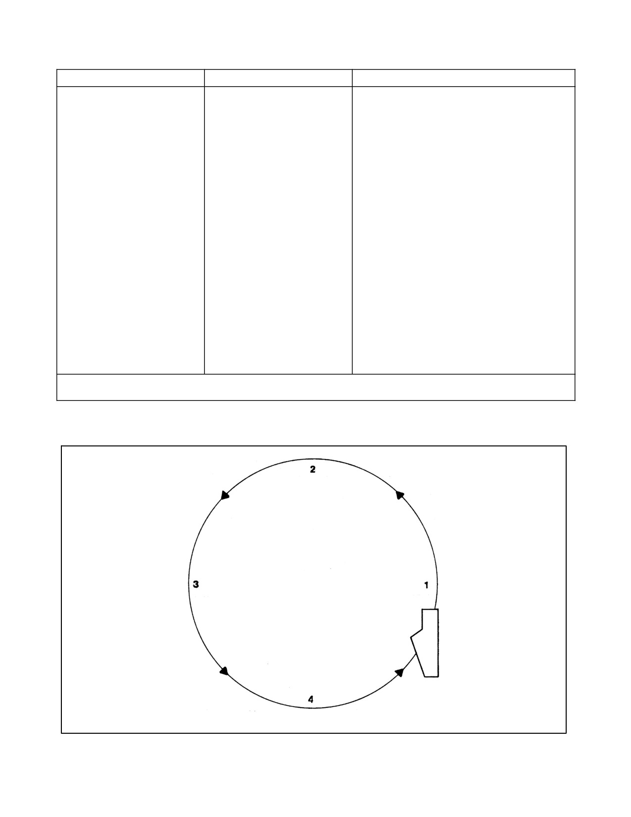
NAVAIR 00-80T-105
EMERGENCY
CARQUALS
DEPLOYED/REFRESHER
4.
Complete electrical failure.
1.
If the carrier can be sighted and a safe
descent and landing approach made, fuel
permitting, orbit keeping the carrier in sight and
descend so as to be at the ship during the
scheduled recovery and/or descend and fly by
ship giving appropriate emergency signal
(Figures 6-9 to 6-11).
2.
If the carrier cannot be located, the pilot should
DR navigate to the prebriefed “emergency
sector/radial” and hold. If not joined by or
unable to join on any escort aircraft, upon
reaching bingo fuel, divert to bingo field if
available.
3.
If no bingo field is available, commence DR
descent/penetration to ship at approximate
approach time, weather and common sense
permitting. If after descent ship is not sighted,
commence square search if practical.
4.
If the carrier or potential rescue ship is not
sighted or if the aircraft/weather combination
precludes a descent, take DR heading to
nearest land. If land is reached, hold at
recommended ejection/bailout altitude and
continue watching for escort; when fuel nears
exhaustion, make controlled ejection/bailout.
Note
Information and instructions should be transmitted to no-radio (NORDO) aircraft on control frequencies and guard.
Figure 6-12. Night Communication Emergencies (Sheet 2)
Figure 6-13. Tanker Rendezvous Pattern
ORIGINAL
6-38

NAVAIR 00-80T-105
6.10.1.2
Case III
The recovery tanker pattern shall be assigned by departure control. It shall be at least 1,000 feet above the overcast
or VMC between layers, but not less than 2,500 feet MSL. The tanker pilot shall advise departure control of the best
altitude and position to conduct emergency tanking. Positive control shall be provided for tanker overcast
penetrations. Departure control shall assist in positioning the tanker near a potential receiver and shall keep the tanker
informed of the potential receiver’s position.
Note
Tanking shall not be attempted below 1,500 feet during Case I/II and 2,500
feet during Case III.
6.10.2 Rendezvous Procedures
6.10.2.1
Rendezvous Low (Day and Night)
When directed to “hawk” (closely monitor) a particular aircraft that is a potential receiver, the tanker pilot shall
position the tanker to be at the 2-o’clock position of the low-state aircraft as it bolters or waves off. The minimum
altitude for rendezvous shall be 1,500 feet day, 2,500 feet night, ensuring a minimum of 500 feet vertical separation
between receiver and tanker aircraft until visual separation can be maintained. When directed, the tanker shall switch
to the potential receiver aircraft’s frequency. If visual contact is not acquired, the controlling agency shall provide
assistance until visual contact is established. The receiver should generally make the final rendezvous on the tanker.
Positive radio communications must be established if the tanker will be rendezvousing on the receiver at night. The
tanker should stream the drogue as the receiver joins, thus expediting plug-in. The tanker pilot shall report to tanker
control the following:
1. When the receiver is taking on fuel
2. When refueling has been completed, the amount of fuel transferred, and update give-away.
6.10.2.2
Rendezvous High/On Top (Day and Night)
Departure control shall provide positive control until visual contact is established. The receiver shall make the final
rendezvous on the tanker and report as previously described.
6.10.3 Recovery Tanking Pattern
After the receiver is engaged, the tanker aircraft shall establish a racetrack pattern in the vicinity of the ship. Unless special
circumstances exist, the tanker should not proceed more than 10 miles ahead of the ship. The downwind leg should be
3 to 5 miles abeam and tanking should be completed prior to reaching a point 6 miles astern to allow for proper pattern
entry. If tanking is done above an overcast, departure control may direct adjustment of the pattern so as to allow for normal
descent and CCA pickup.
6.10.4 Recovery (Case III)
The desire to expedite tanker recovery must not jeopardize flight safety. The recovery tanker shall be given positive
control unless executing an instrument approach procedure published in this section or operating under night
EMCON conditions. The aircraft shall be level during the turn to final bearing and given sufficient clearance to pass
through 6 miles at 1,200 feet.
Note
If recovery tanker is established 1,200 feet abeam, the six mile gate is not
required.
6-39
ORIGINAL

NAVAIR 00-80T-105
6.10.5 Fuel Transfer and Dump Control
Each ship/air wing shall promulgate supplementary instructions that shall include the following instructions.
1. Bingo data for all embarked aircraft.
2. Low state figures (i.e., state at which aircraft will normally be ordered to tank) and amount of fuel to be
transferred to each type aircraft when no divert field is available.
3. Procedures for control of tanker fuel by CATCC.
4. Minimum fuel for barricade engagement.
Except in an emergency, tankers shall obtain clearance from departure control before transferring or dumping fuel.
Departure control shall be advised of any changes of tanker fuel state and give-away as appropriate.
D Shipboard recovery of a tanker aircraft with an extended hose presents a
missile hazard that may be caused by shattering of the drogue/basket as it
strikes the ramp area. Prior to recovery, the flight deck should be cleared
of all but required recovery personnel. Only the controlling LSO should
remain on the platform, and he should utilize the safety net as the aircraft
crosses the ramp. If possible, aircraft adjacent to the landing area should be
respotted forward or struck below to the hangar deck.
D Even though the probability of damage to the aircraft by drogue/basket slap
during a bolter is slight, the pilot should be aware of this possibility.
6.11
DIVERSION OF AIRCRAFT
The air operations officer or the air officer shall normally be responsible for making the recommendation to the
commanding officer as to which aircraft should be diverted in the interest of flight safety. The air operations officer
shall, if practicable, determine the condition of the navigation, communication, and lighting facilities of divert field
prior to the first Case III recovery. The following factors shall be considered when anticipating a divert:
1. Aircraft fuel state
2. Bearing and distance of field
3. Weather at divert field, current and forecast
4. En route upper level winds
5. Suitability of field for type of aircraft
6. Navigational assistance available
7. Aircraft mechanical condition
8. Ordnance restrictions
ORIGINAL
6-40
NAVAIR 00-80T-105
9. Condition of carrier deck
10. Availability of tankers
11. Pilot performance.
CATCC/CDC shall be alerted to the impending divert of an aircraft or group of aircraft and shall take control of the
aircraft when diverted. CDC shall also ensure the ship’s lookouts are alerted to the forthcoming divert, model aircraft,
side number, and on what relative bearing the aircraft is expected to depart the ship.
If the tanker refueling hose cannot be retracted, the hose shall be guillotined prior to recovery. If the hose fails to
separate, the aircraft shall be diverted to a suitable landing field. When the situation prevents an aircraft divert and
it is equipped with an external refueling store, the store shall be jettisoned prior to attempting a carrier landing. If
the hose cannot be guillotined and/or the refueling store jettisoned, normal arrested landing procedures shall be
utilized.
When it is determined to divert an aircraft, approach control shall notify the pilot by passing the following information
only: “(call sign) signal divert/bingo, (name of field) passing angles 2.5 go button (XX).” After the switch to departure
control once above 2,500 feet, the pilot shall be advised to check gear up/hook up and also have information relayed
regarding the magnetic heading and the distance to the divert field. A readback of diverting instructions from the pilot
or flight leader is mandatory on departure frequency. While under positive control and en route to the divert airfield,
any additional information available shall be provided the pilot concerning latest en route and field weather, squawk,
altimeter setting, and position from which divert is being initiated. If operating outside an ADIZ boundary, the CDC
controller shall provide the pilot with the necessary ADIZ information. The appropriate Air Defense Sector shall be
advised of the diverted aircraft’s departure point, ADIZ penetration point, time of penetration, altitude, ETE,
destination, and any additional information that may be pertinent to safety of flight. The CDC controller shall
maintain a radar plot and radio monitor on all diverted aircraft as long as possible and retain responsibility for the
aircraft until positive radar handoff to FACSFAC/ARTCC or other appropriate controlling agency.
Under IMC, the aircraft shall be instructed to shift to the appropriate airspace controlling agency (FAA or other)
frequency after the additional divert information has been received. Once communications have been established
with this controlling agency, the flight plan particulars shall be furnished, including the ADIZ penetration
information for relay to an air defense sector. The aircraft will receive a clearance. If communications cannot be
established, as is often the case, the pilot should file using GCI Common.
The air operations officer shall ensure a divert flight plan is transmitted to the appropriate divert airfield and similar
information to the pertinent air defense system agency should an ADIZ penetration be involved; he is also responsible
for receipt of an arrival report on the diverted aircraft. The pilot shall ensure an arrival report is transmitted
immediately upon landing via the most expeditious means (i.e., POTS, HF/UHF radio, INMARSAT, immediate
message, etc.).
Squadron or unit commanders and the air operations officer are jointly responsible for ensure aircraft performance
data pertinent to divert is available to and understood by air control personnel.
6-41/(6-42 blank)
ORIGINAL
NAVAIR 00-80T-105
CHAPTER 7
Aircraft and Weapons Handling Procedures
7.1
GENERAL REQUIREMENTS
All aircraft movement shall be controlled by designated aircraft directors. Aircraft shall be moved only with the
express authority of either the air officer, aircraft handling officer, flight deck officer, hangar deck officer, or air
department duty officer except in cases of emergency. Aircraft handling personnel are specifically charged with the
responsibility of reporting to higher authority any observed unsafe practices or any condition that may affect the
safety of personnel or equipment.
Note
The abrasive qualities of the flight/hangar deck nonskid shall be maintained
in good condition. Accumulated oils, grease, etc., shall be cleaned from the
flight/hangar deck periodically or when dangerous conditions exist.
When the ship is at flight quarters, the OOD shall ensure all anticipated turns are passed to PriFly with sufficient lead
time to enable deck crews to secure aircraft movement/position aircraft accordingly.
It is the responsibility of the aircraft handling officer to begin a respot early enough to avoid unnecessary haste;
however, when aircraft are airborne, the desirability of maintaining a ready deck for as long as possible should be
kept in mind. The tempo of aircraft movements shall be governed by the deck stability, prevailing winds, weather
conditions, and nonskid conditions. Primary consideration shall be given to safety of personnel.
During aircraft arming and dearming evolutions, the area ahead of and immediately behind the aircraft shall be kept
clear.
Communications incident to aircraft handling must be in accordance with the existing EMCON condition.
7.2
BRIEFING
Prior to any major respot, the aircraft handling officer shall brief the flight deck officer, hangar deck officer, and other
key aircraft handling personnel. This briefing shall include expected wind and deck conditions and any other
information pertinent to safety.
7.3
MAINTENANCE LIAISON
It is imperative that the aircraft handling officer be provided accurate information regarding the status as well as the
existing and expected maintenance requirements (tail pull, wingspread, blade track, etc.) of every aircraft on board.
For this purpose, aircraft status and maintenance request boards shall be maintained in flight deck control.
An air wing maintenance liaison officer or his representative will be on duty at all times during flight quarters or
general quarters. His primary duty is to ensure the aircraft handling officer is kept continuously apprised of aircraft
status and maintenance requirements and to maintain liaison between the air department and squadron line and
maintenance personnel. His normal station is flight deck control; however, he is free to move about the flight and
hangar decks as necessary to perform his duties.
Changes in aircraft status will channel through the air wing maintenance liaison officer and shall be entered on the
aircraft status board. Entries and changes to the maintenance request board shall be handled in the same manner. To
7-1
ORIGINAL
NAVAIR 00-80T-105
assist the air wing maintenance liaison officer in the performance of his duties, the following is required of the
squadron maintenance officers.
1. Provide the air wing maintenance liaison officer with a complete aircraft status report prior to scheduled flight
quarters or as early as possible during unscheduled flight quarters or general quarters. This report must show
aircraft status, discrepancies on
“down” aircraft, estimated time of repair, special requirements for
maintenance, any fuel other than JP-5 on board, and any additional information of interest to the aircraft
handling officer.
2. Immediately report all changes in aircraft status to the maintenance liaison officer.
3. Immediately following each recovery, report the status of all aircraft just recovered and advise whether or not
“down” aircraft can be repaired before the next launch.
4. Periodically during flight operations, and as soon as possible after the final recovery, verify the maintenance
request board.
The air wing maintenance liaison officer is responsible for the overall performance of plane captains and
troubleshooters. He shall ensure no aircraft is placed on jacks or otherwise immobilized without permission from the
aircraft handling officer. He shall also obtain permission for engine maintenance turnups from the aircraft handling
officer or integrity watch officer, as appropriate.
Maintenance functions involving electronic emissions will be limited by existing EMCON conditions.
7.4
EQUIPMENT
The flight deck officer is responsible for ensuring all tractors, mobile firefighting equipment, towbars, chocks, and
other equipment used in the handling of aircraft on the flight deck are in satisfactory condition and are properly
utilized. The hangar deck officer has a similar responsibility with regard to the equipment used on the hangar deck.
Tractor drivers shall under no circumstances operate a tractor with defective brakes or steering. Discrepancies shall
immediately be reported to competent authority.
Note
Crash and salvage crews shall not be utilized as tow tractor operators during
aircraft start, launch, recovery, and respot operations.
Defective towbars, chocks, and tiedowns shall immediately be taken out of service and turned in for repair. Towbars,
chocks, and tiedowns not in use shall be neatly stowed in designated stowage spaces. Each squadron shall provide
its plane captains with canvas bags or other suitable containers for tiedown stowage. Tiedowns removed from an
aircraft being moved shall not be hung from any part of the aircraft because of the hazard presented to personnel and
equipment.
7.5
MOVEMENT OF AIRCRAFT
In preparing to move an aircraft (taxi, tow, by hand), the director shall ensure the following:
1. The cockpit is manned by a qualified brake rider.
2. The towbar is securely attached to the aircraft and to the tractor or, if the aircraft is to be moved by hand, he
shall ensure the towbar is properly tended by another director or specifically designated towbar man.
ORIGINAL
7-2

NAVAIR 00-80T-105
Towing of turboprop aircraft with an engine running is prohibited. Towing
other type aircraft with engines running is hazardous and should be avoided
whenever possible.
3. All chocks, tiedowns, power cables, and other servicing/securing devices are removed prior to moving the
aircraft.
CAUTION
Tiedowns and chocks shall not be removed prior to attachment of the
towbar to the tractor.
4. If weapon loading/downloading is in progress, assurance is received from the ordnance crew leader that the
aircraft is safe to move insofar as weapons are concerned.
5. Adequate clearance exists to permit safe movement.
6. Safety men are posted as required to ensure clearance if in close proximity to other aircraft, bulkheads, or
obstructions.
7. The qualified brake rider signifies he has checked the aircraft brakes, that adequate braking pressure is
available, and they appear to be in proper working order.
8. All personnel except those necessary for the move are well clear of the aircraft.
Working or passing beneath a moving aircraft is extremely hazardous. This
practice is prohibited except for catapult hookup, recovery operations,
chock walking, and emergencies.
In manning the cockpit of an aircraft to be moved, the qualified brake rider shall perform the following:
1. Ensure ejection seat safety pins are installed and safety pins are in place in the landing gear/auxiliary tanks
as appropriate.
2. Adjust the seat and rudder pedals as required to ensure the ability to fully apply the brakes and see the director
at the same time.
3. Ensure the windshield and side panels are clear of grease, cleaning compound, or any other film which might
limit visibility.
4. Conditions permitting, open cockpit canopy, windows, or overhead hatches.
5. Ensure adequate braking pressure is available and that the brakes appear to be in proper working order.
7-3
ORIGINAL