Siemens SITRANS P. Operating Instructions (2019) - page 13

SITRANS P measuring instruments for pressure
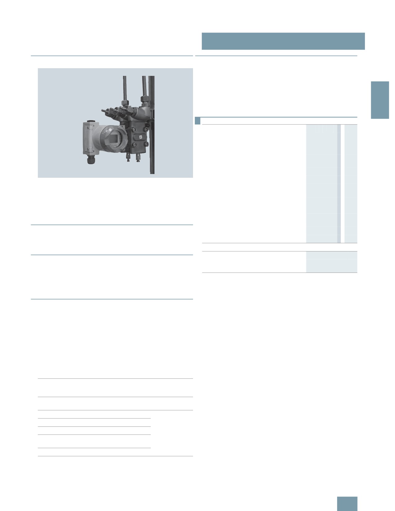
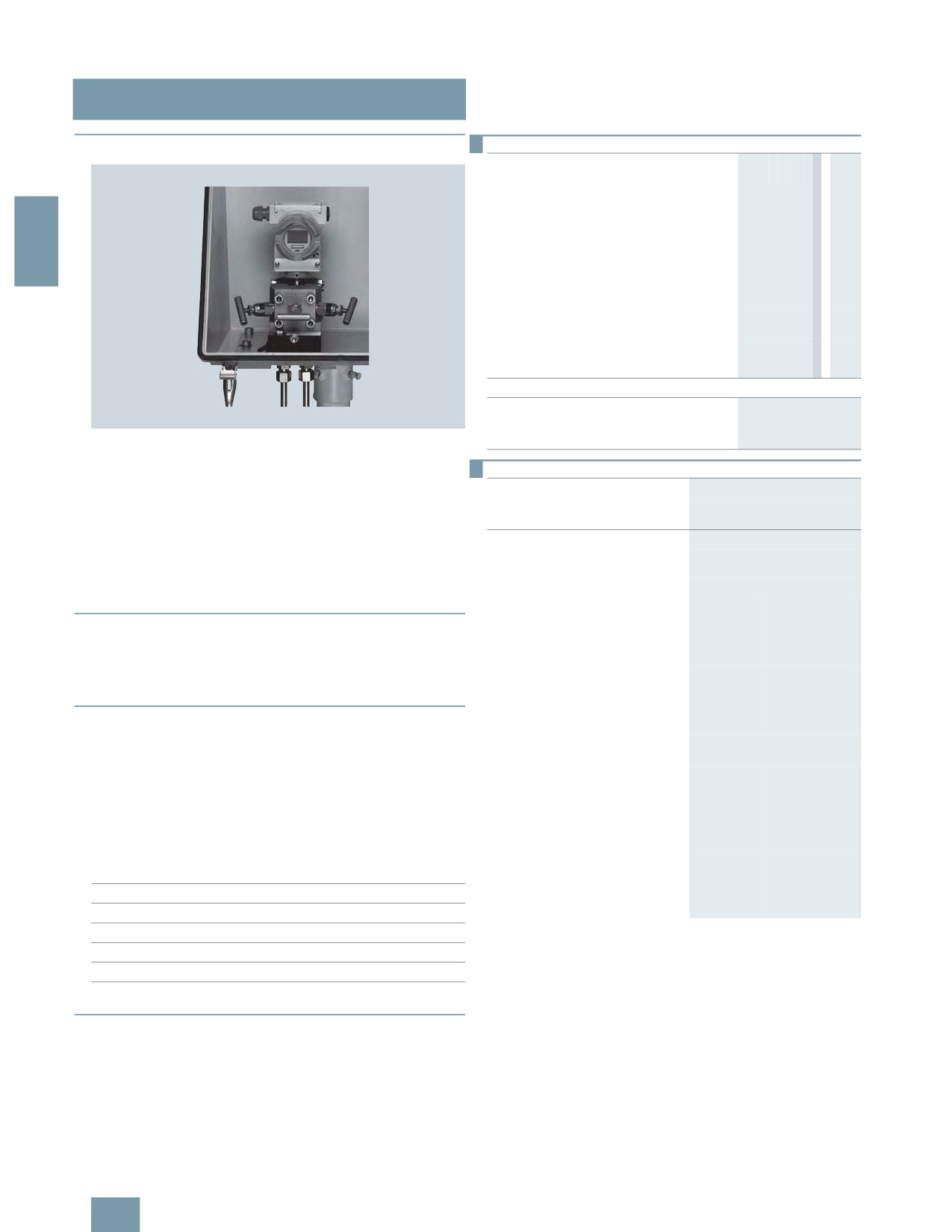
Fitttings - Shut-off valves for gage and absolute pressure transmitters
2-way valve manifolds DN 5
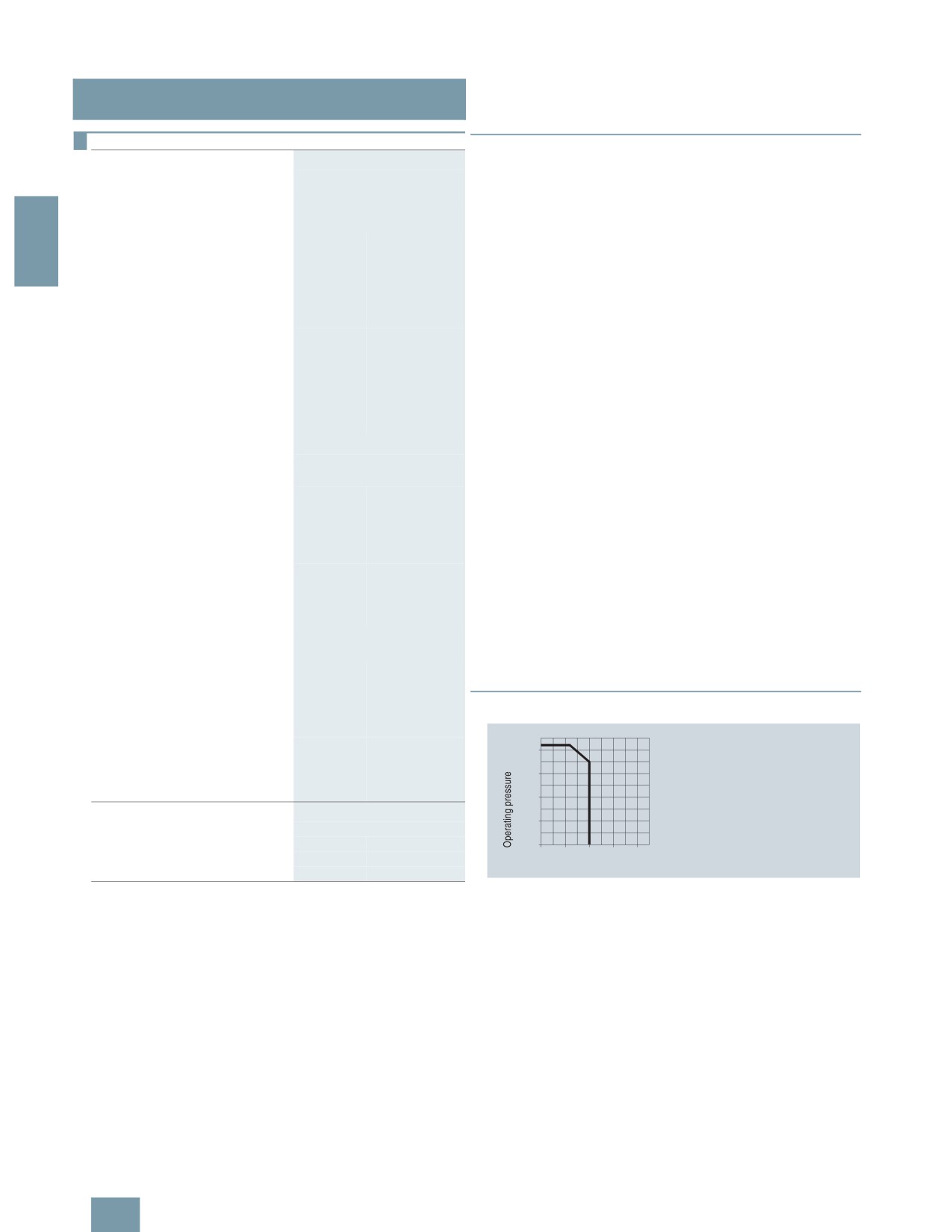
■Characteristic curves
+
)
&
2
&
)
D
2-way valve manifold DN 5, permissible working pressure as a function
of the permissible working temperature
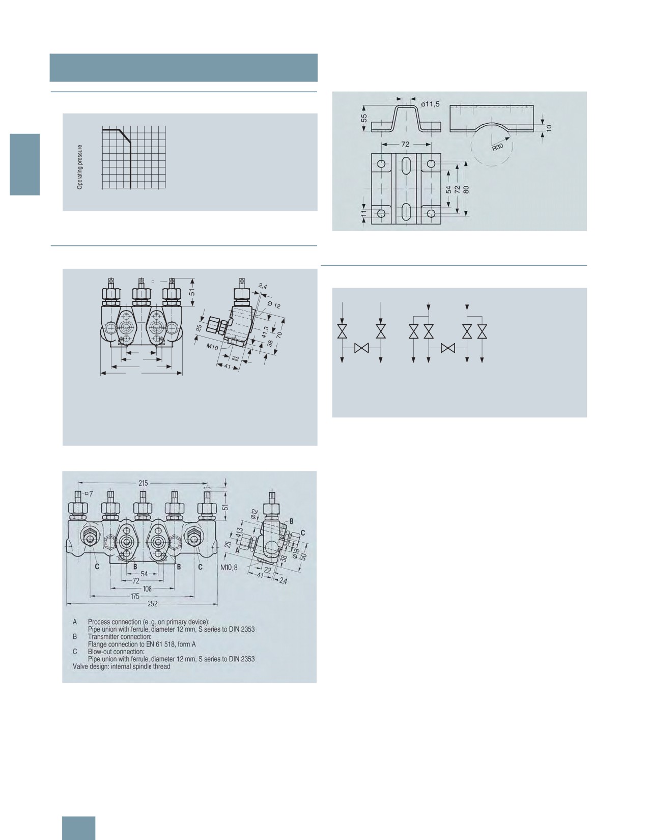
■Dimensional drawings
2-way valve manifold DN 5 (7MF9401-2J/-2K) for connection to pressure
gages and pressure transmitters, dimensions in mm
(
$
54
$!
1
11$
* = %;%
"
4
#4
#
* = += ? ; 7$B
1
(
"
>
#
5
! -%)7
& &
> & &
C &
!
#
!
5
!
2-way valve manifold DN 5 (7MF9401-2E/-2F) for flanging, dimensions in
mm
Mounting plate 7MF9006-6.. (M11, M12) for valve manifold, dimensions
in mm
■Schematics
"
(
>
1
(
"
>
!F
Connection diagram of the 2-way valve manifolds
2/200

SITRANS P measuring instruments for pressure
Fitttings - Shut-off valves for differential pressure transmitters
2-, 3- and 5-spindle valve manifolds DN 5
■Overview
Selection and Ordering data
Order No.
Valve manifolds DN 5
7MF9411 -77A
for liquids and gases, for flanging to pressure
transmitters for absolute and differential
pressure, max. working pressure 420 bar
(order accessory set with Order code),
without certificate
2
• 2-spindle valve manifold
5A
• 3-spindle valve manifold
5B
• 5-spindle valve manifold
5C
Accessories
Factory test certificate EN 10204-2.2
7MF9000-8AB
Material acceptance test certificate
7MF9000-8AD
EN 10204-3.1
Selection and Ordering data
Order code
Order No.
Further designs1)
The 2-spindle, 3-spindle and 5-spindle valve manifolds
Please add "-Z" to Order No. and
specify Order code.
7MF9411-5.. are for pressure transmitters for absolute pressure
or differential pressure.
Accessory set to EN
(connection between valve manifold
The valve manifolds are used to shut off the differential pressure
and pressure transmitter)
lines and to check the pressure transmitter zero.
for valve manifold 7MF9411-5A.
The 2-spindle and the 5-spindle valve manifold enable in addi-
2x screws 7/16-20 UNF x
K35
7MF9411-7DB
tion venting on the transmitter side and checking of the pressure
1¾ inch to ASME B18.2.1; chromized
transmitter characteristic.
steel
1x gasket made of PTFE,
■ Benefits
max. permissible 420 bar, 80 °C
• Max. working pressure 420 bar
2x screws 7/16-20 UNF x
K45
7MF9411-7DC
1¾ inch to ASME B18.2.1; stainless
• Each available in version for oxygen
steel
1x gasket made of PTFE,
max. permissible 420 bar, 80 °C
■Application
for valve manifold 7MF9411-5B. and
The spindle valve manifolds DN 5 are designed for liquids and
-5C.
gases
4x screws 7/16-20 UNF x
K36
7MF9411-5DB
Each is available in a version for oxygen on request
1¾ inch to ASME B18.2.1; chromized
steel
2x flat gaskets made of PTFE,
■Design
max. permissible 420 bar, 80 °C
All versions of the valve manifolds have a process connection ½-
4x screws 7/16-20 UNF x
K46
7MF9411-5DC
14 NPT. The connection for the pressure transmitter is always
1¾ inch to ASME B18.2.1; stainless
steel
designed as a flange connection to EN 61518, form B . The 2-
2x flat gaskets made of PTFE,
spindle and the 5-spindle valve manifold have in addition a vent
max. permissible 420 bar, 80 °C
and test connection ¼-18 NPT.
2)
Accessory set to DIN
The valves have an external spindle thread.
(connection between valve manifold
and pressure transmitter)
Materials used
for valve manifold 7MF9411-5A.
Component
Material
Mat. No.
2x screws M10x45 to DIN EN 24014;
K15
7MF9411-7BB
Housing
X 2 CrNiMo 17 13 2
1.4404/316L
chromized steel
Cones
X 6 CrNiMoTi 17 12 2
1.4571/316Ti
2x washers Ø 10.5 mm to DIN 125;
1x gasket made of PTFE,
Spindles
X 2 CrNiMo 18 10
1.4404/316L
max. permissible 420 bar, 80 °C
Head parts
X 5 CrNiMo 18 10
1.4401/316
2x screws M10x45 to DIN EN 24014;
K25
7MF9411-7BC
Packings
PTFE
-
stainless steel
2x washers Ø 10.5 mm to DIN 125,
stainless steel;
■Function
1x gasket made of PTFE,
max. permissible 420 bar, 80 °C
Functions of all valve manifolds:
• Shutting off the differential pressure lines
• Checking the pressure transmitter zero
Additional functions of the 2-spindle and 5-spindle valve mani-
folds through the vent and test connection:
• Venting on the transmitter side
• Checking the pressure transmitter characteristic
2/201
SITRANS P measuring instruments for pressure
Fitttings - Shut-off valves for differential pressure transmitters
2-, 3- and 5-spindle valve manifolds DN 5
Selection and Ordering data
Order code
Order No.
■Accessories
Further designs1)
Accessory set for 2-, 3- and 5-spindle valve manifolds
Please add "-Z" to Order No. and
specify Order code.
2-spindle valve manifold DN 5
for valve manifolds 7MF9411-5B.
• K35: 2 screws 7/16-20 UNF x 1¾ inch to ASME B18.2.1,
and -5C.
1 flat gasket
2
4x screws M10x45 to DIN EN 24014;
K16
7MF9411-6BB
• K15: 2 screws M10x45 to DIN EN 24014, 2 washers,
chromized steel
1 flat gasket
4x washers Ø 10.5 mm to DIN 125;
2x flat gaskets made of PTFE,
3-spindle and 5-way valve manifold DN 5
max. permissible 420 bar, 80 °C
• K36: 4 screws 7/16-20 UNF x 1¾ inch to ASME B18.2.1,
Flange connection with M10 screws
2 flat gaskets
only permissible up to PN 160.
• K16: 4 screws M10x45 to DIN EN 24014, 4 washers,
4x screws M10x45 to DIN EN 24014;
K26
7MF9411-6BC
stainless steel
2 flat gaskets
4x washers Ø 10.5 mm to DIN 125,
Washers Ø 10.5 to DIN 125
stainless steel;
2x flat gaskets made of PTFE,
Flat gaskets made of PTFE, max. 420 bar, 80 °C
max. permissible 420 bar, 80 °C
Flange connection with M10 screws
Note: Flange connection with M10 screws only permissible up to
only permissible up to PN 160.
PN 160!
Mounting plate
Mounting plate
• for valve manifold, made of
Made of electrogalvanized sheet-steel
electrogalvanized sheet-steel
- for wall mounting or for securing
M11
7MF9006-6EA
• M11: For wall mounting or for securing on rack (72 mm grid)
on rack (72 mm grid), weight
Scope of delivery:
0.5 kg
- 1 mounting plate with bolts for mounting on valve manifold
Scope of delivery:
• M12: For pipe mounting
1 mounting plate with bolts for
Scope of delivery:
mounting on valve manifold
- 1 mounting plate M11
- for pipe mounting, weight 0.7 kg
M12
7MF9006-6GA
Scope of delivery:
- 2 pipe brackets with nuts and washers for pipes with max.
1x mounting plate M11, 2x pipe
Ø 60.3 mm
brackets with nuts and washers
(for pipe with max. Ø 60.3 mm)
Valve manifold 100 bar, suitable for oxygen
• S12: For 2-way valve manifold
• for valve manifold, made of
stainless steel
• S13: For 3-way valve manifold
- for wall mounting or for securing
M21
7MF9006-6EC
• S13: For 5-way valve manifold
on rack (72 mm grid), weight
0.5 kg
Scope of delivery:
■Characteristic curves
1 mounting plate with bolts for
mounting on valve manifold
+
- for pipe mounting, weight 0.7 kg
M22
7MF9006-6GC
Scope of delivery:
)
1x mounting plate M11, 2x pipe
&
brackets with nuts and washers
(for pipe with max. Ø 60.3 mm)
Valve manifold 100 bar
Suitable for oxygen
• for 7MF9411-5A.
S12
• for 7MF9411-5B.
S13
&
)
D
• for 7MF9411-5C.
S14
1) When ordering accessory set or mounting together with the valve
Valve manifolds PN 5 (7MF9411-5..), permissible working pressure as a
manifolds, please use Order code; otherwise use Order No.
function of the permissible working temperature
2) Flange connections to DIN 19213 only permissible up to 160!
2/202

SITRANS P measuring instruments for pressure
Fitttings - Shut-off valves for differential pressure transmitters
2-, 3- and 5-spindle valve manifolds DN 5
■Dimensional drawings
2
(
#8
0= >
>
1
#B
+= ?
; 7$4
1
" C
)
#J
7= >
Mounting plate 7MF9006-6.. (M11, M12) for valve manifold, dimensions
C &
!
#
@
!
5
!
in mm
2-spindle valve manifold DN 5 (7MF9411-5A.), dimensions in mm
■Schematics
*
*
- .
2-spindle, 3-spindle and 5-spindle valve manifold DN 5, connections
(
#8
0= >
>
1
#4
+= ?
; 7$4
1
C &
!
#
@
!
5
!
3-spindle valve manifold DN 5 (7MF9411-5B.), dimensions in mm
(
#8
0= >
>
1
#B
+= ?
; 7$4
1
" C
)
#J
7= >
C &
!
#
@
!
5
!
5-spindle valve manifold DN 5 (7MF9411-5C.), dimensions in mm
2/203
SITRANS P measuring instruments for pressure
Fitttings - Shut-off valves for differential pressure transmitters
Multiway cocks PN 100
■Overview
■ Technical specifications
Multiway cocks PN 100
Measured medium Water, non-aggres-
Aggressive liquids,
sive liquids and
gases and vapors
gases
2
Material
P250GH, mat. No.:
X 6 CrNiMoTi 17 12 2,
1.0460
mat. No. 1.4571/316Ti
Connections
Steel, for pipe
Stainless steel, for
Ø 12 mm, L series
pipe Ø 12 mm, L
series
• Process connection
2 bulkhead glands
• Connection for blow-
Pipe union with ferrule
ing out
Max. permissible
200 °C
working temperature
Max. permissible
100 bar (up to max. 60 °C)
working pressure
Weight
2.5 kg
Multiway cock PN 100 (7MF9004-1P.) for differential pressure transmitters
Selection and Ordering data
Order No.
The multiway cock PN 100 can be flanged to pressure transmit-
Multiway cock PN 100
7MF9004 -77A
ters for differential pressure.
for flanging to pressure transmitters, weight
2.5 kg (without accessory set),
■ Benefits
without certificate
• Version available for aggressive liquids, gases and vapors
for water and non-aggressive gases and
1P
vapors
• Robust design
for aggressive liquids, gases and vapors
1Q
• Oil-free and grease-free version possible
Accessories
• One-hand operation
Factory test certificate EN 10204-2.2
7MF9000-8AB
■Application
Material acceptance test certificate
7MF9000-8AD
EN 10204-3.1
The PN 100 multiway cock is available in versions for aggressive
and non-aggressive liquids, gases and vapors.
Selection and Ordering data
Order code
Order No.
Further designs1)
■Design
Please add "-Z" to Order No. and
specify Order code.
The multiway cock can be flanged with four screws to pressure
transmitters for differential pressure.
Accessory set to EN
(required for flanging, weight 0.2 kg)
The PN 100 has 2 process connections and one blow-out con-
4x screws 7/16-20 UNF x 1 inch to
L31
7MF9004-5CC
nection. A steel version of the multiway cock is available for non-
ASME B18.2.1; chromized steel
aggressive media, and a stainless steel version for aggressive
2x gaskets made of PTFE, max.
media. The housing is forged in one piece. The switching lever
permissible temperature 80 °C
is removable.
Accessory set to DIN
(required for flanging, weight 0.2 kg)
Sealing can be improved during operation.
4x screws M10x25 to DIN EN 24017;
Note: An accessory set is always required for flanging of the
chromized steel
multiway cock to a differential pressure transmitter.
4x washers Ø 10.5 mm to DIN 125;
2x gaskets made of PTFE, max.
permissible temperature 80 °C
■Function
• Standard design
L11
7MF9004-6AD
• Shutting off the differential pressure lines
• Version for oxygen (together with
L15
7MF9004-6AE
• Blowing out the differential pressure lines
Order code S11
• Testing the pressure transmitter zero
Multiway cock in oil-free and
grease-free design
Max. PN 63 (instead of PN 100),
S11
BAM-tested lubricant, gasket suit-
able for oxygen measurement (only
with Order No. 7MF9004-1Q.Z)
Mounting bracket
M13
7MF9004-6AA
Required for wall mounting or for
securing on rack (72 mm grid),
made of electrogalvanized sheet-
steel, weight 0.85 kg
1) When ordering accessory set or mounting together with the multiway cock,
please use Order code; otherwise use Order No.
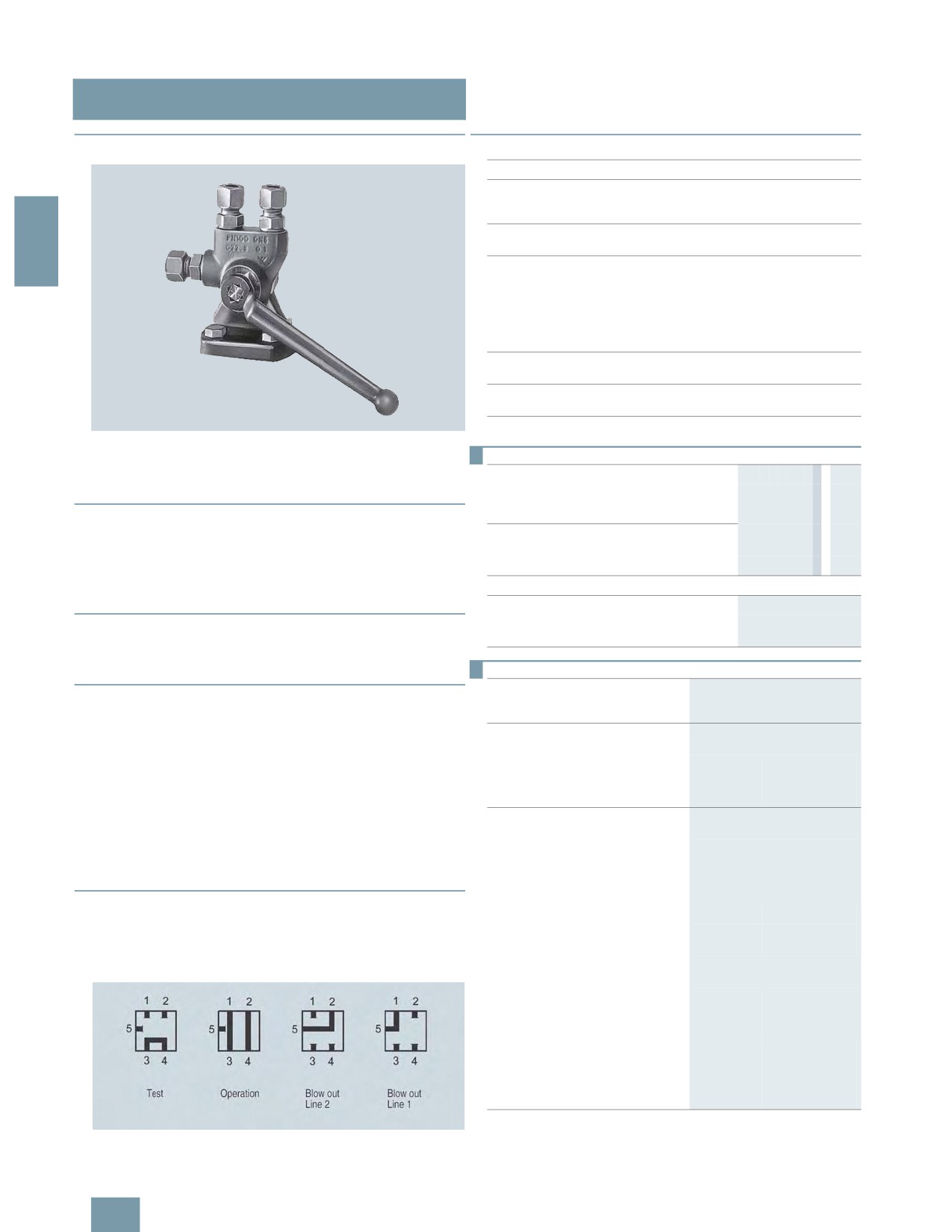
Cock positions; the symbols are printed on the cock
2/204

SITRANS P measuring instruments for pressure
Fitttings - Shut-off valves for differential pressure transmitters
Multiway cocks PN 100
■Accessories
■Dimensional drawings
Accessory set for multiway cock PN 100
• L31: 4 screws 7/16-20 UNF x 1 inch, 2 flat gaskets
• L11: 4 screws M10x25 to DIN EN 24017, 4 washers, 2 flat gas-
kets
2
• L15 (suitable for oxygen): 4 screws M10x25 to DIN EN 24017,
4 washers, 2 flat gaskets
Washers Ø 10.5 to DIN 125
Flat gaskets made of PTFE, max. permissible temperature 80 °C
Multiway cock in oil-free and grease-free design
• S11 (only for aggressive liquids, gases and vapors
(7MF9004-1Q.)): Max. PN 63 (instead of PN 100), BAM-tested
lubricant, gasket suitable for oxygen
Mounting brackets
• M13: Required for wall mounting or for securing on rack
(72 mm grid); made of electrogalvanized sheet-steel
■Characteristic curves
Multiway cock 7MF9004-1P. for flanging to pressure transmitters for dif-
ferential pressure, dimensions in mm
Multiway cock PN 100, permissible operating pressure as a function of
the permissible operating temperature
)
1
5
2
)
1
Mounting bracket 7MF9004-6AA (M13), dimensions in mm
2/205

SITRANS P measuring instruments for pressure
Fitttings - Shut-off valves for differential pressure transmitters
3-way and 5-way valve manifolds DN 5
■Overview
■Function
• Shutting off the differential pressure lines
• Checking the pressure transmitter zero
• In addition, the five-way valve manifold permits blowing out of
the differential pressure lines.
2
Selection and Ordering data
Order No.
3-way valve manifold DN 5
7MF9410 -77A
for flanging to pressure transmitters for differ-
ential pressure, process connection: Pipe
union with ferrule, max. working pressure
420 bar, weight 2.9 kg (order accessory set
and mounting plate with Order code),
without certificate
• for non-aggressive liquids and gases
1E
• for aggressive liquids and gases
1F
5-way valve manifold DN 5
for flanging to pressure transmitters for differ-
The three-spindle and five-spindle valve manifolds DN 5
ential pressure, process connection: Pipe
(7MF9410-1../-3..) are used to shut off the differential pressure
union with ferrule, max. working pressure
420 bar, weight 4.4 kg (order accessory set
lines and to check the transmitter zero.
and mounting plate with Order code),
In addition, the five-way valve manifold permits blowing out of
without certificate
the differential pressure lines.
• for non-aggressive liquids and gases
3E
• for aggressive liquids and gases
3 F
■ Benefits
Accessories
• Available for aggressive and non-aggressive liquids and
Factory test certificate EN 10204-2.2
7MF9000-8AB
gases
Material acceptance test certificate
7MF9000-8AD
• Max. working pressure 420 bar, with version for oxygen max.
EN
10204-3.1
100 bar
■Application
The 3-way and 5-way valve manifolds are available in versions
for aggressive and non-aggressive liquids and gases.
Mounting plates are available for wall mounting, for securing to
mounting racks or for pipe mounting.
■Design
The process connection of the 3-way and 5-way valve manifolds
is a pipe union with ferrule.
Both valve manifolds have 2 flange connections for connecting
a pressure transmitter.
In addition, the five-way valve manifold has 2 blow-out connec-
tions.
Depending on the version the valve manifold has either 3 or 5
valves, each with an internal spindle thread.
Materials used
For non-aggressive liquids and
For aggressive
gases
liquids and
gases
Component Material
Mat. No. Material Mat.
No.
Housing
P250GH
1.0460
X 6
1.4571/
CrNiMoTi
316Ti
Head parts C 35
1.0501
17 12 2
Spindles
X 12 CrMoS 17
1.4104
Cones
X 35 CrMo 17 hardened
1.4122
and tempered
Valve seats X 6 CrNiMoTi 17 12 2
1.4571/
316Ti
Packings
PTFE
-
PTFE
-
2/206

SITRANS P measuring instruments for pressure
Fitttings - Shut-off valves for differential pressure transmitters
3-way and 5-way valve manifolds DN 5
Selection and Ordering data
Order code
Order No.
■Accessories
Further designs1)
Accessory set for 3-way and 5-way valve manifold DN 5 for
Please add "-Z" to Order No. and
flanging
specify Order code.
• B31: 4 screws 7/16-20 UNF x 21/8 inch to ASME B18.2.1,
Accessory set to EN
2 flat gaskets
(required for flanging, weight 0.2 kg)
2
• B34: 4 screws 7/16-20 UNF x 21/8 inch to ASME B18.2.1,
4x screws 7/16-20 UNF x
B31
F)
7MF9010-5CC
2 O-rings (FPM 90)
2
1/8
inch to ASME B18.2; chromized
• B11: 4 screws M10x55 to DIN EN 24014, 4 washers,
steel
2 flat gaskets
2x flat gaskets made of PTFE,
max. permissible 420 bar, 80 °C
• B15 (suitable for oxygen): 4 screws M10x55 to DIN EN 24014,
4 washers, 2 flat gaskets
4x screws 7/16-20 UNF x
B34
7MF9410-5CA
21/8 inch to ASME B18.2; chromized
• B16: 4 screws M10x55 to DIN EN 24014, 4 washers,
steel
2 O-rings (FPM 90)
2x O-rings to DIN 3771,
20 x 2.65 - S - FPM90, max. permiss-
Washers Ø 10.5 to DIN 125
ble 420 bar, 120 °C
Flat gaskets made of PTFE, max. 420 bar, 80 °C
Accessory set to DIN2)
O-ring to DIN 3771, 20 x 2.65 - S - FPM90, max. 420 bar, 120 °C
(required for flanging, weight 0.2 kg)
Note: M10 screws only permissible up to PN 160!
4x screws M10x55 to DIN EN 24014;
chromized steel
Mounting plate
4x washers Ø 10.5 mm to DIN 125;
2x flat gaskets made of PTFE,
Made of electrogalvanized sheet-steel
max. permissible 420 bar, 80 °C
• M11: For wall mounting or for securing on rack (72 mm grid)
• Standard design
B11
7MF9010-6AD
Scope of delivery:
• Version for oxygen
B15
7MF9010-6AE
- 1 mounting plate 7MF9006-6EA with bolts for mounting on
valve manifold
4x screws M10x55 to DIN EN 24014;
B16
7MF9010-6CC
chromized steel
• M12: For pipe mounting
4x washers Ø 10.5 mm to DIN 125;
Scope of delivery:
2x O-rings to DIN 3771,
- 1 mounting plate M11
20 x 2.65 - S - FPM90, max. permiss-
- 2 pipe brackets with nuts and washers for pipes with max.
ble 420 bar, 120 °C
Ø 60.3 mm
Mounting plate
Valve manifold 100 bar, suitable for oxygen
for valve manifold, made of
electrogalvanized sheet-steel
S12: Only in combination with versions for aggressive liquids
for wall mounting or for securing on
M11
7MF9006-6EA
and gases
rack (72 mm grid), weight 0.5 kg
Scope of delivery:
1 mounting plate with bolts for
mounting on valve manifold
for pipe mounting, weight 0.7 kg
M12
7MF9006-6GA
Scope of delivery:
1x mounting plate M11, 2x pipe
brackets with nuts and washers
(for pipe with max. Ø 60.3 mm)
Valve manifold 100 bar
suitable for oxygen
for 7MF9410-1F
S13
for 7MF9410-3F
S14
1) When ordering accessory set or mounting together with the valve
manifolds, please use Order code; otherwise use Order No.
2) Flange connections to DIN 19213 only permissible up to PN 160!
F) Subject to export regulations AL: 9I999, ECCN: N.
2/207
SITRANS P measuring instruments for pressure
Fitttings - Shut-off valves for differential pressure transmitters
3-way and 5-way valve manifolds DN 5
■Characteristic curves
F
0
%
2
%
0
D"
1
Permissible operating pressure as a function of the permissible operating
temperature
Mounting plate 7MF9006-6.. (M11, M12) for valve manifold, dimensions
in mm
■Dimensional drawings
■Schematics
(
(
(
(
(
>
1
" C
)
"
"
>5
& &
B&
& &
1
4
!4
1
4
!4
H
!
(
$
#
#
1
! &
%#
H
!
!
!
&
54
$!
1
11$
* = %;%
>
1
#
B
+= ?
; 7$4
1
(
3-way and 5-way valve manifolds, connections
C &
!
#
!
5
!
3-way valve manifold DN 5 (7MF9410-1..), dimensions in mm
5-way valve manifold DN 5 (7MF9410-3..), dimensions in mm
2/208
SITRANS P measuring instruments for pressure
Fitttings - Shut-off valves for differential pressure transmitters
3-way valve manifold DN 8
■Overview
■Function
The 3-way valve manifold DN 8 performs two functions as stan-
dard:
• Shutting off the differential pressure lines
• Checking the pressure transmitter zero
2
All versions are also available with a test connection, to which a
test device for checking the pressure transmitter characteristic
can be connected.
Selection and Ordering data
Order No.
3-way valve manifold DN 8
7MF9416 -77A
for flanging to pressure transmitters for differ-
ential pressure, max. working pressure
420 bar, (order accessory set and mounting
plate with Order code), without certificate
for non-aggressive liquids and gases
procedss connection: Pipe union with ferrule
• without test connection
1B
• with test connection
1C
The 3-way valve manifold DN 8 (7MF9416-1../-2..) is for pressure
for non-aggressive liquids and gases
transmitters for differential pressure. It is used to shut off and
procedss connection: Welding pin Ø 14 x 2.5
blow out differential pressure lines and to test the pressure trans-
mitter zero.
• without test connection
2C
In the designs with a test connection, a test device can be con-
• with test connection
2D
nected to test the pressure transmitter characteristic.
for aggressive liquids and gases
process connection: Pipe union with ferrule
■ Benefits
• without test connection
1D
• For aggressive and non-aggressive liquids and gases
• with test connection
1E
• The maximum working pressure is 420 bar.
Accessories
Factory test certificate EN 10204-2.2
7MF9000-8AB
■Application
Material acceptance test certificate
7MF9000-8AD
The 3-way valve manifold is available in versions for aggressive
EN
10204-3.1
and non-aggressive liquids and gases.
Mounting plates are available for wall mounting, for securing to
mounting racks or for pipe mounting.
■Design
For the process connection on the version for non-aggressive
media it is possible to choose between a pipe union with ferrule
and welding pins.
The version for aggressive media always has a pipe union with
ferrule.
Both versions are available optionally with a test connection
M20x1.5.
The valves have an internal spindle thread.
Materials used
For non-aggressive liquids and
For aggressive
gases
liquids and
gases
Component Material
Mat. No.
Material Mat.
No.
Housing
P250GH
1.0460
X 6
1.4571/
CrNiMoTi
316Ti
Head parts C 35
1.0501
17 12 2
Spindles
X 12 CrMoS 17
1.4104
Cones
X 35 CrMo 17 hard-
1.4122
ened and tempered
Valve seats X 6 CrNiMoTi 17 12 2
1.4571/316Ti
Packings
PTFE
-
PTFE
-
2/209

SITRANS P measuring instruments for pressure
Fitttings - Shut-off valves for differential pressure transmitters
3-way valve manifold DN 8
Selection and Ordering data
Order code
Order No.
■Accessories
Further designs1)
Accessory set for 3-way valve manifold DN 8 for flanging
Please add "-Z" to Order No. and
specify Order code.
• B31: 4 screws 7/16-20 UNF x 21/8 inch to ASME B18.2.1,
2 flat gaskets
Accessory set to EN
• B34: 4 screws 7/16-20 UNF x 21/8 inch to ASME B18.2.1,
2
(required for flanging, weight 0.2 kg)
2 O-rings (FPM 90)
4x screws 7/16-20 UNF x
B31
F)
7MF9010-5CC
• B11: 4 screws M10x55 to DIN EN 24014, 4 washers,
2
1/8
inch to ASME B18.2; chromized
2 flat gaskets
steel
2x flat gaskets made of PTFE,
• B16: 4 screws M10x55 to DIN EN 24014, 4 washers,
max. permissible 420 bar, 80 °C
2 O-rings (FPM 90)
4x screws 7/16-20 UNF x
B34
7MF9410-5CA
Washers Ø 10.5 to DIN 125
21/8 inch to ASME B18.2; chromized
steel
Flat gaskets made of PTFE, max. 420 bar, 80 °C
2x O-rings to DIN 3771,
O-ring to DIN 3771, 20 x 2.65 - S - FPM90, max. 420 bar, 120 °C
20 x 2.65 - S - FPM90, max. permiss-
ble 420 bar, 120 °C
Note: M10 screws only permissible up to PN 160!
Accessory set to DIN2)
Mounting plate
(required for flanging, weight 0.2 kg)
Made of electrogalvanized sheet-steel
4x screws M10x55 to DIN EN 24014;
B11
7MF9010-6AD
chromized steel
• M11: For wall mounting or for securing on rack (72 mm grid)
4x washers Ø 10.5 mm to DIN 125;
Scope of delivery:
2x flat gaskets made of PTFE, max.
- 1 mounting plate with bolts for mounting on valve manifold
permissible 420 bar, 80 °C
• M12: For pipe mounting
4x screws M10x55 to DIN EN 24014;
B16
7MF9010-6CC
Scope of delivery:
chromized steel
- 1 mounting plate M11
4x washers Ø 10.5 mm to DIN 125;
- 2 pipe brackets with nuts and washers for pipes with max.
2x O-rings to DIN 3771,
20 x 2.65 - S - FPM90, max. permiss-
Ø 60.3 mm
ble 420 bar, 120 °C
Mounting plate
■Characteristic curves
for valve manifold, made of
electrogalvanized sheet-steel
F
M11
for wall mounting or for securing on
7MF9006-6EA
0
rack (72 mm grid),
%
weight 0.5 kg
Scope of delivery:
1 mounting plate with bolts for
mounting on valve manifold
for pipe mounting, weight 0.7 kg
M12
7MF9006-6GA
%
0
D"
Scope of delivery:
1
1x mounting plate M11, 2x pipe
brackets with nuts and washers
(for pipe with max. Ø 60.3 mm)
3-way valve manifold DN 8, permissible working pressure as a function
of the permissible working temperature
1) When ordering accessory set or mounting together with the valve manifold,
please use Order code; otherwise use Order No.
2) Flange connections to DIN 19213 only permissible up to PN 160!
F) Subject to export regulations AL: 9I999, ECCN: N.
2/210

SITRANS P measuring instruments for pressure
Fitttings - Shut-off valves for differential pressure transmitters
3-way valve manifold DN 8
■Dimensional drawings
■Schematics
*
*
9
9
2
-(
' '
*
0
0
-
3
G
8
3-way valve manifold DN 8, connections
(
$
#
#
1
! &
%#
54
$!
1
11$
* = %;%
>
1
#
B
+= ?
; 7$4
1
(
"
>
#
,
@ #;
C &
!
#
!
5
!
3-way valve manifold DN 8 (7MF9416-1..) with pipe union, dimensions in
mm
(
$
#
#
1
! &
%#
9 !
$!
1
0@ $;
>
1
#
B
+= ?
; 7$4
1
(
"
>
#
,
@ #;
C &
!
#
!
5
!
3-way valve manifold DN 8 (7MF9416-2..) with welding pin, dimensions
in mm
Mounting plate 7MF9006-6.. (M11, M12) for valve manifold, dimensions
in mm
2/211

SITRANS P measuring instruments for pressure
Fitttings - Shut-off valves for differential pressure transmitters
Valve manifold combination DN 5/DN 8
■Overview
■Function
• Shutting off the differential pressure lines
• Blowing out the differential pressure lines
• Checking the pressure transmitter zero
2
As an option it is possible to order a version with a test connec-
tion, to which a test device for checking the transmitter charac-
teristic can be connected.
Selection and Ordering data
Order No.
Valve manifold combination DN 5/DN 8 for
7MF9416 - 67A
vapors
for flanging to pressure transmitters for differ-
ential pressure, max. working pressure
420 bar, also available in stainless steel on
request (order accessory set with Order
code), without certificate
• without test connection
C
The valve manifold combination DN 5/DN 8 (7MF9416-6..) is for
• with test connection M20 × 1.5
D
pressure transmitters for differential pressure.
Accessories
The combination is used to shut off and blow out differential
Factory test certificate EN 10204-2.2
7MF9000-8AB
pressure lines and to test the pressure transmitter zero.
Material acceptance test certificate
7MF9000-8AD
In the designs with a test connection, a test device can be con-
EN 10204-3.1
nected to test the pressure transmitter characteristic.
Selection and Ordering data
Order code
Order No.
■ Benefits
1)
Further designs
• Max. working pressure 420 bar
Please add "-Z" to Order No. and
specify Order code.
■Application
Accessory set to EN
The valve manifold combination DN 5/DN 8 is designed for va-
(required for flanging, weight 0.2 kg)
pors.
4x screws 7/16-20 UNF x
B34
7MF9410-5CA
21/8 inch to ASME B18.2; chromized
■Design
steel
2x O-rings to DIN 3771,
The valve manifold combination DN 5/DN 8 has a process con-
20 x 2.65 - S - FPM90,
nection with welding pins.
max. permissble 420 bar, 120 °C
The connection for the pressure transmitter is designed as as
Accessory set to DIN2)
flange connection, while the blow-out connection is designed as
(required for flanging, weight 0.2 kg)
a pipe union with ferrule.
4x screws M10x55 to DIN EN 24014;
B16
7MF9010-6CC
The manifold valves have an internal spindle thread, while the
chromized steel
4x washers Ø 10.5 mm to DIN 125;
blow-out valves have an external spindle thread.
2x O-rings to DIN 3771,
The optional test connections are M20x1.5.
20 x 2.65 - S - FPM90, max. permiss-
ble 420 bar, 120 °C
Materials used
Flange connection to DIN 19213
only permissible up to PN 160!
Valve manifold DN 5
Blow-out valves DN 8
Component Material
Mat. No.
Material
Mat. No.
1) When ordering accessory set together with the valve manifold combina-
tion, please use Order code; otherwise use Order No.
Housing
P250GH
1.0460
16 Mo 3
1.5415
2) Flange connections to DIN 19213 only permissible up to 160!
Head parts C 35
1.0501
21 CrMo V57 1.7709
Spindles
X 12
1.4104
X 20 Cr 13
1.4021
CrMoS 17
Cones
X 35
1.4122
X 35
1.4122
CrMo 17
CrMo 17
hardened
and tem-
pered
Valve seats X 6 CrNiMoTi 1.4571/316Ti X 20 Cr 13
1.4021
Packings
PTFE
-
Pure
-
graphite
Welding pins -
-
16 Mo 3
1.5415
2/212

SITRANS P measuring instruments for pressure
Fitttings - Shut-off valves for differential pressure transmitters
Valve manifold combination DN 5/DN 8
■Accessories
■Dimensional drawings
Accessory set for valve manifold combination DN 5/DN 8 for
flanging
• B34: 4 screws 7/16-20 UNF x 21/8 inch to ASME B18.2.1,
2 O-rings (FPM 90)
2
• B16: 4 screws M10x55 to DIN EN 24014, 4 washers,
2 O-rings (FPM 90)
Washers Ø 10.5 to DIN 125
O-ring to DIN 3771, 20 x 2.65 - S - FPM90, max. 420 bar, 120 °C
Note: M10 screws only permissible up to PN 160!
■Characteristic curves
F
C &
1
4
!
0
%
%
(
!
*= <
5
!
F
55
5
1
4
5
! 44
F
@#
D"
5
5
1 !
1
#
%
0
; D"
1
Permissible operating pressure as a function of the permissible operating
temperature
Valve manifold combination DN 5/DN 8 (7MF9416-6C.), dimensions in
mm (deviating dimensions for 7MF9416-6D. shown in brackets)
■Schematics
9
9
G '
0
.+
-
0
'
9 -
Valve manifold combination DN 5/DN 8, connections
2/213

SITRANS P measuring instruments for pressure
Fitttings - Shut-off valves for differential pressure transmitters
Valve manifold combination DN 8
■Overview
■Function
• Shutting off the differential pressure lines
• Blowing out the differential pressure lines
• Checking the pressure transmitter zero
2
As an option it is possible to order a version with a test connec-
tion, to which a test device for checking the pressure transmitter
characteristic can be connected.
The valve manifold combination DN 8 (7MF9416-4..) is for pres-
sure transmitters for differential pressure.
It is used to shut off and blow out the differential pressure lines
and to check the pressure transmitter zero.
In the designs with a test connection, a test device can be con-
nected to check the pressure transmitter characteristic.
■ Benefits
• Max. working pressure 420 bar
■Application
The valve manifold combination DN 8 is designed for vapors.
■Design
The valve manifold combination DN 8 has a process connection
with welding pins.
The connection for the pressure transmitter is designed as as
flange connection, while the blow-out connection is designed as
a pipe union with ferrule.
The manifold valves have an internal spindle thread, while the
blow-out valves have an external spindle thread.
The optional test connection is M20x1.5.
The valve manifold combination DN 8 is supplied with a mount-
ing plate.
Materials used
Valve manifold
Blow-out valves
Component Material
Mat. No.
Material
Mat. No.
Housing
P250GH
1.0460
16 Mo 3
1.5415
Head parts C 35
1.0501
21 CrMo V57 1.7709
Spindles
X 12
1.4104
X 20 Cr 13
1.4021
CrMoS 17
Cones
X 35
1.4122
X 35
1.4122
CrMo 17
CrMo 17
hardened
and tem-
pered
Valve seats X 6 CrNiMoTi 1.4571/316Ti X 20 Cr 13
1.4021
Packings
PTFE
-
Pure
-
graphite
Welding pins -
-
16 Mo 3
1.5415
2/214

SITRANS P measuring instruments for pressure
Fitttings - Shut-off valves for differential pressure transmitters
Valve manifold combination DN 8
Selection and Ordering data
Order No.
■Characteristic curves
Valve manifold combination DN 8 for
7MF9416 -77A
vapors
F
for flanging to pressure transmitters for differ-
C &
1
4
!
0
ential pressure, with mounting plate, max.
working pressure 420 bar, also available in
%
stainless steel on request (order accessory
2
set with Order code), without certificate
%
(
!
*= <
5
!
• without test connection
4C
F
55
5
1
4
5
! 44
F
• with test connection M20 × 1.5
4D
@#
D"
5
5
1 !
1
#
Accessories
%
0
; D"
1
Factory test certificate EN 10204-2.2
7MF9000-8AB
Material acceptance test certificate
7MF9000-8AD
Permissible operating pressure as a function of the permissible operating
EN 10204-3.1
temperature
Selection and Ordering data
Order code
Order No.
■Dimensional drawings
Further designs1)
Please add "-Z" to Order No. and
!
1#
0
specify Order code.
?
;;
#;
(
(
Accessory set to EN
(required for flanging, weight 0.2 kg)
,
@ #;
4x screws 7/16-20 UNF x
B34
7MF9410-5CA
21/8 inch to ASME B18.2; chromized
:
steel
2x O-rings to DIN 3771,
20 x 2.65 - S - FPM90,
max. permissble 420 bar, 120 °C
Accessory set to DIN2)
!
1#
0 #%
(required for flanging, weight 0.2 kg)
;0
%7
4x screws M10x55 to DIN EN 24014;
B16
7MF9010-6CC
:
%7
#
<
chromized steel
?
<;
4x washers Ø 10.5 mm to DIN 125;
2x O-rings to DIN 3771,
!
1#
0@
#;
20 x 2.65 - S - FPM90,
max. permissble 420 bar, 120 °C
<;
Flange connection to DIN 19 213
only permissible up to PN 160!
1) When ordering accessory set together with the valve manifold combination,
:
please use Order code; otherwise use Order No.
2) Flange connections to DIN 19213 only permissible up to 160!
:
■Accessories
"
"
;;
#
Accessory set for valve manifold combination DN 8 for
flanging
(
$
#
#
1
! &
%#
• B34: 4 screws 7/16-20 UNF x 21/8 inch to ASME B 18.2.1,
9
!
>
1
#
2 O-rings (FPM 90)
B
+= ?
;
7$4
1(
• B16: 4 screws M10x55 to DIN EN 24014, 4 washers,
"
#
54
$!
1
0 11$
*=
%;%
2 O-rings (FPM 90)
"
>
$
5
!
= # :,B<0 ? 0*#%#
,
@ #;
Washers Ø 10.5 to DIN 125
C
&
!
#
,
4
!& &
#
!
5
!
O-ring to DIN 3771, 20 x 2.65 - S - FPM90, max. 420 bar, 120 °C
& &
#
@
!
5
!
Note: M10 screws only permissible up to PN 160!
Valve manifold combination DN 8 (7MF9416-4..), dimensions in mm
■Schematics
9
9
G '
0
.+
-
0
'
9 -
Valve manifold combination DN 8, connections
2/215
SITRANS P measuring instruments for pressure
Fitttings - Shut-off valves for differential pressure transmitters
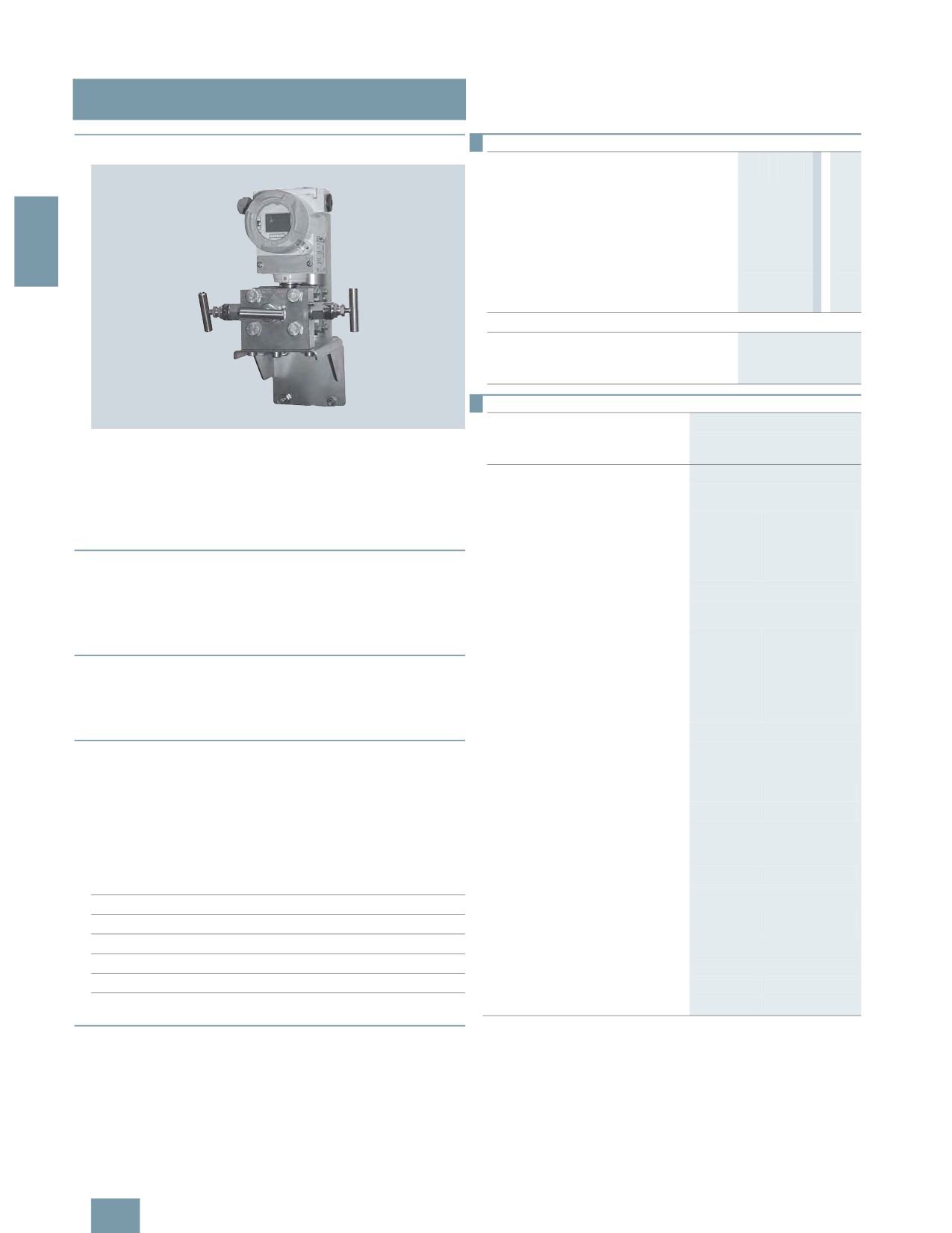
2-, 3- and 5-spindle valve manifolds
for installing in protective boxes
■Overview
Selection and Ordering data
Order No.
Valve manifolds DN 5 for mounting in
7MF9412 -77A
protective boxes
for liquids and gases
for flanging to pressure transmitters for
absolute and differential pressure
2
Material: stainless steel, mat. No: 1.4404/316L
max. working pressure 420 bar
(order accessory set with Order code),
without certificate
• 2-spindle valve manifold with rotatng sleeve
1B
G½
• 2-spindle valve manifold with flange
1C
connection
• 3-spindle valve manifold
1D
• 5-spindle valve manifold
1E
Accessories
Factory test certificate EN 10204-2.2
7MF9000-8AB
Material acceptance test certificate
7MF9000-8AD
The two-spindle, three-spindle and five-spindle valve manifolds
EN 10204-3.1
(7MF9412-1..) are used to shut off the differential pressure lines
and to check the transmitter zero.
Selection and Ordering data
Order code
Order No.
Further designs1)
The five-spindle valve manifold permits venting on the transmit-
ter side and checking of the transmitter characteristic.
Please add "-Z" to Order No. and
specify Order code.
These valve manifolds are preferentially used when mounting in
protective boxes. In addition, they can also be used for wall,
Accessory set to EN
frame or pipe mounting together with the mounting bracket.
(connection between valve manifold
and pressure transmitter)
Transmitters of the DS series can be operated and read from the
for valve manifold 7MF9412-1C.
front when using these valve manifolds.
2x screws 7/16-20 UNF x 2 inch to
F32
7MF9412-6CA
ASME B18.2.1; chromized steel
■Application
1x O-ring to DIN 3771,
20 x 2.65 - S - FPM90,
The valve manifolds DN 5 are designed for liquids and vapors
max. permissble 420 bar, 120 °C
and for installing in protective boxes.
2x screws 7/16-20 UNF x
F35
7MF9412-6DA
Each is available in a version for oxygen on request
2 inch to ASME B18.2.1; chromized
steel
1x gasket made of PTFE,
■Design
max. permissible 420 bar, 80 °C2)
All versions of the spindle manifolds have a process connection
for valve manifold 7MF9412-1D and
½-14 NPT.
-1E.
The connection for the pressure transmitter is always designed
4x screws 7/16-20 UNF x
F34
7MF9412-6GA
as a flange connection to EN 61518, Form A.
2 inch to ASME B18.2.1; chromized
steel
The 2-spindle and the 5-spindle valve manifold have in addition
2x O-rings to DIN 3771,
a vent and test connection ¼-18 NPT.
20 x 2.65 - S - FPM90,
max. permissble 420 bar, 120 °C2)
The valves have an external spindle thread.
4x screws 7/16-20 UNF x
F36
7MF9412-6HA
Materials used
2 inch to ASME B18.2.1; chromized
steel
Components
Material
Mat. No.
2x flat gaskets made of PTFE,
2)
max. permissible 420 bar, 80 °C
Housing
X 2 CrNiMo 17 13 2
1.4404/316L
Cones
X 6 CrNiMoTi 17 12 2
1.4571/316Ti
Spindles
X 2 CrNiMo 18 10
1.4404/316L
Head parts
X 5 CrNiMo 18 10
1.4401/316
Packings
PTFE
-
■Functions
Functions of all valve manifolds:
• Shutting off the differential pressure lines
• Checking the pressure transmitter zero
Additional functions of the 2-spindle and 5-spindle valve mani-
folds through the vent and test connection:
• Venting on the transmitter side
• Checking the pressure transmitter characteristic
2/216

SITRANS P measuring instruments for pressure
Fitttings - Shut-off valves for differential pressure transmitters
2-, 3- and 5-spindle valve manifolds
for installing in protective boxes
Selection and Ordering data
Order code
Order No.
■Accessories
Further designs1)
Accessory set for 2-, 3- and 5-spindle valve manifolds (Con-
Please add "-Z" to Order No. and
nection between manifold and transmitter)
specify Order code.
Accessory set to DIN
2-spindle valve manifold DN 5 with flange connection
(connection between valve manifold
• F32: 2 screws 7/16 20 UNF x 2 inch to ASME B 18.2.1,
2
and pressure transmitter)
1 O Ring (FPM90)
for valve manifold 7MF9412-1C.
• F35: 2 screws 7/16 20 UNF x 2 inch to ASME B 18.2.1,
2x screws M10x50 to DIN EN 24014;
F12
7MF9412-6AA
1 flat-gasket
chromized steel
• F12: 2 screws M10x50 to DIN EN 24014, 2 washers,
2x washers Ø 10.5 mm to DIN 125;
1 O-ring (FPM90)
1x O-ring to DIN 3771,
20 x 2.65 - S - FPM90, max. permiss-
• F15: 2 screws M10x50 toDIN EN 24014, 2 washers,
ble 420 bar, 120 °C2)
1 flat gasket
2x screws M10x50 to DIN EN 24014;
F15
7MF9412-6BA
3-spindle and 5-way valve manifold DN 5
chromized steel
2x washers Ø 10.5 mm to DIN 125;
• F34: 4 screws 7/16 20 UNF x 2 inch toASME B 18.2.1,
1x gasket made of PTFE,
2 O-rings (FPM90)
max. permissible 420 bar, 80 °C2)
• F36: 4 screws 7/16 20 UNF x 2 inch toASME B 18.2.1,
for valve manifold 7MF9412-1D and
2 flat-gaskets
-1E.
• F14: 4 screws M10x50 toDIN EN 24014, 4 washers,
4x screws M10x50 to DIN EN 24014;
F14
7MF9412-6EA
2 O-rings (FPM90)
chromized steel
4x washers Ø 10.5 mm to DIN 125;
• F16: 4 screws M10x50 toDIN EN 24014, 4 washers,
2x O-rings to DIN 3771,
2 flat-gaskets
20 x 2.65 - S - FPM90, max. permiss-
ble 420 bar, 120 °C2)
Washers Ø 10,5 to DIN 125
4x screws M10x50 to DIN EN 24014;
F16
7MF9412-6FA
Flat-gaskets made of PTFE, max. 420 bar, 80 °C
chromized steel
4x washers Ø 10.5 mm to DIN 125;
O-ring to DIN 3771, 20 x 2,65 - S - FPM90; max.420 bar, 120 °C
2x flat gaskets made of PTFE,
Note:
max. permissible 420 bar, 80 °C2)
Flange connections with M10 screws only permissible up to
Mounting bracket
PN 160!
required for wall mounting or for
securing to mounting rack, with bolts
Mounting bracket for wall mounting or for securing to
for mounting on valve manifold
mounting rack
• for valve manifolds 7MF9412-1B.
M14
7MF9006-6LA
With bolds for mounting on valve manifold
and -1C.
• M14: For 2-spindle valve manifold DN 5
• for valve manifold 7MF9412-1D.
M17
7MF9006-6NA
• M17: For 3-spindle valve manifold DN 5
• for valve manifold 7MF9412-1E.
M18
7MF9006-6PA
• M18: For 5-spindle valve manifold DN 5
Mounting clip
Mounting clips (2 off)
M16
2 off, to secure mounting bracket
7MF9006-6KA
to pipe
• M16: For securing the mounting brackets M14, M17 and M18
to pipe
Valve manifold 100 bar
suitable for oxygen
Valve manifold 100 bar, suitable for oxygen
• S12: For 2-spindle valve manifold DN 5
• for valve manifolds 7MF9412-1B.
S12
and -1C.
• S13: For 3-spindle valve manifold DN 5
• for valve manifold 7MF9412-1D.
S13
• S14: For 5-spindle valve manifold DN 5
• for valve manifold 7MF9412-1E.
S14
■Characteristic curves
1) When ordering accessory set or mounting together with the valve
manifolds, please use Order code; otherwise use Order No.
2) Flange connections with M10 screws only permissible up to PN 160!
F
0
%
0
F
D"
%; F
D"
%
0
D"
1
Permissible operating pressure as a function of the permissible operating
temperature
2/217

SITRANS P measuring instruments for pressure
Fitttings - Shut-off valves for differential pressure transmitters
2-, 3- and 5-spindle valve manifolds
for installing in protective boxes
■Dimensional drawings
;0
-8
2
?%#;
,7
8= >
,7
(
%7
77#<
,7
(
#8
0= >
>
1
#B
+= ?
; 7$4
1
(
&
C &
!
#
@
!
5
!
J 7= >
8 0= >
,7
3-spindle valve manifold DN 5 (7MF9412-1D..), dimensions in mm
(
#8
0= >
>
1
#
=
* = ? 70$ -8
$
9 :
" C
)
#J
7= >
;0
2-spindle valve manifold DN 5 (7MF9412-1B..) with rotating sleeve,
dimensions in mm
:
;
,7
"
J 7= >
8 0= >
,7
%7
(
7:
0
#
7
(
#8
0= >
>
1
#
"
B
+= ?
; 7$4
1
(
,7
(
" C
)
#J
7= >
C &
!
#
@
!
5
!
5-spindle valve manifold DN 5 (7MF9412-1E..), dimensions in mm
J 7= >
8 0= >
,7
(
#8
0= >
>
1
#
B
+= ?
; 7$4
1
(
" C
)
#J
7= >
C &
!
#
@
!
5
!
2-spindle valve manifold DN 5 (7MF9412-1C..), dimensions in mm
2/218

SITRANS P measuring instruments for pressure
Fitttings - Shut-off valves for differential pressure transmitters
2-, 3- and 5-spindle valve manifolds
for installing in protective boxes
M8
72
2
2.5
4x Ø11
55
2
100
1
&
110
//
1
5
Ø16
Ø26
&4
21
26.6
31.6
6.35
57.6
Mounting bracket (7MF9006-6PA)/(M18) for 5-spindle valve manifolds,
77.1
dimensions in mm
110
■Schematics
Mounting bracket (7MF9006-6LA)/(M14) for 2-spindle valve manifolds,
dimensions in mm
0
0
+
G
8
2-spindle valve manifold DN 5 (with rotating sleeve G½ or flange connec-
tion), connections
2
1
&
- .
3-spindle valve manifold DN 5, connections
1
*
*
&4
21
Mounting bracket (7MF9006-6NA)/(M17) for 3-spindle valve manifolds,
-
dimensions in mm
G
8
5-spindle valve manifold DN 5, connections
2/219
SITRANS P measuring instruments for pressure
Fitttings - Shut-off valves for differential pressure transmitters
3- and 5-spindle valve manifolds
for vertical angular differential pressure lines
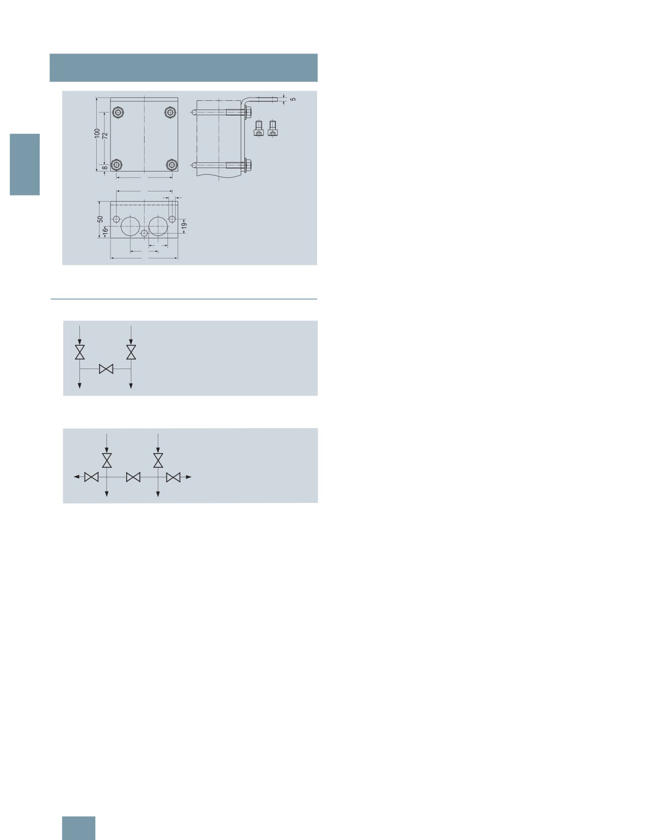
■Overview
Selection and Ordering data
Order No.
Valve manifolds for vertical differential
7MF9413 -77A
pressure lines
for liquids and gases
for flanging to pressure transmitters for abso-
lute and differential pressure
Material: stainless steel, mat. No: 1.4404/316L
2
max. working pressure 420 bar
(order accessory set with Order code),
without certificate
• 3-spindle valve manifold
1D
• 5-spindle valve manifold
1E
Accessories
Factory test certificate EN 10204-2.2
7MF9000-8AB
Material acceptance test certificate
7MF9000-8AD
EN 10204-3.1
Selection and Ordering data
Order code
Order No.
Further designs1)
These 3-spindle and 5-spindle valve manifolds 7MF9413-1..
Please add "-Z" to Order No. and
were developed specially for vertical differential pressure lines.
specify Order code.
Accessory set to EN
The valve manifolds are used to shut off the differential pressure
(connection between valve manifold
lines and to check the pressure transmitter zero.
and pressure transmitter)
The 5-spindle valve manifold permits venting on the transmitter
4x screws 7/16-20 UNF x
K36
7MF9411-5DB
side and checking of the pressure transmitter characteristic.
1¾ inch to ASME B18.2.1;
chromized steel
2x flat gaskets made of PTFE,
■ Benefits
max. permissible 420 bar, 80 °C
• For vertical differential pressure lines
Accessory set to DIN2)
• Max. operating pressure 420 bar
(connection between valve manifold
• Transmitters of the DS series can be operated and read from
and pressure transmitter)
the front.
4x screws M10x45 to DIN EN 24014;
K16
7MF9411-6BB
chromized steel
4x washers Ø 10.5 mm to DIN 125;
■Application
2x flat gaskets made of PTFE,
max. permissible 420 bar, 80 °C
The 3-spindle and 5-spindle valve manifolds for vertical differen-
Flange connection with M10 screws
tial pressure lines are for liquids and gases. The valve manifolds
only permissible up to PN 160.
are flanged on the pressure transmitter.
Mounting bracket
required for wall mounting or for
■Design
securing to mounting rack, with bolts
for mounting on valve manifold
All versions of the spindle valve manifolds have a process con-
nection ½-14 NPT.
• for valve manifold 7MF9413-1D.
M17
7MF9006-6NA
The connection for the pressure transmitter is always designed
• for valve manifold 7MF9413-1E.
M18
7MF9006-6PA
as a flange connection to EN 61518, form B .
required for mounting on 2" stand-
pipe, with bolts for mounting on
The 2-spindle and the 5-spindle valve manifold have in addition
valve manifold
a vent and test connection ¼-18 NPT.
• for valve manifold 7MF9413-1D.
M19
7MF9006-6QA
Materials used:
Mounting clip
Component
Material
Mat. No.
2 off, to secure mounting bracket
M16
7MF9006-6KA
Housing
X 2 CrNiMo 17 13 2
1.4404/316L
to pipe
Cones
X 6 CrNiMoTi 17 12 2
1.4571/316Ti
Valve manifold 100 bar
Spindles
X 2 CrNiMo 18 10
1.4404/316L
suitable for oxygen
Head parts
X 5 CrNiMo 18 10
1.4401/316
• for valve manifold 7MF9413-1D.
S13
Packings
PTFE
-
• for valve manifold 7MF9413-1E.
S14
1) When ordering accessory set or mounting together with the multiway cock,
■Function
please use Order code; otherwise use Order No.
2) Flange connections to DIN 19213 only permissible up to 160!
Functions of all valve manifolds:
• Shutting off the differential pressure lines
• Checking the pressure transmitter zero
Additional functions of the 2-spindle and 5-spindle valve mani-
folds through the vent and test connection:
• Venting on the transmitter side
• Checking the pressure transmitter characteristic
2/220

SITRANS P measuring instruments for pressure
Fitttings - Shut-off valves for differential pressure transmitters
3- and 5-spindle valve manifolds
for vertical angular differential pressure lines
■Accessories
Accessory set (connection between manifold and
;0
6
transmitter)
• K36: 4 screws 7/16-20 UNF x 1¾ inch to ASME B18.2.1, 2 flat
gaskets
2
• K16: 4 screws M10x45 to DIN EN 24014, 4 washers, 2 flat
gaskets
Washers Ø 10.5 to DIN 125
,7
8= >
J= >
%7
"
:?
% $:;
Flat gaskets made of PTFE, max. 420 bar, 80 °C
;
(
Note: Flange connection with M10 screws only permissible up to
%0
PN 160!
0
Mounting bracket for wall mounting or for securing to
mounting rack
5-spindle valve manifold 7MF9413-1E. for vertical differential pressure
With bolts for mounting on valve manifold
lines, dimensions in mm
• M17: For 3-spindle valve manifold
• M18: For 5-spindle valve manifold
Mounting bracket for mounting on 2" standpipe
With bolts for mounting on valve manifold
• M19: For 3-spindle valve manifold
Mounting clips (2 off)
2
For securing the mounting brackets M17, M18 and M19 to pipe
1
&
Valve manifold 100 bar, suitable for oxygen
• For 3-spindle valve manifold
• For 5-spindle valve manifold
■Characteristic curves
1
F
0
&4
21
%
0
F
D"
Mounting bracket (7MF9006-6NA)/(M17) for 3-spindle valve manifolds,
%; F
D"
dimensions in mm
%
0
D"
1
Permissible operating pressure as a function of the permissible operating
temperature
2
■Dimensional drawings
1
&
//
;0
6
1
5
&4
,7
21
%7
)
= >
:?
(
% $:;
7<
<:
Mounting bracket (7MF9006-6PA)/(M18) for 5-spindle valve manifolds,
dimensions in mm
3-spindle valve manifold 7MF9413-1D. for vertical differential pressure
lines, dimensions in mm
2/221
SITRANS P measuring instruments for pressure
Fitttings - Shut-off valves for differential pressure transmitters
3- and 5-spindle valve manifolds
for vertical angular differential pressure lines
2
2
21
5
1
&4
5
Mounting bracket (7MF9006-6QA)/(M19) for 3-spindle and 5-spindle
valve manifolds, dimensions in mm
■Schematics
- .
3-spindle valve manifold for vertical differential pressure lines, connec-
tions
-
G
8
8)
47 -
5-spindle valve manifold for vertical differential pressure lines, connec-
tions
2/222

SITRANS P measuring instruments for pressure
Fitttings - Shut-off valves for differential pressure transmitters
Low-pressure multiway cock
■Overview
Selection and Ordering data
Order No.
Low-pressure multiway cock
for liquids and gases, for flanging to pressure
transmitters, max. working pressure 25 bar,
max. working temperature 60 °C
(up to 80 °C for a short time), weight 1.75 kg
(without accessory set)
2
Test connections
2x sealing screws G3/8
7MF9004-4CA
2x quick-release couplings
7MF9004-4DA
Selection and Ordering data
Order code
Order No.
Further designs1)
Please add "-Z" to Order No. and
specify Order code.
Accessory set to EN
(required for flanging, weight 0.2 kg)
4x screws 7/16-20 UNF x 1 inch
L31
7MF9004-5CC
to ASME B18.2.1; chromized steel
The low-pressure multiway cock 7MF9004-4CA/-4DA can be
2x gaskets made of PTFE, max.
flanged to pressure transmitters for differential pressure.
permissible temperature 80 °C
Accessory set to DIN
■ Benefits
(required for flanging, weight 0.2 kg)
• Robust design
4x screws M10x25 to DIN EN 24017;
• For liquids and gases
chromized steel
4x washers Ø 10.5 mm to DIN 125;
• One-hand operation
2x gaskets made of PTFE, max.
permissible temperature 80 °C
■Design
• Standard design
L11
7MF9004-6AD
The multiway cock has 2 process connections and 2 test con-
• Version for oxygen
L15
7MF9004-6AE
nections, which are available in 2 versions (with sealing screws
Multiway cock in oil-free and
G3/8 or quick-release couplings). The housing is made of hot-
grease-free design
pressed brass CuZn39Pb3, CW 614N. Test connections with
BAM-tested lubricant, gasket
S11
sealing screws or with self-sealing quick-release couplings.
suitable for oxygen
Note: An accessory set is always required for flanging of the
Mounting bracket
multiway cock to a differential pressure transmitter.
required for wall mounting or for
M13
7MF9004-6AA
securing on rack (72 mm grid),
made of electrogalvanized sheet-
■Function
steel, weight 0.85 kg
• Shutting off the differential pressure lines
1) When ordering accessory set or mounting together with the multiway cock,
• Testing the pressure transmitter zero
please use Order code; otherwise use Order No.
• Testing the pressure transmitter characteristic
■Accessories
Accessory set for low-pressure multiway cock
• L11: 4 screws M10x25 to DIN EN 24017, 4 washers, 2 flat gas-
kets
• L15 (suitable for oxygen): 4 screws M10x25 to DIN EN 24017,
4 washers, 2 flat gaskets
• L31: 4 screws 7/16-20 UNF x 1 inch, 2 flat gaskets
Washers Ø 10.5 to DIN 125
Cock positions; the symbols are printed on the cock
Flat gaskets made of PTFE, max. permissible temperature 80 °C
Multiway cock in oil-free and grease-free design
• S11: BAM-tested lubricant, gasket suitable for oxygen
Mounting brackets
• M13: Required for wall mounting or for securing on rack
(72 mm grid); made of electrogalvanized sheet-steel
2/223

SITRANS P measuring instruments for pressure
Fitttings - Shut-off valves for differential pressure transmitters
Low-pressure multiway cock
■Options
■Characteristic curves
Test connections
• 2 sealing screws G3/8
• 2 quick-release couplings
2
Low-pressure multiway cock, permissible operating pressure as a func-
tion of the permissible operating temperature
■Dimensional drawings
Low-pressure multiway cock 7MF9004-4CA/-4DA for direct flanging to pressure transmitters for differential pressure, dimensions in mm
)
1
5
2
)
1
Mounting bracket 7MF9004-6AA (M13), dimensions in mm
2/224

SITRANS P measuring instruments for pressure
Fittings - Accessories
Oval flange
■Overview
Selection and Ordering data
Order No.
Oval flange
with female thread ½-14 NPT, max. working
pressure 420 bar, flange connection to
DIN EN 61518, form A
Material
2
P250GH, mat. No.: 1.0460
7MF9408-2CE
X 2 CrNiMo 17 13 2, mat. No. 1.4404/316L
7MF9408-2CL
Selection and Ordering data
Order code
Order No.
Further designs
Please add "-Z" to Order No. and
specify Order code.
Accessory set to EN1)
2x screws 7/16-20 UNF x
E36
7MF9408-5DA
1½ inch to ASME B 18.2.3;
chromized steel
1x flat gasket made of PTFE,
max. permissible 420 bar, 80 °C
The oval flange 7MF9408-2C. for pressure transmitters for abso-
2x screws 7/16-20 UNF x
E34
7MF9408-5CA
lute pressure and differential pressure has a ½-14 NPT female
1½ inch to ASME B 18.2.3;
thread and is designed for max. operating pressure 400 bar.
chromized steel
1x O-ring to DIN 3771,
20 x 2.65 - S - FPM90,
■Accessories
max. permissble 420 bar, 120 °C
• E34: 2 screws 7/16-20 UNF x 1½ inch to ASME B18.3,
Accessory set to DIN1)
1 O-ring (FPM 90)
2x screws M10x40 to
E13
7MF9408-6AA
• E13: 2 screws M10x40 to DIN EN 4762, 2 washers,
DIN EN ISO 4762; chromized steel
1 O-ring (FPM 90)
2x washers Ø 10.5 mm to DIN 125;
• E36: 2 screws 7/16-20 UNF x 1½ inch to ASME B18.2.1,
1x O-ring to DIN 3771,
20 x 2.65 - S - FPM90,
1 flat gasket
max. permissble 420 bar, 120 °C2)
• E16: 2 screws M10x40 to DIN EN ISO 4762, 2 washers,
2x screws M10x40 to
E16
7MF9408-6BA
1 flat gasket
DIN EN ISO 4762; chromized steel
Washers Ø 10.5 to DIN 125
2x washers Ø 10.5 mm to DIN 125;
1x flat gasket made of PTFE,
Flat gaskets made of PTFE, max. 420 bar, 80 °C
max. permissible 420 bar, 80 °C2)
O-ring to DIN 3771, 20 x 2.65 - S - FPM90, max. 420 bar, 120 °C
1) When ordering accessory set together with the oval flange, please
use Order code; otherwise use Order No.
Note: M10 screws only permissible up to PN 160!
2) Flange connections with M10 screws only permissible up to PN 160!
■Dimensional drawings
Oval flange 7MF9408-2C., dimensions in mm
2/225

SITRANS P measuring instruments for pressure
Fittings - Accessories
Adapters, connection glands
■Overview
■Dimensional drawings
Adapters enable e.g. a transition from medium connections with
NPT thread to shut-off valves to DIN 16270 ... 16272 or pipes in
conjunction with a connection gland (e.g. 7MF9008).
2
■Design
The connection pieces are made of X 6 CrNiMoTi 17 12 2, mat.
No. 1.4571 and available in 3 versions
• Thread ¼-18 NPT and connection shank G½ to DIN EN 837-1
Connection piece with thread ¼-18 NPT and connection shank G½
• Thread ½-14 NPT and connection shank G½ to DIN EN 837-1
7MF9001-1AA, dimensions in mm
• Thread ½-14 NPT and thread ½-14 NPT
Selection and Ordering data
Order No.
Adapter
(weight 0.2 kg)
with thread ¼-18 NPT - G½
7MF9001-1AA
with thread ½-14 NPT - G½
7MF9001-1CA
with thread ½-14 NPT - ½-14 NPT
7MF9001-1DA
with thread ½-14 NPT - M20 x 1.5
7MF9001-1EA
Connection piece with thread ½--14 NPT and connection shank G½
7MF9001-1CA, dimensions in mm
Connection piece with thread ½-14 NPT and thread ½-14 NPT
7MF9001-1DA, dimensions in mm
Connection piece with thread ½-14 NPT and thread M20 x 1.5
7MF9001-1EA, dimensions in mm
■Overview
■Dimensional drawings
Connection glands to connect medium or differential pressure
lines to collars G½ to DIN EN 837-1
• For rated pressures up to PN 630
• For oxygen only up to PN 250
Selection and Ordering data
Order No.
Connection screwed gland
for pipelines
(weight 0.2 kg)
Material
Design
11SMn30
Standard
7MF9008-1GA
Connection gland 7MF9008-1G., dimensions in mm
(mat. No. 1.0715)
X 6 CrNiMoTi 17 12 2
Standard
7MF9008-1GB
(mat. No. 1.4571/316Ti)
X 6 CrNiMoTi 17 12 2
Grease-free
7MF9008-1GC
(mat. No. 1.4571/316Ti)
2/226

SITRANS P measuring instruments for pressure
Fittings - Accessories
Connection parts G 1/2
■Overview
■Dimensional drawings
Connection parts G½ for pressure gages and shut-off fittings are
-
available in 3 versions:
6:
• Nipple connection
• Clamping sleeve
2
• Collar connection piece
9 :
Selection and Ordering data
Order No.
6
Adapters G½
for pressure gages and shut-off fittings
Nipple connection (G) M56340-A0001 to -A0003, dimensions in mm
Nipple connection
,
@
$;
G½ to DIN 16284 (union nut with nipple and
6:
gasket); max. working pressure 400 bar;
weight 0.1 kg;
connection: G½ to DIN EN 837-1;
Female thread G½
Material
Mat. No.
9 :
CuZn39Pb3
CW 614N
M56340-A0001
6 0
Union nut
M56340-A0002
9 SMn 28 k
1.0715
Nipple:
Nipple connection (M20 x 1.5) M56340-A0008, dimensions in mm
RSt 37-2
1.0037
Union nut
M56340-A0003
X 8 CrNiS 18 9
1.4305
Nipple:
X 6 CrNiMoTi 17 12 2
1.4571/316Ti
Nipple connection
M20 x 1.5 to DIN 16284 (union nut with nipple
Clamping sleeve M56340-A0004/-A0005, dimensions in mm
and gasket); max. working pressure 400 bar;
weight 0.1 kg;
connection: G½ to DIN EN 837-1;
Female thread G½
Material
Mat. No.
Union nut
M56340-A0008
X 8 CrNiS 18 9
1.4305
Nipple:
X 6 CrNiMoTi 17 12 2
1.4571/316Ti
Clamping sleeve
Collar connection piece M56340-A0006/-A0007, dimensions in mm
G½ to DIN 16283; max. working pressure
400 bar; weight 0.1 kg;
Connections: G½ to DIN EN 837-1;
Female thread: G½ right-hand G½ left-hand
Material
Mat. No.
CuZn39Pb3
CW614N
M56340-A0004
9 SMn 28 k
1.0715
M56340-A0005
Collar-adapter
max. working pressure; weight 0.1 kg;
Connections: G½ to DIN EN 837-1;
Male thread: G½, G½
Material
Mat. No.
CuZn39Pb3
CW614N
M56340-A0006
9 SMn 28 k
1.0715
M56340-A0007
2/227

SITRANS P measuring instruments for pressure
Fittings - Accessories
Water traps, Sealing rings to EN 837-1
■Overview
■Overview
Water traps protect pressure gages and shut-off fittings from
The sealing rings to EN 837-1 are required to seal measuring in-
heating up (e.g. by steam) by the water column produced by the
struments for pressure with the process connection G½B.
water trap.
The max. working temperature is 120 °C at 160 bar, 300 °C at
■Dimensional drawings
2
80 bar or 400 °C at 63 bar. If the temperature of the measured
medium is higher, a sufficiently long line has to be connected up-
stream of the trap to enable heat dissipation.
■Design
The water traps are available in U shape (type B) or circular
shape (type D) to DIN 16282. They have a weld-on end
Ø 20 mm × 2.6 mm on the measurement side. The connection
on the device side is a clamping sleeve G½ to DIN 16283.
The water traps are made of steel (P250GH) or stainless steel
Sealing ring 7MF9007-7A. to EN 837-1, dimensions in mm
(X 6 CrNiMoTi 17 12 2)
Water traps are designed as standard for max. operating tem-
Selection and Ordering data
Order No.
perature 120 °C at max. operating pressure 160 bar (300 °C at
80 bar, 400 °C at 63 bar). Water traps for higher operating pres-
Sealing ring to EN 837-1 for thread G½
made of
sures and temperatures are available on request.
(packing unit 100 pcs)
• copper
F)
7MF9007-7AA
Selection and Ordering data
Order No.
• soft iron
F)
7MF9007-7AB
Water traps
• stainless steel, mat.-No. 1.4571
F)
7MF9007-7AC
for pressure gages and pressure transmitters,
max. working temperature 120 °C,
• PTFE
F)
7MF9007-7AD
max. working pressure 160 bar (or 400 °C
and 104 bar), weight 0.7 kg
F) Subject to export regulations AL: 9I999, ECCN: N.
Water trap B to DIN 16282
Material
Mat. No.
P235GH
1.0345
M56340-A0043
X 6 CrNiMoTi 17 12 2
1.4571/316Ti
M56340-A0061
Water trap D to DIN 16282
Material
Mat. No.
P235GH
1.0345
M56340-A0045
X 6 CrNiMoTi 17 12 2
1.4571/316Ti
M56340-A0063
■Dimensional drawings
Water traps, type B, M56340-A0043/-A0061, dimensions in mm
Water traps, type D, M56340-A0045/-A0063, dimensions in mm
2/228

SITRANS P measuring instruments for pressure
Fittings - Accessories
Pressure surge reducers
■Overview
The pressure surge reducer protects the pressure gage against
damage, premature wear and tear and inaccurate/fluctuating in-
dications.
■Application
2
The pressure reducer is used when pulsations occur in the mea-
sured medium (e.g. in slow-running vapor engines, piston
pumps and compressors), or if drastic fluctuations are likely to
occur in the measured medium (e.g. in hydraulic presses and
tensile testing machines).
■Design
• Enclosure made of brass or stainless steel
• Adjustable nozzle
• Sleeve for connection to the measuring instrument
• Pin for connection to supply lead
Selection and Ordering data
Order No.
Pressure surge reducer
Weight approx. 0,21 kg
Material
Full-scale value
Weight approx.
in kg
Brass
250 bar
0.21
M56340-A54
Stainless
600 bar
0.21
M56340-A59
steel
■Dimensional drawings
*®
6OHHYH IRU FRQQHFWLRQ
WR WKH SUHVVXUH GLVSOD\
3LQ IRU FRQQHFWLRQ
WR VXSSO\ OHDG
*®
Pressure surge reducer, dimensions in mm
2/229

SITRANS P measuring instruments for pressure
Fittings - Accessories
Primary shut-off valves
■Overview
■Dimensional drawings
Primary shut-off valves are available in the following versions:
• For non-corrosive liquids, gases and vapors
67
• For corrosive liquids and gases
2
• Grease-free for oxygen
The shut-off valves are available in various materials and with
various connections (see Selection and Ordering data)
■Characteristic curves
F
;
0
-8
-8
<
%
"
*
+
Shut-off valve 7MF9017-1A., dimensions in mm
(
67
%
0
;
? D"
1
5
44
& &
:,B<
:
##
Shut-off valve 7MF9017-1.., permissible working pressure as a function
of the permissible working temperature
F
F
;
;
-8
,
@ $;
<
0
0
Shut-off valve 7MF9017-1B. and -2B., dimensions in mm
%
%
/
-
2
67
B
W
%
0
D"
D"
1
5
44
& &
:,B<
:
##
5
44
& &
:,B<
: %##
Shut-off valve 7MF9017-2.. and -3.., permissible working pressure as a
function of the permissible working temperature
,
@ $;
,
@ $;
<
$,
@ $;%
$,
@ $;%
Shut-off valves 7MF9017-1C., -1D. and -2C., dimensions in mm
2/230

SITRANS P measuring instruments for pressure
Fittings - Accessories
Primary shut-off valves
Ø A x b
7MF9017-
6
14 mm x 2.5 mm
1F. and 1G.
21.3 mm x 6.3 mm
1H. and 2H.
24 mm x 7.1 mm
1J., 1K. and 2J.
2
$;
;
0$;
?;
%
Shut-off valves 7MF9017-, dimensions in mm
Selection and Ordering data
Primary shut-off valves, without certificate
Max.
Charac- Material
Mat. No. Spindle
Connections
Approx.
Order No.
working
teristic1)
thread
weight kg
pressure
Shut-off valve for non-aggressive liquids, gases and vapors
7MF9017 - 17A
160 bar A
P250GH
1.0460
Internal
Threaded socket G½ form R, DIN 19207
0.8
A
160 bar A
P250GH
1.0460
Internal
Threaded socket G½ form R, DIN 19207
0.8
B
DIN 19207 and pipe union
with ferrule for pipe ∅ 12 mm, S series
400 bar C
P250GH
1.0460
Internal
Pipe union with ferrule
1
C
for pipe ∅ 12 mm, S series
400 bar C
P250GH
1.0460
Internal
Pipe union with ferrule
1
D
for pipe ∅ 14 mm, S series
500 bar D
16 Mo 3
1.5415
External
Welding sleeves ∅ 14 mm × 2.5 mm
1.6
F
500 bar E
11 CrMo 9 10
1.7383
External
Welding sleeves ∅ 14 mm × 2.5 mm
1.6
G
500 bar D
16 Mo 3
1.5415
External
Welding sleeves ∅ 21.3 mm × 6.3 mm
1.6
H
and ∅ 14 mm × 2.5 mm
500 bar D
16 Mo 3
1.5415
External
Welding sleeves ∅ 24 mm × 7.1 mm
1.6
J
and ∅ 14 mm × 2.5 mm
500 bar E
11 CrMo 9 10
1.7383
External
Welding sleeves ∅ 24 mm × 7.1 mm
1.6
K
and ∅ 14 mm × 2.5 mm
Shut-off valve for aggressive liquids and gases
7MF9017 - 27A
160 bar F
X 6 CrNiMoTi 17 12 2
1.4571/
Internal
Threaded socket G½ form R, DIN 19207
0.8
B
316Ti
DIN 19207 and pipe union
with ferrule for pipe ∅ 12 mm, S series
400 bar G
X 6 CrNiMoTi 17 12 2
1.4571/
Internal
Pipe union with ferrule
1
C
316Ti
for pipe ∅ 12 mm, S series
400 bar H
X 6 CrNiMoTi 17 12 2
1.4571/
External
Welding sleeves ∅ 21.3 mm × 6.3 mm
1.6
H
316Ti
and ∅ 14 mm × 2.5 mm
400 bar H
X 6 CrNiMoTi 17 12 2
1.4571/
External
Welding sleeves ∅ 24 mm × 7.1 mm
1.6
J
316Ti
and ∅ 14 mm × 2.5 mm
Accessories
Factory test certificate EN 10204-2.2
7MF9000-8AB
Material acceptance test certificate EN 10204-3.1
7MF9000-8AD
1) See Figure "Permissible working pressure as a function of the permissible working temperature"
2/231
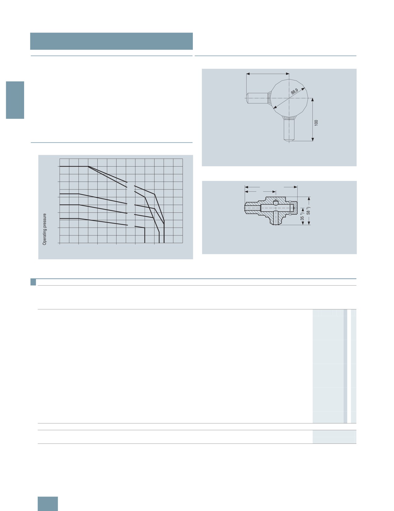
SITRANS P measuring instruments for pressure
Fittings - Accessories
Compensation vessels
■Overview
■Dimensional drawings
The compensation vessels prevent the level difference which oc-
curs with pressure changes in the pressure lines and which fal-
sifies the measurement.
According to DIN 19211, the temperature in the compensation
2
vessel must be assumed to be 50 K less than the steam temper-
ature in the pipe when calculating the wall thicknesses. This is
because the temperature in the compensation vessel during op-
eration can only rise up to the saturated steam temperature.
A material acceptance test certificate A to EN 10204-3.1 is avail-
able for the materials from which the compensation vessels are
made.
■Characteristic curves
! ""#
$
%
+
&
&
! ""#
$
%
/
Compensation vessel 7MF9015-1.., dimensions in mm
)
@#
?;
&
&
&
! ""#
$
%
! ""#
$
%
&
)
/
1
D
%
$$ '
!
( )
+
,
Compensation vessel 7MF9015-5.., dimensions in mm
Permissible operating pressure as a function of the permissible operating
temperature
Selection and Ordering data
Compensation vessel, without certificate
Max.
Characteristic1)Material
Mat. No. Connections
Approx.
Approx.
Order No.
working
contents
weight
Input
Output
pressure
cm³
kg
7MF9015 -77A
160 bar A
16 Mo 3
1.5415
Threaded socket G½,
Threaded socket G½,
250
0.8
1A
form R, DIN 19207
form V, DIN 19207
250 bar B
16 Mo 3
1.5415
Welding sleeve
Welding sleeve
250
0.8
1B
∅ 21 mm × 6.3 mm
∅ 21.3 mm × 6.3 mm
250 bar B
16 Mo 3
1.5415
Welding sleeve
Welding sleeve
250
1
1C
∅ 24 mm × 7.1 mm
∅ 24 mm × 7.1 mm
250 bar C
11 CrMo 9 10
1.7383
Welding sleeve
Welding sleeve
250
1
1D
∅ 24 mm × 7.1 mm
∅ 24 mm × 7.1 mm
250 bar B
16 Mo 3
1.5415
Welding sleeve
Welding sleeve
250
0.7
1E
∅ 33.7 mm × 4.5 mm
∅ 24 mm × 7.1 mm
160 bar A
16 Mo 3
1.5415
Threaded socket G½,
Threaded socket G½,
20
1.6
5A
form R, DIN 19207
form V, DIN 19207
500 bar D
16 Mo 3
1.5415
Welding sleeve
Welding sleeve
20
1.6
5B
∅ 21 mm × 6.3 mm
∅ 21.3 mm × 6.3 mm
500 bar D
16 Mo 3
1.5415
Welding sleeve
Welding sleeve
20
1.6
5C
∅ 24 mm × 7.1 mm
∅ 24 mm × 7.1 mm
500 bar E
11 CrMo 9 10
1.7383
Welding sleeve
Welding sleeve
20
1.6
5D
∅ 24 mm × 7.1 mm
∅ 24 mm × 7.1 mm
Accessories
Factory test certificate EN 10204-2.2
7MF9000-8AB
Material acceptance test certificate EN 10204-3.1
7MF9000-8AD
1) See Figure "Permissible working pressure as a function of the permissible working temperature"
2/232
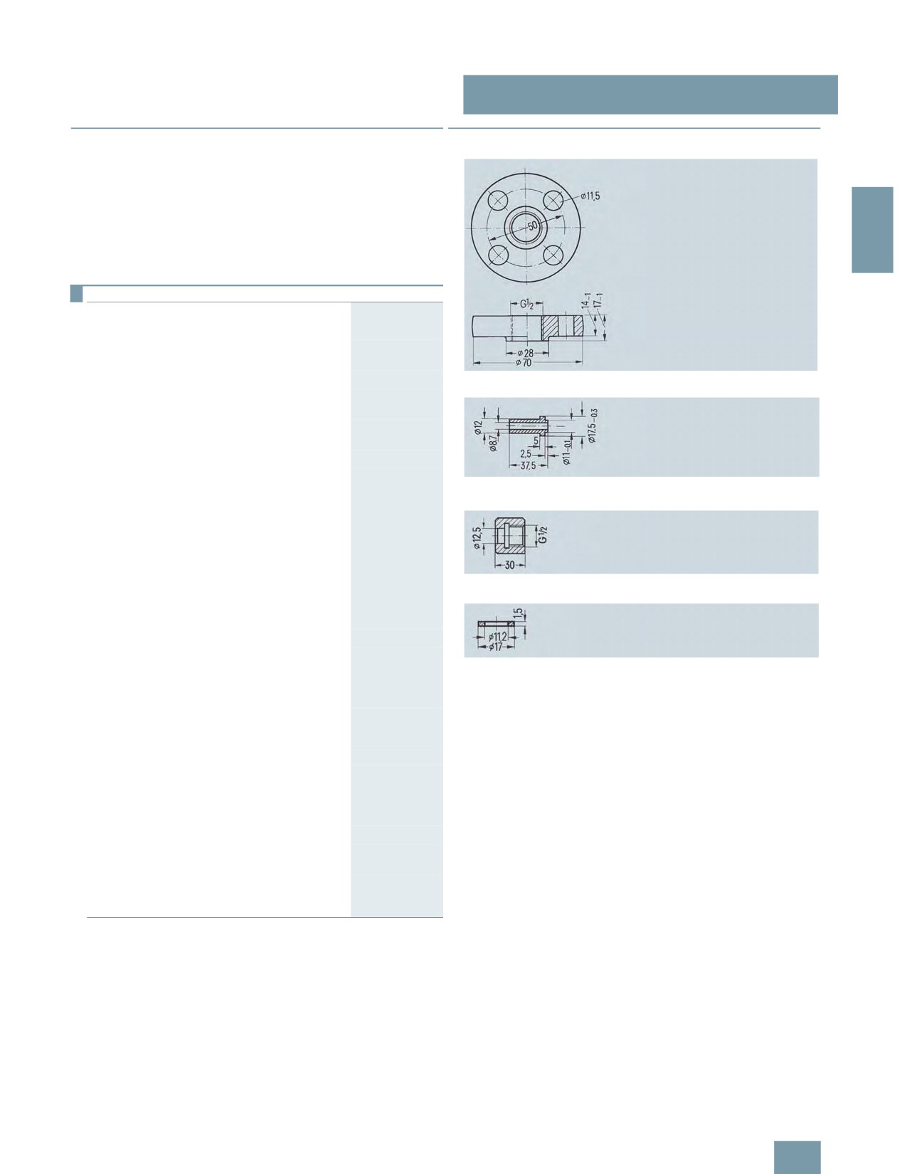
SITRANS P measuring instruments for pressure
Fittings - Accessories
Connection parts
■Overview
■Dimensional drawings
Connection parts are available in the following versions:
• Threaded flange pair G½ with stainless steel gasket
• Nipple G½ form V to DIN 19207
• Union nut G½ made of C 35 to DIN 16284
2
• Gasket B½ (grooved) to DIN 19207
All connection parts are also available grease-free for oxygen.
Selection and Ordering data
Order No.
Threaded flange pair G½
• with stainless steel gasket
7MF9007-4CA
• grease-free for oxygen, with stainless
7MF9007-4DA
steel gasket
Scope of delivery:
Threaded flange 7MF9007-4CA/-4DA, dimensions in mm
2x threaded flanges G½ to DIN 19207; material:
P250GH (mat. No. 1.0460)
4x hexagon screws M10x45 to DIN EN 24014;
Material: C35E (mat. No. 1.1181)
4x hexagon screws M10x50 to DIN EN 24032
1x gasket G½ (7MF9007-6BA) grooved,
to DIN 19207;
Nipple G½ 7MF9007-4KA/-4LA, dimensions in mm
Material: X 6 CrNiMoTi 17 12 2
(mat. No. 14571/316Ti)
Only for 7MF9007-4CA!
1x gasket G½ (7MF9k007-6CA), grease-free for
oxygen, grooved, to DIN 19207;
Material: X 6 CrNiMoTi 17 12 2
(mat. No. 14571/316Ti)
Union nut G½ 7MF9007-4MA/-4NA, dimensions in mm
Only for 7MF9007-4DA!
Nipple G½
to DIN 19207
• Material: 16 Mo 3 (mat. No. 1.5415)
7MF9007-4KA
• grease-free for oxygen,
7MF9007-4LA
Gasket 7MF9007-6BA/-6CA, dimensions in mm
Material: X 6 CrNiMoTi 17 12 2
(mat. No. 1.4571/316Ti)
Union nut G½
7
to DIN 16284
• Material: C35E (mat. No. 1.1181)
7MF9007-4MA
• grease-free for oxygen,
7MF9007-4NA
Material: X 6 CrNiMoTi 17 12 2
(mat. No. 1.4571/316Ti)
Gasket G½
to DIN 19207, grooved
• Material: X 6 CrNiMoTi 17 12 2
F)
7MF9007-6BA
(mat. No. 1.4571/316Ti)
• grease-free for oxygen,
F)
7MF9007-6CA
Material: X 6 CrNiMoTi 17 12 2
(mat. No. 1.4571/316Ti)
F) Subject to export regulations AL: 9I999, ECCN: N.
2/233
SITRANS P measuring instruments for pressure
2
2/234