Siemens SITRANS P. Operating Instructions (2019) - page 11
SITRANS P measuring instruments for pressure
Transmitters for gage, absolute and differential pressure, flow and level
DS III series
for differential pressure and flow
;
$
#?%
00
$;#?:%
@# %
$
#
%
$%#<0%
;
?
$
#
%
2
%
"
0
?< $ #:%
"
;
<
$%#?%"
<
7
:
;
$
#
;%
:
$
#7%%
; $0# %
?7
$
#:%
$0#:%
#J
7 = > $+= ? ; 7%
3
%
+
#
!
!,
@ $;0%$
!
!8 0= >
%% 0%
B
,
0
>
1
!
;
+
! $!
!
$
&
54
&
5
!
%
?
&
& &
3
:
,
F
3
$
%
7
5& &
$
%
%
(
@#
11
$
#:<
5%
5
!
5
!!
<
& N
4
F
3
$
4
@
4
$
5
5
!
%
%
<
11
$%#?
5% 4
1 11!
1
5
!
&
4
H
!1
1
$
!
!%
%%
=
5
4
K
@
4
K
&
4
1
1
$
44 @ 2
%
0%
=
5
4
KB, " (K
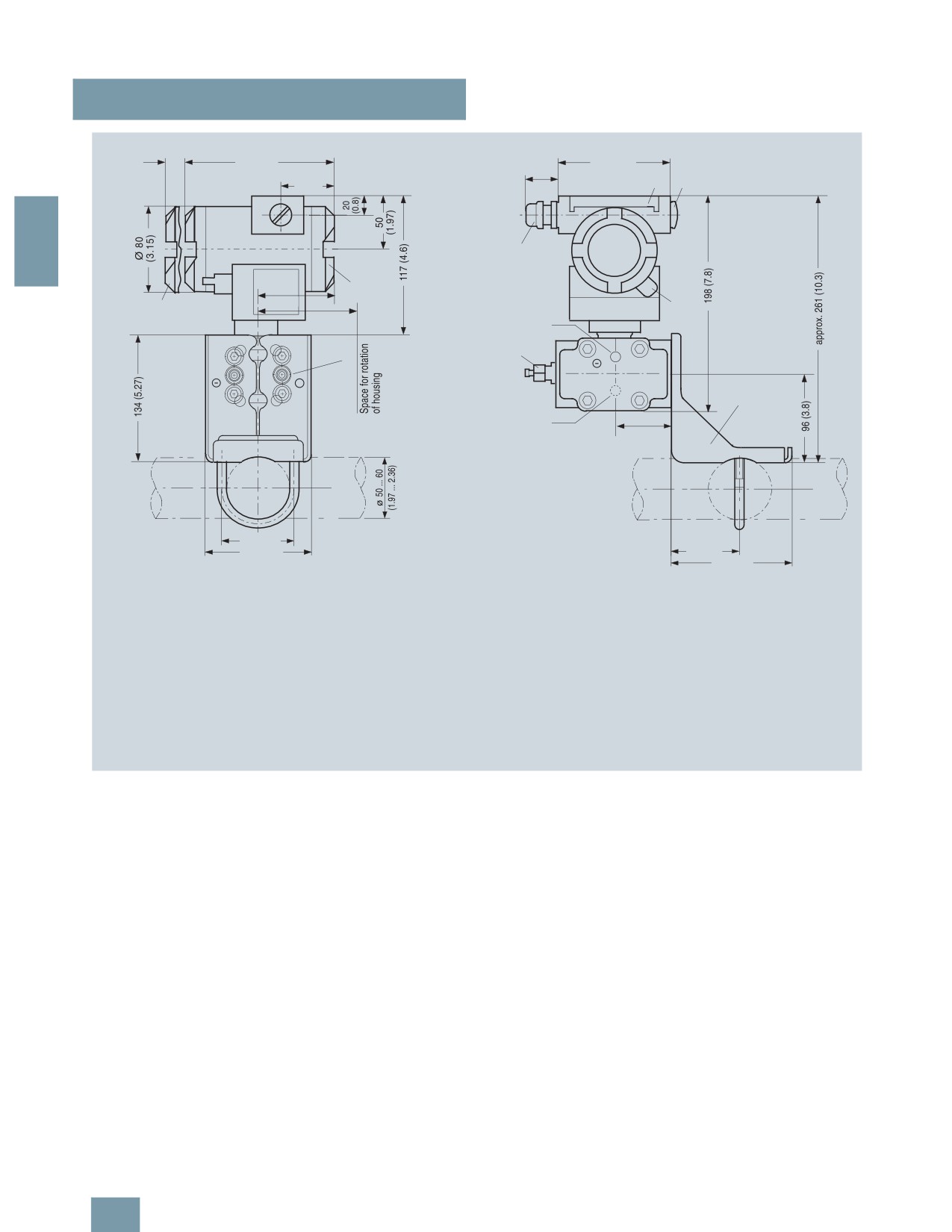
SITRANS P pressure transmitters, DS III PA and FF series for differential pressure and flow, dimensions in mm (inch)
2/120

SITRANS P measuring instruments for pressure
Transmitters for gage, absolute and differential pressure, flow and level
DS III series
for differential pressure and flow
;
00
$;#?:%
$%#<0%
$
#?%
@# %
$
#
7%7%
;
@# <? $%#:7%
?
:0
$
#<%
$
#
%
2
%
%
0 %
<
; %
<
$%#?%0%
7
7
?: $ #?0%;%
@# 70$? $%#%%%
#J
7 = > $+= ? ; 7%
3
%
+
#
!
!
%$; $
!
%
% %%$
!
!,
@ $;%%$
!
!8 0= >
% %%
%
(
@#
11
$
#:<
5%
5
!
5
1
2
:*) 2
7
0
>
1
!
%
=
5
4
K
@
4
K
;
+
! $!
!
$
&
54
&
5
!
%
%%
=
5
4
KB, " ( L
@ MK
?
&
& &
3
0%
<
11
$%#?
5% 4
1 11!
1
5
!
:
,
F
3
$
%
;%
:0 11
$
#<
5% 4
=
0
$,9
? <
%
7
5& &
$
%
?%
<
11
$%#?
5% 4
=
0
$,9
? <
%
<
&
4
F
3
$
4
4
:%
< 11
$7#?
5% 4
=
0
$,9
? <
%
K+@
4
K$
5
5
!
%
7%
0; 11
$
#7
5% 4
%$;
5
!
SITRANS P pressure transmitters, DS III HART series for differential pressure and flow, with process covers for vertical differential pressure lines, option
„H03“, dimensions in mm (inch)
2/121

SITRANS P measuring instruments for pressure
Transmitters for gage, absolute and differential pressure, flow and level
DS III series
for differential pressure and flow
;
00
$;#?:%
$%#<0%
$
#?%
@%
$
#
7%?%
;
?
:0
$
#<%
$
#
%
2
%
0 %
<
; %
<
$%#?%0%
7
7
;%
?: $ #?0%
@#
70$? $%#%%%
J 7 = > $+= ? ; 7%
%
(
@#
11
$
#:<
5%
5
!
5
!!
3
%
=
5
K
@
4
K
%
+
#
%%
=
5
KB, " ( L
@ MK
!
!,
@ #;%%$
0%
<
11
$%#?
5% 4
1 11!
1
!
!8 0= >
5
!
% %%
B
,
;%
:0 11
$
#<
5% 4
=
0
$,9
? <
%
0
> 1
!
?%
<
11
$%#?
5% 4
=
0
$,9
? <
%
;
+
! $!
!
$
&
54
&
5
!
%
:%
< 11
$7#?
5% 4
=
0
$,9
? <
%
?
&
& &
3
:
,
F
3
$
%
7
5& &
$
%
<
&
4
F
3
$
4
@
4
$
5
5
!
%
SITRANS P pressure transmitters, DS III PA and FF series for differential pressure and flow, with process covers for vertical differential pressure lines,
option „H03“, dimensions in mm (inch)
SITRANS P pressure transmitters, DS III series for differential pressure
and flow, with process covers for vertical differential pressure lines
2/122

SITRANS P measuring instruments for pressure
Transmitters for gage, absolute and differential pressure, flow and level
DS III series
for differential pressure and flow
2
90
(3.6)
SITRANS P pressure transmitters, DS III FF series for differential pressure and flow, with digital indicator beside control keys, for vertical differential
pressure lines, option „D27“, dimensions in mm (inch)
SITRANS P pressure transmitters, DS III series for differential pressure
and flow, with digital indicator beside control keys
2/123

SITRANS P measuring instruments for pressure
Transmitters for gage, absolute and differential pressure, flow and level
DS III series
for level
■ Technical specifications
SITRANS P, DS III series for level
HART
PROFIBUS PA or FOUNDATION Fieldbus
Input
2
Measured variable
Level
Spans (infinitely adjustable) or
Span
Maximum working
Nominal measuring
Maximum working
nominal measuring range and
pressure
range
pressure
max. permissible working pressure
25 ... 250 mbar g
See "Mounting flange"
250 mbar g
See "Mounting flange"
(0.36 ... 3.63 psi g)
(3.63 psi g)
25 ... 600 mbar g
See "Mounting flange"
600 mbar g
See "Mounting flange"
(0.36 ... 8.7 psi g)
(8.7 psi g)
53 ... 1600 mbar g
See "Mounting flange"
1600 mbar g
See "Mounting flange"
(0.77 ... 23.2 psi g)
(23.2 psi g)
160 ... 5000 mbar g
See "Mounting flange"
5000 mbar g
See "Mounting flange"
(2.32 ... 72.5 psi g)
(72.5 psi g)
Lower measuring limit
• Measuring cell with silicone oil filling
-100% of max. span or 30 mbar (0.435 psi a), depending on mounting flange
Upper measuring limit
100% of max. span
100% of the max. nominal measuring range
Output
Output signal
4 ... 20 mA
Digital PROFIBUS PA or FOUNDATION Fieldbus
signal
• Lower limit (infinitely adjustable)
3.55 mA, factory preset to 3.84 mA
-
• Upper limit (infinitely adjustable)
23 mA, factory preset to 20.5 mA or optionally
-
set to 22.0 mA
Load
• Without HART communication
RB ≤ (UH - 10.5 V)/0.023 A in Ω,
-
UH : Power supply in V
• With HART communication
RB = 230 ... 500 Ω (SIMATIC PDM) or
-
RB = 230 ... 1100 Ω (HART Communicator)
Physical bus
-
IEC 61158-2
With polarity reversal protection
-
Yes
Accuracy
To EN 60770-1
Reference conditions
Increasing characteristic, start-of-scale value 0 bar, stainless steel seal diaphragm, silicone oil fill-
(All error data refer always refer to the set span)
ing, room temperature 25 °C (77 °F)) r: Span ratio (r = max. span / set span)
Error in measurement and fixed-point setting
(including hysteresis and repeatability)
• Linear characteristic
≤ 0.075%
- r ≤ 10
≤ 0.15%
-
10 < r ≤ 30
≤ 0.3%
-
30 < r ≤ 100
≤ (0.0075 ⋅ r + 0.075)%
Long-term drift (temperature change ±30 °C
≤ (0.25 ⋅ r)% every 5 years
≤ (0.25% every 5 years
(±54 °F))
static pressure max. 70 bar g (1015 psi g)
static pressure max. 70 bar g (1015 psi g)
Influence of ambient temperature
• at -10 ... +60 °C (14 ... 140 °F)
-
250 mbar (3.63 psi) measuring cell
≤ (0.5 ⋅ r + 0.2)%
≤ 0,7%
(0.4 instead of 0.2 with 10 < r ≤ 30)
-
600 mbar (8.7 psi) measuring cell
≤ (0.3 ⋅ r + 0.2)%
≤ 0,5%
(0.4 instead of 0.2 with 10 < r ≤ 30)
-
1600 and 5000 mbar (23.2 and 72.5 psi)
≤ (0.25 ⋅ r + 0.2)% (0.4 instead of 0.2 with 10 < r
≤ 0,45%
measuring cells
≤ 30)
• at -40 ... -10 °C and +60 ... +85 °C
(-40 ... +14 °F and 140 ... 185 °F)
-
250 mbar (3.63 psi) measuring cell
≤ (0.25 ⋅ r +0.15)%/10 K
≤ 0.4%/10 K
double values with 10 < r ≤ 30
-
600 mbar (8.7 psi) measuring cell
≤ (0.15 ⋅ r +0.15)%/10 K
≤ 0.3%/10 K
double values with 10 < r ≤ 30
-
1600 and 5000 mbar (23.2 and 72.5 psi)
≤ (0.12 ⋅ r +0.15)%/10 K
≤ 0.27%/10 K
measuring cells
double values with 10 < r ≤ 30
2/124

SITRANS P measuring instruments for pressure
Transmitters for gage, absolute and differential pressure, flow and level
DS III series
for level
SITRANS P, DS III series for level
HART
PROFIBUS PA or FOUNDATION Fieldbus
Influence of static pressure
• on the zero point
-
250 mbar (3.63 psi) measuring cell
≤ (0.3 ⋅ r)% per nominal pressure
≤ 0.3% per nominal pressure
2
-
600 mbar (8.7 psi) measuring cell
≤ (0.15 ⋅ r)% per nominal pressure
≤ 0.15% per nominal pressure
-
1600 and 5000 mbar (23.2 and 72.5 psi)
≤ (0.1 ⋅ r)% per nominal pressure
≤ 0.1% per nominal pressure
measuring cells
• on the span
≤ (0.1 ⋅ r)% per nominal pressure
≤ 0.1% per nominal pressure
Measured Value Resolution
-
3 ⋅ 10-5 of nominal measuring range
Rated operating conditions
Degree of protection (to EN 60529)
IP65
Process temperature
Note: Always take into account assignment of max. permissible working temperature to max. per-
missible working pressure of the respective flange connection!
• Measuring cell with silicone oil filling
-40 ... +100 °C (-40 ... +212 °F)
- High-pressure side
pabs ≥ 1bar: -40 ... +175 °C (-40 ... +347 °F)
pabs ≥ 1bar: -40 ... +80 °C (-40 ... +176 °F)
- Low-pressure side
-40 ... +100 °C (-40 ... +212 °F)
-20 ... +60 °C (-4 ... +140 °F) in conjunction with dust explosion protection
Ambient conditions
• Ambient temperature
- Digital indicators
-30 ... +85 °C (-22 ... +185 °F)
• Storage temperature
-50 ... +85 °C (-58 ... +185 °F)
• Climatic class
- Condensation
Permissible
• Electromagnetic compatibility
- Emitted interference and interference immu-
To EN 61326 and NAMUR NE 21
nity
Design
Weight (without options)
• To EN (pressure transmitter with mounting
≈ 11 ... 13 kg (≈ 24.2 ... 28.7 lb)
flange, without tube)
• To ASME (pressure transmitter with mounting
≈ 11 ... 18 kg (≈ 24.2 ... 39.7 lb)
flange, without tube)
Wetted parts materials
Poor in copper die-cast aluminium, GD-AlSi12 or stainless steel precision casting, mat. No. 1.4408
Housing material
High-pressure side
• Seal diaphragm of mounting flange
Stainless steel, mat. No. 1.4404/316L, Monel, mat. No. 2.4360, Hastelloy B2, mat. No. 2.4617,
Hastelloy C276, mat. No. 2.4819, Hastelloy C4, mat. No. 2.4610, tantalum, PTFE, ECTFE
Measuring cell filling
Silicone oil
Process connection
• High-pressure side
Flange to EN and ASME
• Low-pressure side
Female thread ¼-18 NPT and flange connection with mounting thread M10 to DIN 19213 or
7/16-20 UNF to EN 61518
Power supply UH
Supplied through bus
Terminal voltage on transmitter
10.5 ... 45 V DC
-
10.5 ... 30 V DC in intrinsically-safe mode
Separate 24 V power supply necessary
-
No
Bus voltage
• Not Ex
-
9 ... 32 V
• With intrinsically-safe operation
-
9 ... 24 V
Current consumption
• Basic current (max.)
-
12.5 mA
• Startup current ≤ basic current
-
Yes
• Max. current in event of fault
-
15.5 mA
Fault disconnection electronics (FDE) available
-
Yes
2/125
SITRANS P measuring instruments for pressure
Transmitters for gage, absolute and differential pressure, flow and level
DS III series
for level
SITRANS P, DS III series for level
HART
PROFIBUS PA or FOUNDATION Fieldbus
Certificate and approvals
Classification according to pressure equipment
For gases of fluid group 1 and liquids of fluid group 1; complies with requirements of Article 3,
directive (DRGL 97/23/EC)
paragraph 3 (sound engineering practice)
2
Explosion protection
• Intrinsic safety "i"
PTB 99 ATEX 2122
- Identification
Ex II 1/2 G EEx ia/ib IIB/IIC T6
- Permissible ambient temperature
-40 ... +85 °C (-40 ... +185 °F) temperature class T4;
-40 ... +70 °C (-40 ... +158 °F) temperature class T5;
-40 ... +60 °C (-40 ... +140 °F) temperature class T6
- Connection
To certified intrinsically-safe circuits with maxi-
FISCO supply unit:
mum values:
Uo = 17.5 V, Io = 380 mA, Po = 5.32 W
Ui = 30 V, Ii = 100 mA,
Linear barrier:
Pi = 750 mW; Ri = 300 Ω
Uo = 24 V, Io = 250 mA, Po = 1.2 W
- Effective internal inductance/capacitance
L
i
= 0.4 mH, Ci = 6 nF
L
i
= 7 μH, Ci = 1.1 nF
• Explosion-proof "d"
PTB 99 ATEX 1160
- Identification
Ex II 1/2 G EEx d IIC T4/T6
- Permissible ambient temperature
-40 ... +85 °C (-40 ... +185 °F) temperature class T4;
-40 ... +60 °C (-40 ... +140 °F) temperature class T6
- Connection
To circuits with values: UH = 10.5 ... 45 V DC
To circuits with values: UH = 9 ... 32 V DC
• Dust explosion protection for zone 20
PTB 01 ATEX 2055
- Identification
Ex II 1 D IP65 T 120 °C
Ex II 1/2 D IP65 T 120 °C
- Permissible ambient temperature
-40 ... +85 °C (-40 ... +185 °F)
- Max.surface temperature
120 °C (248 °F)
- Connection
To certified intrinsically-safe circuits with maxi-
FISCO supply unit:
mum values:
Uo = 17.5 V, Io = 380 mA, Po = 5.32 W
Ui = 30 V, Ii = 100 mA,
Linear barrier:
Pi = 750 mW, Ri = 300 Ω
Uo = 24 V, Io = 250 mA, Po = 1.2 W
- Effective internal inductance/capacitance
L
i
= 0.4 mH, Ci = 6 nF
L
i
= 7 μH, Ci = 1.1 nF
• Dust explosion protection for zone 21/22
PTB 01 ATEX 2055
- Identification
Ex II 2 D IP65 T 120 °C
- Connection
To circuits with values: UH = 10.5 ... 45 V DC;
To circuits with values: UH = 9 ... 32 V DC;
Pmax = 1.2 W
Pmax = 1.2 W
• Type of protection "n" (zone 2)
TÜV 01 ATEX 1696 X
Planned
- Identification
Ex II 3 G EEx nA L IIC T4/T5/T6
-
• Explosion protection to FM
Certificate of Compliance 3008490
- Identification (XP/DIP) or (IS); (NI)
CL I, DIV 1, GP ABCD T4...T6; CL II, DIV 1, GP EFG; CL III; CL I, ZN 0/1 AEx ia IIC T4...T6; CL I,
DIV 2, GP ABCD T4...T6; CL II, DIV 2, GP FG; CL III
• Explosion protection to CSA
Certificate of Compliance 1153651
- Identification (XP/DIP) or (IS)
CL I, DIV 1, GP ABCD T4...T6; CL II, DIV 1, GP EFG; CL III; Ex ia IIC T4...T6; CL I, DIV 2, GP ABCD
T4...T6; CL II, DIV 2, GP FG; CL III
2/126

SITRANS P measuring instruments for pressure
Transmitters for gage, absolute and differential pressure, flow and level
DS III series
for level
HART communication
Communication FOUNDATION Fieldbus
HART communication
230 ... 1100 Ω
Function blocks
3 function blocks analog input,
1 function block PID
Protocol
HART Version 5.x
• Analog input
Software for computer
SIMATIC PDM
- Adaptation to customer-specif-
Yes, linearly rising or falling char-
ic process variables
acteristic
2
PROFIBUS PA communication
- Electrical damping T63 , adjust-
0 ... 100 s
Simultaneous communication with
4
able
master class 2 (max.)
- Simulation function
Output/input (can be locked within
The address can be set using
Configuration tool or local opera-
the device with a bridge)
tion (standard setting address
126)
- Failure mode
Can be parameterized (last good
value, substitute value, incorrect
Cyclic data usage
value)
• Output byte
5 (one measuring value) or
- Limit monitoring
Yes, one upper and lower warning
10 (two measuring values)
limit and one alarm limit respec-
• Input byte
0, 1, or 2 (register operating mode
tively
and reset function for metering)
- Square-rooted characteristic
Yes
Internal preprocessing
for flow measurement
Device profile
PROFIBUS PA Profile for Process
• PID
Standard FF function block
Control Devices Version 3.0,
• Physical block
1 Resource block
Class B
Transducer blocks
1 transducer block Pressure with
Function blocks
2
calibration, 1 transducer block
• Analog input
LCD
- Adaptation to customer-specif-
Yes, linearly rising or falling char-
• Pressure transducer block
ic process variables
acteristic
- Can be calibrated by applying
Yes
- Electrical damping T63 , adjust-
0 ... 100 s
two pressures
able
- Monitoring of sensor limits
Yes
- Simulation function
Input /Output
- Simulation function: Measured
Constant value or over parameter-
- Failure mode
Can be parameterized (last good
pressure value, sensor temper-
izable ramp function
value, substitute value, incorrect
ature and electronics tempera-
value)
ture
- Limit monitoring
Yes, one upper and lower warning
limit and one alarm limit respec-
tively
Mounting flange
• Register (totalizer)
Can be reset, preset, optional
Nom. diam.
Nom. press.
direction of counting, simulation
• To EN 1092-1
function of register output
- DN 80
PN 40
- Failure mode
Can be parameterized (summation
with last good value, continuous
- DN 100
PN16, PN40
summation, summation with incor-
• To ASME B16.5
rect value)
- Limit monitoring
One upper and lower warning limit
-
3 inch
Class 150, class 300
and one alarm limit respectively
-
4 inch
Class 150, class 300
• Physical block
1
Transducer blocks
2
• Pressure transducer block
- Can be calibrated by applying
Yes
two pressures
- Monitoring of sensor limits
Yes
- Specification of a container
Max. 30 nodes
characteristic with
- Square-rooted characteristic
Yes
for flow measurement
- Gradual volume suppression
Parameterizable
and implementation point of
square-root extraction
- Simulation function for mea-
Constant value or over parameter-
sured pressure value and sen-
izable ramp function
sor temperature
2/127

SITRANS P measuring instruments for pressure
Transmitters for gage, absolute and differential pressure, flow and level
DS III series
for level
Selection and Ordering data
Order No.
1) Not together with Electrical connection „Screwed gland Pg 13.5“ and
„Han7D plug“.
SITRANS P pressure transmitters for level
7MF4633 -
2) Without cable gland, with blanking plug.
series DS III HART
77Y77-7777
3) With enclosed cable gland EEx ia and blanking plug.
4) Not together with type of protection "Explosion-proof" and type of protection
Measuring cell filling Measuring cell
"Ex nA".
cleaning
5) Not together with types of protection "Explosion-proof" or "Intrinsic safety
2
Silicone oil
Standard
1
and explosion-proof"
Span
25 ... 250 mbar
(0.363 ... 3.63 psi)
D
25 ... 600 mbar
(0.363 ... 8.70 psi)
E
53 ... 1600 mbar
(0.77 ... 23.2 psi)
F
0.16 ... 5 bar
(2.32 ... 72.5 psi)
G
Process connection of low-pressure side
Female thread ¼-18 NPT with flange connection
• Mounting thread 7/16-20 UNF to EN 61518
2
• Mounting thread M10 to DIN 19213
0
(only for replacement needs)
Non-wetted parts materials
Process flange screws Electronics housing
Stainless steel
Die-cast aluminium
2
Stainless steel
Stainless steel precision
3
casting1)
Version
• Standard version
1
• International version, English label inscriptions,
2
documentation in 5 languages on CD
Explosion protection
• Without
A
• With ATEX, Type of protection:
- "Intrinsic safety (EEx ia)"
B
- "Explosion-proof (EEx d)"2)
D
- "Intrinsic safety and explosion-proof
P
enclosure (EEx ia + EEx d)"3)
- "Ex nA/nL (zone 2)"
E
- "Intrinsic safety, explosion-proof enclosure
R
and dust explosion protection (EEx ia +
EEx d + Zone 1D/2D)"3)
• With FM + CSA, Type of protection:
- "Intrinsic safety and explosion-proof
NC
(is + xp)"1)
Electrical connection / cable entry
• Screwed gland Pg 13.54)
A
• Screwed gland M20x1.5
B
• Screwed gland ½-14 NPT
C
• Han 7D plug (plastic housing) incl. mating
D
connector4)
• M12 connectors (metal)5)
F
Display
• Without indicator
0
• Without visible digital indicator (digital indicator }
1
hidden, setting: mA)
• With visible digital indication
6
• With customer-specific digital indication (setting
7
as specified, Order code "Y21" or required)
Ordering information:
1st order item: Pressure transmitter 7MF4633-...
2nd order item: Mounting flange 7MF4912-3...
Ordering example:
Item line 1:
7MF4633-1EY20-1AA1-Z
B line:
Y01
C line:
Y01: 80 to 143 mbar (1.16 to 2.1 psi)
Item line 2:
7MF4912-3GE01
Power supply units see "SITRANS I power supply units and isolation
amplifiers".
Included in delivery of the device:
• Brief instructions (Leporello)
• CD-ROM with detailed documentation
• Sealing plug(s) or sealing screw(s) for the process flanges(s)
2/128

SITRANS P measuring instruments for pressure
Transmitters for gage, absolute and differential pressure, flow and level
DS III series
for level
Selection and Ordering data
Order No.
Selection and Ordering data
Order code
SITRANS P pressure transmitter
Further designs
HART
PA
FF
for level
Add "-Z" to Order No. and
DS III PA series (PROFIBUS PA)
7MF4634 -
specify Order code.
DS III FF series (FOUNDATION Fieldbus)
7MF4635 -
O-rings for process flanges on
low-pressure side
17Y77-7777
2
(instead of FPM (Viton))
Nominal measuring range
• PTFE (Teflon)
A20
250 mbar
(3.63 psi)
D
• FEP (with silicone core, approved for food)
A21
600 mbar
(8.70 psi)
E
• FFPM (Kalrez, compound 4079)
A22
1600 mbar
(23.2 psi)
F
• NBR (Buna N)
A23
5 bar
(72.5 psi)
G
Plug
Process connection of low-pressure side
• Han 7D (metal, gray)
A30
Female thread ¼-18 NPT with flange connection
• Han 8U (instead of Han 7D)
A31
• Mounting thread M10 to DIN 19213
0
Sealing screws
(only for replacement needs)
¼-18 NPT, with valve in material of process
A40
• Mounting thread 7/16-20 UNF to EN 61518
2
flanges
Non-wetted parts materials
Cable sockets for M12 connectors (metal)
A50
Process flange screws Electronics housing
Rating plate inscription
Stainless steel
Die-cast aluminium
2
(instead of German)
Stainless steel
Stainless steel precision
3
• English
B11
casting
• French
B12
Version
• Spanish
B13
• Standard version
1
• Italian
B14
• International version, English label inscriptions,
2
documentation in 5 languages on CD
English rating plate
B21
Pressure units in inH2O or psi
Explosion protection
• Without
A
Quality inspection certificate (Factory cali-
C11
bration) to IEC 60770-2
• With ATEX, Type of protection:
- "Intrinsic safety (EEx ia)"
B
Acceptance test certificate
C12
- "Explosion-proof (EEx d)"1)
D
To EN 10204-3.1
- "Intrinsic safety and explosion-proof e
P
Factory certificate
C14
nclosure (EEx ia + EEx d)"2)
To EN 10204-2.2
- "Ex nA/nL (zone2)"
E
- "Intrinsic safety, explosion-proof enclosure
R
"Functional Safety (SIL)" certificate
C20
and dust explosion protection (EEx ia +
"PROFIsafe" certificate and protocol
C21
EEx d + Zone 1D/2D)"2) (not for DS III FF)
• With FM + CSA, Type of protection:
Setting of upper limit of output signal to
D05
- "Intrinsic safety and explosion-proof
NC
22.0 mA
(is + xp)"1)
Type of protection IP68
D12
Electrical connection / cable entry
(not together with PROFIBUS plug M12)
• Screwed gland M20x1.5
B
Supplied with oval flange
D37
• Screwed gland ½-14 NPT
C
(1 item), PTFE packing and stainless steel
• Plug M12 incl. mating connector3)
F
screws in thread of process flange
Display
Use on zone 1D / 2D
E01
• Without indicator
0
(only together with type of protection
• Without visible digital indicator (digital indicator
}
1
"Intrinsic safety (EEx ia)")
hidden, setting: mA)
• With visible digital indication
6
Use on zone 0
E02
• With customer-specific digital indication (setting
7
(only together with type of protection
as specified, Order code "Y21" or required)
"Intrinsic safety (EEx ia)")
Ordering information:
Overfilling safety device for flammable
E08
1st order item: Pressure transmitter 7MF4634-...
and non-flammable liquids
2nd order item: Mounting flange 7MF4912-...
(max. PN 32 (MVWP 464 psi), basic device
with type of protection "Intrinsic safety
Ordering example:
(EEx ia)")
Item line 1:
7MF4634-1EY20-1AA1
Item line 2:
7MF4912-3GE01
Explosion-proof "Intrinsic safety" to
E25
INMETRO (Brazil)
Included in delivery of the device:
(only for transmitter 7MF4...-
-.B..)
• Brief instructions (Leporello)
• CD-ROM with detailed documentation
Explosion-proof "Intrinsic safety" to
E55
• Sealing plug(s) or sealing screw(s) for the process flanges(s)
NEPSI (China)
(only for transmitter 7MF4...-
-.B..)
1) Without cable gland, with blanking plug.
2) With enclosed cable gland EEx ia and blanking plug.
Explosion protection "Explosion-proof" to
E56
3) Not together with types of protection "Explosion-proof" and "Intrinsic safety
NEPSI (China)
and explosion-proof"
(only for transmitter 7MF4...-
-.D..)
Explosion-proof "Zone 2" to NEPSI (China) E57
(only for transmitter 7MF4...-
-.E..)
Interchanging of process connection side
H01
2/129

SITRANS P measuring instruments for pressure
Transmitters for gage, absolute and differential pressure, flow and level
DS III series
for level
Selection and Ordering data
Order code
Selection and Ordering data
Order No.Ord. code
Additional data
HART
PA
FF
Mounting flange
7MF491
2 -
Add "-Z" to Order No. and
Directly mounted on the
37777
7
7
7
specify Order code.
SITRANS P pressure transmitter (converter part)
for level, for DS III series
Measuring range to be set
Y01
Specify in plain text (max. 5 digits):
Connection acc. to EN 1092-1
2
Y01: ... up to ... mbar, bar, kPa, MPa, psi
Nom. diam.
Nom. press.
DN 80
PN 40
D
Measuring point number (TAG No.)
Y15
DN 100
PN 16
G
Max. 16 characters, specify in plain text:
Y15:
PN 40
H
Measuring point text
Y16
Connection acc. to ASME B16.5
Max. 27 characters, specify in plain text:
Nom. diam.
Nom. press.
Y16:
3 inch
Class 150
Q
Class 300
R
Entry of HART address (TAG)
Y17
Max. 8 characters, specify in plain text:
4 inch
Class 150
T
Y17:
Class 300
U
Other version, add
Setting of pressure indicator in pressure
Y21
Z
J
1
Y
Order code and plain text:
units
Nominal diameter: ...; Nominal pressure: ...
Specify in plain text (standard setting: mA):
Y21: mbar, bar, kPa, MPa, psi, ...
Wetted parts materials
Note:
• Stainless steel 316L
A
The following pressure units can be selected:
- Coated with PFA
D
bar, mbar, mm H2O*), inH2O*), ftH2O*),
- Coated with PTFE
E0
mmHG, inHG, psi, Pa, kPa, MPa, g/cm2,
- Coated with ECTFE1)
F
kg/cm2, Torr, ATM or %
*) ref. temperature 20 °C
• Monel 400, mat. No. 2.4360
G
• Hastelloy B2, mat. No. 2.4617
H
Setting of pressure indicator in
Y221)
• Hastelloy C276, mat. No. 2.4819
J
non-pressure units
+ Y01
• Hastelloy C4, mat. No. 2.4610
U
Specify in plain text:
Y22:
up to
l/min, m3/h, m, USgpm, ...
• Tantalum
K
(specification of measuring range in
Other version, add
Z
K
1
Y
pressure units "Y01" is essential, unit with
Order code and plain text:
max. 5 characters)
material of parts in contact with the medium: ...
Preset bus address
Y25
Sealing face, see "Technical specifications"
(possible between 1 and 126)
Tube length
Specify in plain text:
• Without
0
Y25:
• 50 mm
(1.97 inch)
1
Only "Y01", "Y21", "Y22", "Y25" and "D05" can be factory preset
• 100 mm
(3.94 inch)
2
= available
• 150 mm
(5.90 inch)
3
• 200 mm
(7.87 inch)
4
1) Not together with over-filling safety device for flammable and
Other version: add
9
L
1
Y
non-flammable liquids (Order code "E08")
Order code and plain text:
Tube length: ...
Filling liquid
• Silicone oil M5
1
• Silicone oil M50
2
• High-temperature oil
3
• Halocarbon oil (for O2 measurements)
4
• Glycerin / water2)
6
• Food oil (FDA-listed)
7
Other version, add
9
M
1
Y
Order code and plain text:
filling liquid: ...
1) For vacuum on request
2) Not suitable for use in low-pressure range
2/130

SITRANS P measuring instruments for pressure
Transmitters for gage, absolute and differential pressure, flow and level
DS III series
for level
Selection and Ordering data
Order code
Further designs
HART
PA and
FF
Add "-Z" to Order No. and
specify Order code.
Flame flashover lock-out
A01
For mounting on zone 0 (including documen-
2
tation)
Quality inspection certificate (Factory cali- C11
bration) to IEC 60770-2
Acceptance test certificate
C12
To EN 10204-3.1
Vacuum-proof design
V04
(for use in low-pressure range)
Calculation of span of associated
Y05
pressure transmitter
(enclose filled-in questionnaire with order)
Note:
suffix "Y01" required with pressure transmitter!
= available
2/131

SITRANS P measuring instruments for pressure
Transmitters for gage, absolute and differential pressure, flow and level
DS III series
for level
■Dimensional drawings
@# %
$
#
7%;%
7;
;
00
$;#?:%
$%#<0%
;
$
#?%
?
:0
$
#<%
$
# %
2
%
;%
<
$%#?%0%
<
7
%
;0
$
#
%
7
$0#
;%
4
45
@!
F
@# <? $%#:7%
4
4
! J
7 = > $+= ?
; 7%
3
%
+
#
!
!
%#; $
!
%
% %%$
?
!
!,
@ #;$
!
!8 0= >
;
%
2
:*) 2
7
% %%
0%
0
> 1
!
;
+
! $!
!
$
&
54
&
5
!
%
?
&
& &
3
7
5& &
$
%
<
&
4
F
3
$
4
4
K+@
4
K$
5
5
!
%
%
(
@#
11
$
#:<
5%
5
!
5
!!
%
=
5
4
K+@
4
K
%%
=
5
4
KB, " ( L
@ MK
0%
<
11
$%#?
5% 4
1 11!
1
5
!
;%
(
@# 0; 11
$
#::
5% 4
%#;
5
!
SITRANS P pressure transmitters, DS III HART series for level, including mounting flange, dimensions in mm (inch)
Connection to EN 1092-1
Nom. diam. Nom. press. b
D
d
d2
d4
d5
dM
f
k
n
L
mm mm mm mm mm mm mm mm mm
mm
mm
DN 80
PN 40
24
200
90
18
138
76
72 1)
2
160
8
0, 50, 100,
150 or 200
DN 100
PN 40
20
220
115
18
158
94
89
2
180
8
PN 40
24
235
115
22
162
94
89
2
190
8
Connection to ASME B16.5
Nom. diam. Nom. press. b
D
d2
d4
d5
dM
f
k
n
L
lb/sq.in.
inch
inch
inch
inch
inch
inch
inch
inch
inch
(mm)
(mm)
(mm)
(mm)
(mm)
(mm)
(mm)
(mm)
(mm)
3 inch
150
0.94
7.5
0.75
5
3
2.81 1)
0.06
6
4
0, 2, 3.94, 5.94 or 7.87
(23.8)
(190.5)
(19.0)
(127)
(76)
(72)
(1.6)
(152.4)
(0, 50, 100, 150 or 200)
300
1.12
8.25
0.87
5
3
2.81 1)
0.06
6.69
8
(28.6)
(209.5)
(22.2)
(127)
(76)
(72)
(1.6)
(168.3)
4 inch
150
0.94
9
0.75
6.19
3.69
3.5
0.06
7.5
8
(23.8)
(228.5)
(19.0)
(157.2)
(94)
(89)
(1.6)
(190.5)
300
1.25
10
0.87
6.19
3.69
3.5
0.06
7.88
8
(31.7)
(254)
(22.2)
(157.2)
(94)
(89)
(1.6)
(200)
d: Internal diameter of gasket to DIN 2690
1) 89 mm = 3½ inch with tube length L = 0.
dM: Effective diaphragm diameter
2/132

SITRANS P measuring instruments for pressure
Transmitters for gage, absolute and differential pressure, flow and level
DS III series
for level
@# %
$
#
7%
7;
;
$%#<0%
00
$;#?:%
$
#?%
?
;
$
#
%
:0
$
#<%
2
%
;%
<
$%#?%0%
<
7
;0
$
#
%
7
$0#
;%
4
45
@!
F
4
4
! J
7 = > $+= ? ; 7%
3
%
+
#
!
,
@ $;%%$
!
8 0= >
?
% %%
;
%
B
,
0%
0
>
1
!
;
+
! $!
!
$
&
54
&
5
!
%
?
&
& &
3
7
5& &
$
%
<
&
4
F
3
$
4
K
@
4
K$
5
5
!
%
%
(
@#
11
$
#:<
5%
5
!
5
!!
%
=
5
4
K+@
4
K
%%
=
5
4
KB, " ( L
@ MK
0%
<
11
$%#?
5% 4
1 11!
1
5
!
SITRANS P pressure transmitters, DS III PA and FF series for level, including mounting flange, dimensions in mm (inch)
Connection to EN 1092-1
Nom. diam. Nom. press. b
D
d
d2
d4
d5
dM
f
k
n
L
mm mm mm mm mm mm mm mm mm mm mm
DN 80
PN 40
24
200
90
18
138
76
721)
2
160
8
0, 50, 100,
150 or 200
DN 100
PN 40
20
220
115
18
158
94
89
2
180
8
PN 40
24
235
115
22
162
94
89
2
190
8
Connection to ASME B16.5
Nom. diam. Nom. press. b
D
d2
d4
d5
dM
f
k
n L
lb/sq.in.
inch
inch
inch
inch
inch
inch
inch
inch
inch
(mm)
(mm)
(mm)
(mm)
(mm)
(mm)
(mm)
(mm)
(mm)
3 inch
150
0.94
7.5
0.75
5
3
2.811)
0.06
6
4
0, 2, 3.94, 5.94 or 7.87
(23.8)
(190.5)
(19.0)
(127)
(76)
(72)
(1.6)
(152.4)
(0, 50, 100, 150 or 200)
300
1.12
8.25
0.87
5
3
2.811)
0.06
6.69
8
(28.6)
(209.5)
(22.2)
(127)
(76)
(72)
(1.6)
(168.3)
4 inch
150
0.94
9
0.75
6.19
3.69
3.5
0.06
7.5
8
(23.8)
(228.5)
(19.0)
(157.2)
(94)
(89)
(1.6)
(190.5)
300
1.25
10
0.87
6.19
3.69
3.5
0.06
7.88
8
(31.7)
(254)
(22.2)
(157.2)
(94)
(89)
(1.6)
(200)
d: Internal diameter of gasket to DIN 2690
1) 89 mm = 3½ inch with tube length L = 0.
dM: Effective diaphragm diameter
2/133
SITRANS P measuring instruments for pressure
SITRANS P Accessories
Supplementary electronics for 4-wire connection
Structural design
■Overview
Dimensions (W x H x D) in mm
80 x 120 x 60 (3.15 x 4.72 x 2.36)
(inch)
Electrical connection
Screw terminals (Pg 13.5 cable
inlet) or Han 7D / Han 8U plug
Power supply
2
Supply voltage
230 V AC (-10 ... +6%,
47 ... 63 Hz, approx. 6 VA) or
24 V AC/DC (24 V AC ± 10%,
47 ... 63 Hz, approx. 3 VA)
Permissible ripple (within the speci-
Approx. 2.5 Vpp
fied limits)
■Dimensional drawings
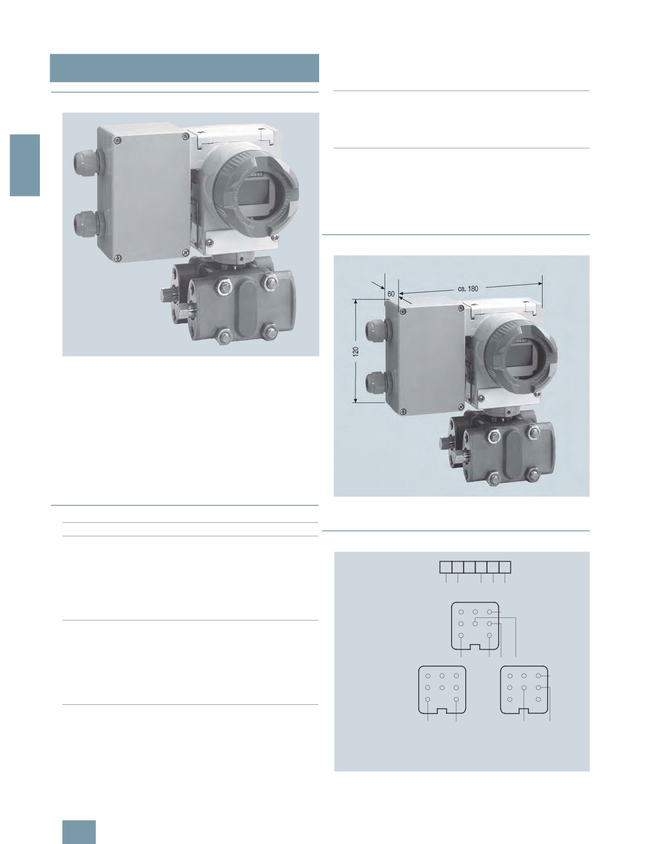
SITRANS P pressure transmitter with supplementary electronics for 4-
wire connection
Direct connection of the supplementary electronics to a
SITRANS P pressure transmitter from the DS III HART series pro-
duces a transmitter for four-wire connection.
The supplementary electronics cannot be attached to explosion-
protected pressure transmitters. The supplementary electronics
is fitted in a light metal housing which is mounted on the left side
of the pressure transmitter.
Note on ordering:
The supplementary electronics has to be be ordered through the
supplementary options of the pressure transmitter in question.
SITRANS P pressure transmitters with supplementary electronics for four-
■ Technical specifications
wire connection, dimension drawing, dimensions in mm (inch)
SITRANS P, supplementary electronics for 4-wire connection
■Schematics
Output
Output signal
0 ... 20 mA or 4 ... 20 mA
Load
Max. 750 Ω
&
)
/
1
- .
Voltage measurement
Linear (square-rooting in transmit-
ter if necessary)
6
Electrical isolation
Between power supply and input/
output
1
2
6*7 4 829
/
Measuring accuracy
To EN 60770-1
)
&
Conformity error (in addition to
≤ 0.15% of set span
transmitter)
6
Influence of ambient temperature
≤ 0.1% per 10 K
Power supply effect
≤ 0.1% per 10% change in volt-
1
2
1
2
age or frequency
/
/
Load effect
≤ 0.1% per 100% change
)
&
)
&
Rated conditions
Ambient temperature
-20 ... +80 °C (-4 ... +176 °F)
6
* & G
6
29
6
29
Storage temperature
-50 ... +85 °C (-58 ... +185 °F)
)G
6
29
6
4
Degree of protection
IP54 to EN 60529
'
(
6
Electromagnetic compatibility
EN 50081, EN 50082
(EMC)
Supplementary electronics for 4-wire connection, connection diagram
2/134

SITRANS P measuring instruments for pressure
SITRANS P Accessories
Supplementary electronics for 4-wire connection
Selection and Ordering data
Order code
Supplementary electronics for 4-wire
V77
connection
Order No. of the transmitter
7MF4.33-
-1AB. add "-Z" and Order code.
Power supply Electrical connection
2
24 V AC/DC
Terminals; 2 Pg screwed
1
glands, to left
2 Han 7D/Han 8U plugs
3
incl. mating connector, to left
1 Han 7D plug incl. mating
5
connector, angled
Terminals; 1 Pg screwed
6
gland, downwards
1 Han 8U plug incl. mating
9
connector, downwards
(observe arrangement of
plug and differential pressure
line)
230 V AC
Terminals; 2 Pg screwed
7
glands, to left
2 Han 7D plugs incl. mating
8
connector, to left
Output current
0 ... 20 mA
0
4 ... 20 mA
1
Selection and Ordering data
Order No.
Accessories
Instruction Manual
E86060-K6017-
German/English
A131-A3
2/135

SITRANS P measuring instruments for pressure
SITRANS P Accessories
Accessories / spare parts for SITRANS P
P300 and DS III series
Selection and Ordering data
Order No.
Selection and Ordering data
Order No.
Replacement measuring cell for pressure
7MF4990 -
Replacement measuring cell for absolute
F)
7MF4992 -
for SITRANS P, DS III, DS III PA and DS III FF series
pressure (from the pressure series)
77770 - 0DC0
77770 - 0DC0
for SITRANS P, DS III, DS III PA and DS III FF series
Measuring cell filling Measuring cell cleaning
Measuring cell filling Measuring cell cleaning
Silicone oil
Standard
1
Silicone oil
Standard
1
2
Inert liquid
Grease-free
3
Inert liquid
Grease-free
3
Measured span
Measured span
0.01 ... 1 bar g
(0.15 ... 14.5 psi g)
B
8.3 ... 250 mbar a
(0.12 ... 3.63 psi a)
D
0.04 ... 4 bar g
(0.58 ... 58 psi g)
C
43 ... 1300 mbar a
(0.62 ... 18.9 psi a)
F
0.16 ... 16 bar g
(2.32 ... 232 psi g)
D
0.16 ... 5 bar a
(2.32 ... 72.5 psi a)
G
0.63 ... 63 bar g
(9.14 ... 914 psi g)
E
1 ... 30 bar a
(14.5 ... 435 psi a)
H
1.6 ... 160 bar g
(23.2 ... 2320 psi g)
F
Wetted parts materials
4.0 ... 400 bar g
(58.0 ... 5802 psi g)
G
Seal diaphragm
Process connection
Wetted parts materials
Stainless steel
Stainless steel
A
Seal diaphragm
Process connection
Hastelloy
Stainless steel
B
Stainless steel
Stainless steel
A
Hastelloy
Hastelloy
C
Hastelloy
Stainless steel
B
Process connection
Hastelloy
Hastelloy
C
• Connection shank G½B to EN 837-1
0
Process connection
• Female thread ½-14 NPT
1
• Connection shank G½B to EN 837-1
0
• Oval flange made of stainless steel,
• Female thread ½-14 NPT
1
max. span 160 bar (2320 psi)
• Oval flange made of stainless steel,
- Mounting thread 7/16-20 UNF to EN 61518
2
max. span 160 bar (2320 psi)
- Mounting thread M10 to DIN 19213
3
- Mounting thread 7/16-20 UNF to EN 61518
2
Further designs
Order code
- Mounting thread M10 to DIN 19213
3
Please add "-Z" to Order No. and specify
Further designs
Order code
Order code.
Please add "-Z" to Order No. and specify
Acceptance test certificate
C12
Order code.
to EN 10204-3.1
Acceptance test certificate
C12
to EN 10204-3.1
F) Subject to export regulations AL: 9I999, ECCN: N.
2/136

SITRANS P measuring instruments for pressure
SITRANS P Accessories
Accessories / spare parts for SITRANS P
P300 and DS III series
Selection and Ordering data
Order No.
Selection and Ordering data
Order No.
Spare parts / Accessories
Spare parts / Accessories
Replacement measuring cell for absolute pres-
F)
7MF4993 -
Replacement measuring cell for differential
7MF499
4 -
sure (from the differential pressure series) for
pressure and PN 32/160 (MWP 464/2320 psi) for
77777- 0DC0
77777-
0DC0
SITRANS P, DS III, DS III PA and DS III FF series
SITRANS P, DS III, DS III PA and DS III FF series
Measuring cell filling Measuring cell cleaning
Measuring cell filling Measuring cell cleaning
2
Silicone oil
Standard
1
Silicone oil
Standard
1
Inert liquid
Grease-free
3
Inert liquid
Grease-free
3
Measured span
Measured span
8.3 ... 250 mbar a
(0.12 ... 3.63 psi a)
E) D
PN 32 (MWP 464 psi)
43 ... 1300 mbar a
(0.62 ... 18.9 psi a)
E) F
1 ... 20 mbar1)
(0.4015 ... 8.03 inH2O)
B
0.16 ... 5 bar a
(2.32 ... 72.5 psi a)
E) G
PN 160 (MWP 2320 psi)
1 ... 30 bar a
(14.5 ... 435 psi a)
H
1 ... 60 mbar
(0.4015 ... 24.09 inH2O)
C
5.3 ... 100 bar a
(76.9 ... 1450 psi a)
KE
2.5 ... 250 mbar
(1.004 ... 100.4 inH2O)
D
Wetted parts materials
6 ... 600 mbar
(2.409 ... 240.9 inH2O)
E
Seal diaphragm
Parts of measuring cell
16 ... 1600 mbar
(6.424 ... 642.4 inH2O)
F
50 ... 5000 mbar
(20.08 ... 2008 inH2O)
G
Stainless steel
Stainless steel
A
0.3 ... 30 bar
(4.35 ... 435 psi)
H
Hastelloy
Stainless steel
B
Hastelloy
Hastelloy
C
Wetted parts materials
Tantalum
Tantalum
E
(stainless steel process flanges)
Monel
Monel
E)
H
Seal diaphragm
Parts of measuring cell
Gold
Gold
L
Stainless steel
Stainless steel
A
Process connection
Hastelloy
Stainless steel
B
Female thread ¼-18 NPT with flange connection
Hastelloy
Hastelloy
C
• Sealing screw opposite process connection
Tantalum2)
Tantalum
E
- Mounting thread M10 to DIN 19213
0
Monel2)
Monel
H
- Mounting thread 7/16-20 UNF to EN 61518
2
Gold2)
Gold
L
• Vent on side of process flange1)
Process connection
- Mounting thread M10 to DIN 19213
4
Female thread ¼-18 NPT with flange connection
- Mounting thread 7/16-20 UNF to EN 61518
6
• Sealing screw opposite process connection
Non-wetted parts materials
- Mounting thread M10 to DIN 19213
0
• Stainless steel process flange screws
2
- Mounting thread 7/16-20 UNF to EN 61518
2
Further designs
Order code
• Vent on side of process flange
Please add "-Z" to Order No. and specify
- Mounting thread M10 to DIN 19213
4
Order code.
- Mounting thread 7/16-20 UNF to EN 61518
6
O-rings for process flanges
Non-wetted parts materials
(instead of FPM (Viton))
Stainless steel process flange screws
2
• PTFE (Teflon)
A20
Further designs
Order code
• FEP (with silicone core, approved for food)
A21
Please add "-Z" to Order No. and specify Order code.
• FFPM (Kalrez, compound 4079)
A22
• NBR (Buna N)
A23
O-rings for process flanges
(instead of FPM (Viton))
Acceptance test certificate
C12
• PTFE (Teflon)
A20
to EN 10204-3.1
• FEP (with silicone core, approved for food)
A21
Process connection G½A
D16
• FFPM (Kalrez, compound 4079)
A22
Remote seal flanges
D20
• NBR (Buna N)
A23
(not together with K01, K02 and K04)
Acceptance test certificate
C12
Vent on side for gas measurements
H02
to EN 10204-3.1
Process flanges
Remote seal flanges
D20
• without
K00
(not together with K01, K02 and K04)
• with process flange made of
Vent on side for gas measurements
H02
- Hastelloy
K01
Stainless steel process flanges for vertical
H03
- Monel
K02
differential pressure lines
- Stainless steel with PVDF insert
K04
(not together with K01, K02 and K04)
max. PN 10 (MWP 145 psi)
max. temperature of medium 90 °C (194 °F)
Process flanges
• without
K00
1) Not for span "5.3 ... 100 bar (76.9 ... 1450 psi)"
• with process flange made of
E) Combinations of the versions marked with E) are subject to the export
- Hastelloy
K01
regulations AL: 2B230, ECCN: N.
- Monel
K02
F) Subject to export regulations AL: 9I999, ECCN: N.
- Stainless steel with PVDF insert
K04
max. PN 10 (MWP 145 psi)
max. temperature of medium 90 °C (194 °F)
1) Not suitable for connection of remote seal
2) Only together with max. spans 250, 1600, 5000 and 30000 mbar
(3.63, 23.2, 72.5 and 435 psi).
2/137

SITRANS P measuring instruments for pressure
SITRANS P Accessories
Accessories / spare parts for SITRANS P
P300 and DS III series
Selection and Ordering data
Order No.
Selection and Ordering data
Order No.
Spare parts / Accessories
Spare parts / Accessories
Replacement measuring cell for differential
7MF4995 -
Replacement measuring cell for level
7MF4996 -
pressure and PN 420 (MWP 6092 psi) for
for SITRANS P, DS III, DS III PA and
77777- 0DC0
77777- 0DC0
SITRANS P, DS III, DS III PA and
DS III FF series
DS III FF series
2
Measuring cell filling Measuring cell cleaning
Measuring cell filling Measuring cell cleaning
Silicone oil
Standard
1
Silicone oil
Standard
1
Rated measuring range
Measured span
250 mbar
(3.63 psi)
D
2.5 ... 250 mbar
(1.004 ... 100.4 inH2O)
D
600 mbar
(8.70 psi)
E
6 ... 600 mbar
(2.409 ... 240.9 inH2O)
E
1600 mbar
(23.2 psi)
F
16 ... 1600 mbar
(6.424 ... 642.4 inH2O)
F
5 bar
(72.5 psi)
G
50 ... 5000 mbar
(20.08 ... 2008 inH2O)
G
Wetted parts materials
0.3 ... 30 bar
(4.35 ... 435 psi)
H
(stainless steel process flanges)
Wetted parts materials
Seal diaphragm
Parts of measuring cell
(stainless steel process flanges)
Stainless steel
Stainless steel
A
Seal diaphragm
Parts of measuring cell
Process connection of low-pressure side
Stainless steel
Stainless steel
A
Female thread ¼-18 NPT with flange
Hastelloy
Stainless steel
B
connection
Gold1)
Gold
L
• Sealing screw opposite process connection
Process connection
- Mounting thread M10 to DIN 19213
0
Female thread ¼-18 NPT with flange
- Mounting thread 7/16-20 UNF to EN 61518
2
connection
• Sealing screw opposite process connection
Non-wetted parts materials
• Stainless steel process flange screws
2
- Mounting thread M12 to DIN 19213
1
3
Further designs
Order code
- Mounting thread 7/16-20 UNF to EN 61518
• Vent on side of process flange
Please add "-Z" to Order No. and specify Order
code.
- Mounting thread M12 to DIN 19213
5
- Mounting thread 7/16-20 UNF to EN 61518
7
O-rings for process flanges
(instead of FPM (Viton))
Non-wetted parts materials
• PTFE (Teflon)
A20
• Stainless steel process flange screws
2
• FEP (with silicone core, approved for food)
A21
Further designs
Order code
• FFPM (Kalrez, compound 4079)
A22
• NBR (Buna N)
A23
Please add "-Z" to Order No. and specify Order
code.
Acceptance test certificate
C12
O-rings for process flanges
to EN 10204-3.1
(instead of FPM (Viton))
without process flanges
K00
• PTFE (Teflon)
A20
• FEP (with silicone core, approved for food)
A21
• FFPM (Kalrez, compound 4079)
A22
• NBR (Buna N)
A23
Acceptance test certificate
C12
to EN 10204-3.1
Stainless steel process flanges for vertical dif-
H03
ferential pressure lines
without process flanges
K00
1) Not together with max. span 600 mbar (240.9 inH2O)
2/138

SITRANS P measuring instruments for pressure
SITRANS P Accessories
Accessories / spare parts for SITRANS P
P300 and DS III series
Selection and Ordering data
Order No.
Selection and Ordering data
Order No.
Spare parts / Accessories
Sealing screws
(1 set = 2 off) for process flange
Mounting bracket and mounting parts
• made of stainless steel
7MF4997-1CG
for pressure transmitters
DS III, DS III PA and DS III FF series
• made of Hastelloy
F)
7MF4997-1CH
(7MF403.-
-..C.)
Screw plug with valve (1 set = 2 off)
for absolute pressure transmitters
2
• made of stainless steel
}
7MF4997-1CP
DS III, DS III PA and DS III FF series
(7MF423.-
-..C.)
• made of Hastelloy
F)
7MF4997-1CQ
• made of steel
7MF4997-1AB
Electronics
• made of stainless steel
7MF4997-1AH
• for DS III series
7MF4997-1DK
Mounting bracket and mounting parts
• for DS III PA series
7MF4997-1DL
for pressure transmitters
• for DS III FF series
7MF4997-1DM
DS III, DS III PA and DS III FF series
Connection board
(7MF403.-
-..A., -..B. and -..D.)
• for DS III series
7MF4997-1DN
for absolute pressure transmitters
DS III, DS III PA and DS III FF series
• for DS III PA and DS III FF series
7MF4997-1DP
(7MF423.-
-..A., -..B. and -..D.)
O-rings for process flanges made of
• Made of steel
7MF4997-1AC
• FPM (Viton)
F)
7MF4997-2DA
• Made of stainless steel
}
7MF4997-1AJ
• PTFE (Teflon)
F)
7MF4997-2DB
Mounting bracket and mounting parts
• FEP (with silicone core, approved for food)
F)
7MF4997-2DC
for differential pressure transmitters with flange
• FFPM (Kalrez, compound 4079)
F)
7MF4997-2DD
thread M10
• NBR (Buna N)
F)
7MF4997-2DE
DS III, DS III PA and DS III FF series
(7MF433.-... and 7MF443.-...)
Weldable sockets for PMC connection
for DS III and P300 series
• made of steel
7MF4997-1AD
• PMC Style Standard: Thread 1½“
7MF4997-2HA
• made of stainless steel
}
7MF4997-1AK
• PMC Style Mini bolt: front-flush 1“
F)
7MF4997-2HB
Mounting bracket and mounting parts
Sealing rings for PMC connection
for differential pressure transmitters with flange
(packing unit: 5 pcs)
thread M12
DS III, DS III PA and DS III FF series
• Sealing ring made of PTFE for PMC Style
F)
7MF4997-2HC
(7MF453.-...)
Standard: Thread 1½"
• made of steel
7MF4997-1AE
• Sealing ring made of Viton for PMC Style
F)
7MF4997-2HD
Minibolt: front-flush 1“
• made of stainless steel
7MF4997-1AL
Weldable socket for TG 52/50- and
Mounting bracket and mounting parts
TG 52/150 connection
for differential and absolute pressure trans-
for DS III and P300 series
mitters with flange thread 7/16-20 UNF
• TG 52/50 connection
7MF4997-2HE
DS III, DS III PA and DS III FF series
(7MF433.-..., 7MF443.-... and 7MF453.-...)
• TG 52/150 connection
7MF4997-2HF
• made of steel
7MF4997-1AF
Seals for TG 52/50 and TG 52/150 made of
7MF4997-2HG
• made of stainless steel
7MF4997-1AM
silicone
Cover
Seals for flange connection with flush-
Made of die-cast aluminium, including gasket,
mounted diaphragm
for DS III, DS III PA and DS III FF series
Material FPM (Viton), 10 units
• without window
F)
7MF4997-1BB
• DN 25, PN 40 (M11)
F)
7MF4997-2HH
• with window
}
7MF4997-1BE
• DN 25, PN 100 (M21)
F)
7MF4997-2HJ
F)
• 1", class 150 (M40)
F)
7MF4997-2HK
• 1", class 300 (M45)
F)
7MF4997-2HL
Cover
Made of stainless steel, including gasket,
Mounting bracket and mounting parts
for DS III, DS III PA and DS III FF series
for P300
• without window
F)
7MF4997-1BC
• Made of stainless steel
7MF8997-1AA
• with window
F)
7MF4997-1BF
Lid without window for P300
Digital indicator
• Gasket not included
7MF8997-1BA
Including mounting material
7MF4997-1BR
Lid with glass window for P300
for DS III, DS III PA and DS III FF series
• Gasket not included
7MF8997-1BD
Measuring-point label
7MF8997-1BG
NBR housing gasket for P300
• without inscription (5 off)
7MF4997-1CA
• with inscription (1 off)
7MF4997-1CB-Z
Measuring point label for P300
Data according to Y01 or Y02, Y15 and Y16
Y..:
• Unlabeled
7MF8997-1CA
(see "SITRANS P pressure transmitters")
Cable gland for P300
Mounting screws
7MF4997-1CD
• Metal
7MF8997-1EA
for measuring-point label, earthing and con-
• Plastic (blue)
7MF8997-1EB
nection terminals or for digital indicator (50 off)
} Available ex stock
F) Subject to export regulations AL: 9I999, ECCN: N.
2/139
SITRANS P measuring instruments for pressure
SITRANS P Accessories
Accessories / spare parts for SITRANS P
P300 and DS III series
Selection and Ordering data
Order No.
Instruction Manual1)
• for P300 series with HART communication
- German
A5E00359580
- English
A5E00359579
- French
A5E00359578
2
- Spanish
A5E00359576
- Italian
A5E00359577
- Leporello German/English
A5E00359581
• for P300 series with PROFIBUS PA communi-
cation
- German
A5E00414587
- English
A5E00414588
- French
A5E00414589
- Spanish
A5E00414590
- Italian
A5E00414591
- Leporello German/English
A5E00414592
• for DS III series
- German
A5E00047090
- English
A5E00047092
- French
A5E00053218
- Spanish
A5E00053219
- Italian
A5E00053220
• for DS III PA series
- German
A5E00053275
- English
A5E00053276
- French
A5E00053277
- Spanish
A5E00053278
- Italian
A5E00053279
• for DS III FF series
- German
A5E00279627
- English
A5E00279629
- French (planned)
A5E00279630
- Spanish (planned)
A5E00279632
- Italian (planned)
A5E00279631
Brief instructions (Leporello)
• for DS III series, German, English
A5E00047093
• for DS III PA series, German, English
A5E00053274
• for DS III FF series, German, English
A5E00282355
CD with documentation
G) A5E00090345
for P300, DS III, DS III PA and DS III FF series
German, English, French, Italian, Spanish
Instruction Manual
for replacement of electronics, measuring cell
and connection board
• German/English
A5E00078060
HART modem
• with RS232 interface
}
7MF4997-1DA
D)
• with USB interface
}
7MF4997-1DB
D)
Supplementary electronics for 4-wire connec-
see page 2/134
tion
} Available ex stock
Power supply units see "SITRANS I power supply units and input isola-
tors".
1) You can download the Instruction Manuals free-of-charge from the Internet
site www.siemens.com/sitransp.
D) Subject to export regulations AL: N, ECCN: EAR99H.
G) Subject to export regulations AL: N, ECCN: 5D992B1.
2/140

SITRANS P measuring instruments for pressure
SITRANS P Accessories
Accessories / spare parts for SITRANS P
P300 and DS III series
■Dimensional drawings
2
Mounting bracket for SITRANS P gage and absolute pressure transmitter, DS III series
Material of mounting bracket: Sheet-steel Mat. No. 1.0330, chrome-plated, or stainless steel Mat. No. 1.4301 (304)
Mounting bracket for SITRANS P differential pressure transmitter, DS III series,
Material of mounting bracket: Sheet-steel Mat. No. 1.0330, chrome-plated, or stainless steel Mat. No. 1.4301 (304)
2/141

SITRANS P measuring instruments for pressure
SITRANS P Accessories
Factory-mounting of valve manifolds on
SITRANS P transmitters
The 7MF9011-4FA valve manifolds are sealed with PTFE sealing
■Overview
tape between the transmitter and the valve manifold.
SITRANS P transmitters
The 7MF9411-5BA and 7MF9411-5CA valve manifolds are
• P300 for relative and absolute pressure,
sealed with PTFE sealing rings between the transmitter and the
valve manifold.
• DS III for relative and absolute pressure (both designs) and
• DS III for differential pressure
Once installed, the complete unit is checked under pressure for
2
leaks and is certified leak-proof with a factory certificate to
can be delivered factory-fitted with the following valve manifolds:
EN 10204 - 2.2.
• 7MF9011-4EA and 7MF9011-4FA valve manifolds for relative
All valve manifolds should preferably be secured with the re-
pressure and absolute pressure transmitters
spective mounting brackets. The transmitters are mounted on
• 7MF9411-5BA and 7MF9411-5CA valve manifolds for abso-
the valve manifold and not on the unit itself.
lute pressure and differential pressure transmitters
If you order a mounting bracket when choosing the option "Fac-
tory mounting of valve manifolds", you will receive a mounting
■Design
bracket for the valve manifold instead of a bracket for mounting
the transmitter.
The 7MF9011-4EA valve manifolds are sealed with gaskets
made of PTFE between transmitter and the valve manifold as
If you order an acceptance test certificate 3.1 to EN10204 when
standard. Soft iron, stainless steel and copper gaskets are also
choosing the option "Factory mounting of valve manifolds", a
available for sealing purposes if preferred.
separate certificate is provided for the transmitters and the valve
manifolds respectively.
■Selection and Ordering data
7MF9011-4FA valve block on
7MF9411-5BA valve manifold on
relative and absolute pressure transmitters
absolute and differential pressure transmitters
Add -Z to the Order No. of the transmitter
Order
Add -Z to the Order No. of the transmitter
Order
and add order codes.
code
and add order codes.
code
SITRANS P DSIII
T03
SITRANS P DSIII
7MF403.-...1.-..., 7MF423.-...1.-... and
7MF433.-…, 7MF443.-… and
1)
7MF453.-…
SITRANS P300
7MF802.-...1.-...
mounted with gaskets made of PTFE and
With process connection female thread
screws made of
½-14 NPT in-sealed with PTFE sealing
• chromized steel
U01
strip
• stainless steel
U02
Delivery incl. high-pressure test certified
by factory certificate to EN10204-2.2
Delivery incl. high-pressure test certified
by factory certificate to EN10204-2.2
7MF9011-4EA valve block on
relative and absolute pressure transmitters
7MF9411-5CA valve manifold on differential pressure transmitters
Add -Z to the Order No. of the transmitter
Order
Add -Z to the Order No. of the transmitter Order
and add order codes.
code
and add order codes.
code
SITRANS P DSIII
T02
SITRANS P DSIII
7MF403.-...0.-..., 7MF423.-...0.-... and
7MF443.-... und 7MF453.-…1)
SITRANS P300
mounted with gaskets made of PTFE and
7MF802.-...0.-...
screws made of
with process connection collar G1/2 A to
• chromized steel
U03
EN837-1 with gasket made of PTFE
between valve manifold and transmitter
• stainless steel
U04
Alternative sealing material:
Delivery incl. high-pressure test certified
by factory certificate to EN10204-2.2
• soft iron
A70
Further designs:
• stainless steel, Mat. No. 14571
A71
Delivery includes mounting bracket and
• copper
A72
mounting clips made of
Delivery incl. high-pressure test certified
• steel
A01
by factory certificate to EN10204-2.2
• stainless steel
A02
Further designs:
(instead of the mounting bracket sup-
Delivery includes mounting brackets and
A02
plied with the transmitter)
mounting clips made of stainless steel
(instead of the mounting bracket sup-
Supplied acceptance test certificate to
C12
plied with the transmitter)
EN10204-3.1 for transmitters and
mounted valve manifold
Supplied acceptance test certificate to
C12
EN 10204- 3.1 for transmitters and
Oil and grease-free cleaning for oxygen
E10
mounted valve manifold
operation
Oil and grease-free cleaning for oxygen
E10
1) For 7MF453.-... transmitters, you require a 7/10-20 UNF connection thread
operation
in the process flange.
2/142

SITRANS P measuring instruments for pressure
SITRANS P Accessories
Factory-mounting of valve manifolds on
SITRANS P transmitters
■Dimensional drawings
Valve manifolds mounted on SITRANS P DS III
2
Valve manifold 7MF9011-4EA with mounted relative pressure and abso-
Valve manifold 7MF9011-4EA with mounted relative pressure and abso-
lute pressure transmitters
lute pressure transmitters, dimensions in mm (inch)
Valve manifold 7MF9011-4FA with mounted relative pressure and abso-
Valve manifold 7MF9011-4FA with mounted relative pressure and abso-
lute pressure transmitters
lute pressure transmitters, dimensions in mm (inch)
2/143

SITRANS P measuring instruments for pressure
SITRANS P Accessories
Factory-mounting of valve manifolds on
SITRANS P transmitters
2
Valve manifold 7MF9411-5BA with mounted differential pressure trans-
Valve manifold 7MF9411-5CA with mounted differential pressure trans-
mitter
mitter
5
Valve manifold 7MF9411-5BA with mounted differential pressure transmitter, dimensions in mm (inch)
5
Valve manifold 7MF9411-5CA with mounted differential pressure transmitter, dimensions in mm (inch)
2/144

SITRANS P measuring instruments for pressure
SITRANS P Accessories
Factory-mounting of valve manifolds on
SITRANS P transmitters
Valve manifolds mounted on SITRANS P300
2
Valve manifold 7MF9011-4EA with mounted relative pressure and abso-
Valve manifold 7MF9011-4EA with mounted relative pressure and abso-
lute pressure transmitters, dimensions in mm (inch)
lute pressure transmitters
Valve manifold 7MF9011-4FA with mounted relative pressure and abso-
Valve manifold 7MF9011-4FA with mounted relative pressure and abso-
lute pressure transmitters
lute pressure transmitters, dimensions in mm
2/145

SITRANS P measuring instruments for pressure
Transmitters for hydrostatic level
MPS series (submersible sensor)
■Overview
9
(
:;
!+
"
!+ "
2
G
SITRANS P pressure transmitters, MPS series, mode of operation and
wiring diagram
On one side of the sensor, the diaphragm is exposed to the hy-
drostatic pressure which is proportional to the submersion
SITRANS P pressure transmitters, MPS series (submersible sensor)
depth. This pressure is compared with atmospheric pressure.
SITRANS P pressure transmitters, MPS series, are submersible
Pressure compensation is carried out using the vent pipe in the
sensors for hydrostatic level measurements.
connection cable.
The pressure transmitters of the MPS series are available for var-
The hydrostatic pressure of the liquid column acts on the sensor
ious measuring ranges and with explosion protection as an op-
diaphragm, and transmits the pressure to the piezo-resistive
tion.
bridge in the sensor.
A junction box and a cable hanger are available as accessories
The output voltage of the sensor is applied to the electronic cir-
for simple installation.
cuit where it is converted into an output current of 4 to 20 mA.
The cable of the 7MF1570 transmitter must always be connected
■ Benefits
in the supplied junction box. The junction box has to be installed
near the measuring point.
• Compact design
• Simple installation
If the medium is anything other than water, it is also necessary to
check compatibility with the specified materials of the transmit-
• Small error in measurement (0.3%)
ter.
• Degree of protection IP68
■Integration
■Application
SITRANS P pressure transmitters, MPS series, are used in the
following branches for example:
• Oil and gas industries
• Shipbuilding
• Water supply
■Design
SITRANS P pressure transmitters, MPS series, have a flush-
mounted piezo-resistive sensor with stainless steel diaphragm.
These pressure transmitters are equipped with an electronic cir-
cuit fitted together with the sensor in a stainless steel housing.
The cable also contains a strength cord and vent pipe.
The diaphragm is protected against external influences by a
protective cap.
Junction box 7MF1570-8AA, opened
The sensor, electronic circuit and cable are sealed in a common
housing of small dimensions.
The pressure transmitter is temperature-compensated for a wide
temperature range.
■Function
SITRANS P pressure transmitters, MPS series, are for measuring
the liquid levels in wells, tanks, channels and dams.
2/146

SITRANS P measuring instruments for pressure
Transmitters for hydrostatic level
MPS series (submersible sensor)
Long-term stability
Zero and span
• 1 ... 6 mH2O (3 ... 18 ftH2O)
0.25% of full-scale value/year
• ≥ 6 mH2O (≥ 18 ftH2O)
0.2% of full-scale value/year
Rated operating conditions
2
Ambient conditions
• Process temperature
-10 ... +80 °C (+14 ... +176 °F)
• Storage temperature
-40 ... +100 °C (-40 ... +212 °F)
Degree of protection to
IP68
DIN EN 60529
Design
Weight
• Pressure transmitters
≈ 0.4 kg (≈ 0.88 lb)
• Cable
0.08 kg/m (≈ 0.054 lb/ft)
Electrical connection
Cable with 2 conductors with
screen and vent pipe, strength
cord (max. 300 N (67.44 lbf)
Material
• Seal diaphragm
Stainless steel, mat. No.
1.4571/316 Ti
• Casing
Stainless steel, mat. No.
1.4571/316 Ti
• Gasket
Viton
• Connecting cable
Optionally
PE/HFFR sheath (non-halogen)
or
FEP sheath
Power supply
Measuring point setup, in principle
Terminal voltage on pressure trans-
10 ... 36 V DC
mitter (UB)
■ Technical specifications
Certificate and approvals
SITRANS P pressure transmitters, MPS series (submersible sensor)
The transmitter is not subject to the pressure equipment directive
(DGRL 97/23/EC)
Mode of operation
Explosion protection
Measuring principle
Piezo-resistive
• Intrinsic safety "i"
TÜV 03 ATEX 2004X
Input
- Identification
Ex II 1 G EEx ia IIC T4
Measured variable
Hydrostatic level
Measuring range
Maximum working pressure
Junction box
• 0 ... 2 mH2O (0 ... 6 ftH2O)
• 1.4 bar (20.3 psi) (corresponds
to 14 mH2O (42 ftH2O))
Application
For connecting the transmitter
cable
• 0 ... 4 mH2O (0 ... 12 ftH2O)
• 1.4 bar (20.3 psi) (corresponds
to 14 mH2O (42 ftH2O))
Design
• 0 ... 5 mH2O (0 ... 15 ftH2O)
• 1.4 bar (20.3 psi) (corresponds
Weight
0.2 kg (0.44 lb)
to 14 mH2O (42 ftH2O))
Electrical connection
2 x 3-way (28 ... 18 AWG)
• 0 ... 6 mH2O (0 ... 18 ftH2O)
• 3.0 bar (43.5 psi) (corresponds
to 30 mH2O (90 ftH2O))
Cable entry
2 x M20x1.5
• 0 ... 10 mH2O (0 ... 30 ftH2O)
• 3.0 bar (43.5 psi) (corresponds
Enclosure material
Polycarbonate
to 30 mH2O (90 ftH2O))
Vent pipe for atmospheric pressure
• 0 ... 20 mH2O (0 ... 60 ftH2O)
• 6.0 bar (87.0 psi) (corresponds
Screw for cable strength cord
to 60 mH2O (180 ftH2O))
Rated operating conditions
Output
Degree of protection to DIN EN
IP54
Output signal
4 ... 20 mA
60529
Accuracy
To EN 60770-1
Error in measurement (including
0.3% of full-scale value (typical)
non-linearity, hysteresis and repeat-
Cable hanger
ability, at 25 °C (77 °F))
Application
For mounting the transmitter
Influence of ambient temperature
Design
Zero and span
Weight
0.16 kg (0.35 lb)
• 1 ... 6 mH2O (3 ... 18 ftH2O)
0.45%/10 K of full-scale value
Material
Galvanized steel, polyamide
• ≥ 6 mH2O (≥ 18 ftH2O)
0.3%/10 K of full-scale value
2/147
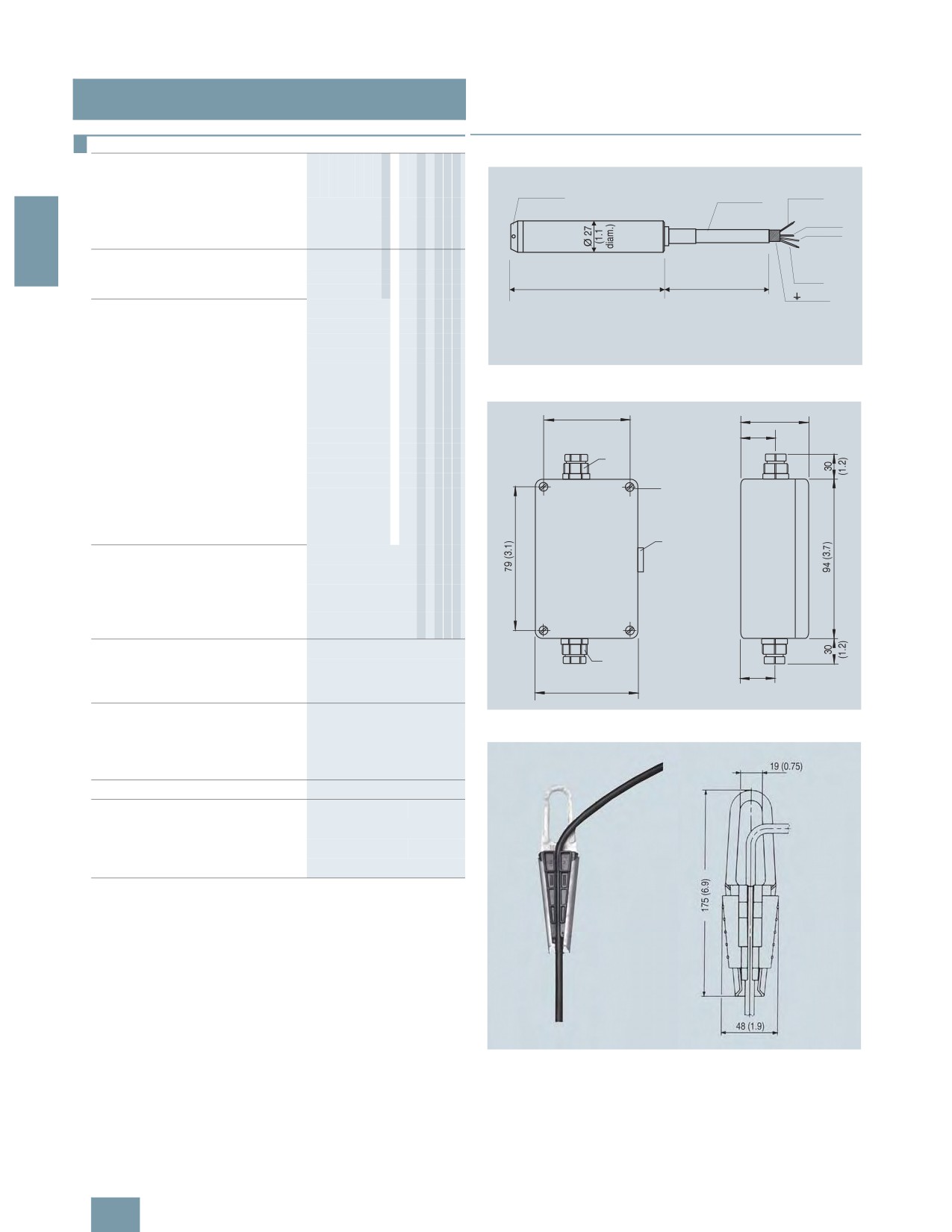
SITRANS P measuring instruments for pressure
Transmitters for hydrostatic level
MPS series (submersible sensor)
Selection and Ordering data
Order No.
■Dimensional drawings
SITRANS P pressure transmitters
C)
7MF15
7
0
-77A07
7
7
7
for pressure, MPS series (submers-
ible sensor)
'
+
(
(
!+
"
2-wire system
G
2
Note: Junction box and cable hanger
included in delivery
(
!
( "
Cable material
PE
}
1
!+ "
/4 !1
"
FEP
5
Measuring range Cable length L
0 ... 2 mH2O
10 m
}
C
+
(
( 4 & ! &&"
. !+
,
+
:86'' "
'
=+
+
(
/ .. !
24
("
0 ... 4 mH2O
10 m
}
D
G
!
)"
. !
. "
0 ... 5 mH2O
25 m
}
B
'
()=&
. !) =
."(
!+
,
*"
0 ... 6 mH2O
25 m
}
E
0 ... 10 mH2O
25 m
}
F
SITRANS P pressure transmitters, MPS series, dimensions in mm (inch)
0 ... 20 mH2O
25 m
}
G
0 ... 6 ftH2O
32 ft
K
50 (1.97)
57 (2.25)
0 ... 12 ftH2O
32 ft
L
22
0 ... 18 ftH2O
82 ft
M
(0.87)
M20x1.5
0 ... 30 ftH2O
82 ft
N
0 ... 60 ftH2O
82 ft
P
Mounting
Special measuring range/Special cable
Z
J
1
Y
hole
length 1)
Specify measuring range and cable
length in plain text
Venting
Explosion protection
valve
1
• without
}
• with, type of protection "Intrinsic safe-}
2
ty" (Ex II 1 G EEx ia IIC T4)
• With approval for drinking water to
}
6
WRAS and ACS
D)
Further designs
Order code
M20x1.5
Quality inspection certificate (Factory
C11
22
calibration) to IEC 60770-2, add "-Z" to
65 (2.56)
(0.87)
Order No. and Order code.
Order No.
Junction box, dimensions in mm (inch)
Quality inspection certificate (Factory
7MF1564-8CC11
calibration) to IEC 60770-2 supplied
later, specify factory no. of transmitter
for this porpose.
Accessories (as spare parts)
Junction box
7MF1570-8AA
for connecting the transmitter cable
Cable hanger
7MF1570-8AB
for mounting the pressure transmitter
} Available ex stock
Power supply units see "SITRANS I power supply units and input isola-
tors".
1) Special measuring ranges between 0 ... 1 mH2O (0 ... 3 ftH2O)
and 0 ... 200 mH2O (0 ... 656 ftH2O) and special cable lengths up to
1000 m (3281ft) are possible. With Ex versions the max.
special cable length is 50 m (150 ft). The length of free-hanging cable
should not exceed 375 m.
C) Subject to export regulations AL: N, ECCN: EAR99.
D) Subject to export regulations AL: N, ECCN: EAR99H.
Cable hanger, dimensions in mm (inch)
2/148

SITRANS P measuring instruments for pressure
Transmitters for hydrostatic level
MPS series (submersible sensor)
■More information
Determination of the measuring range in case of media with
a density ≠ 1000 kg/m3 (medium ≠ water)
2
+
ρ
Calculation of the measuring range:
p = ρ x g x H
with:
ρ = density of medium
g = local acceleration due to gravity
H = maximum level
Example:
Medium: Diesel fuel = 850 kg/m3
Acceleration due to gravity: 9.81 m/s2
Start-of-scale : 0 m
Maximum level: 6,2 m
Calculation:
p = 850 kg/m3 x 9.81 m/s2 x 6.2 m
p = 51698.7 N/m2
p = 517 mbar
Transmitter to be ordered:
7MF1570-5ZA02-Z
J1Y: 0 ... 517 mbar; able length e.g. 8 m
2/149

SITRANS P measuring instruments for pressure
Remote seals for transmitters and pressure gages
Technical description
capillaries of equal length must always be used to connect a re-
■Overview
mote seal to a pressure transmitter for differential pressure.
In many cases the pressure transmitter and the measured me-
The remote seal can be optionally equipped with a projecting di-
dium have to be physically separated. It is then necessary to use
aphragm (tube).
a remote seal.
Remote seals of sandwich design are fitted with a dummy
The remote seals can be used with the following SITRANS P
flange.
2
pressure transmitter series:
Designs
• Pressure (P300, DS III, DS III PA, DS III FF)
• Absolute pressure (P300, DS III, DS III PA, DS III FF)
Diaphragm seal
• Differential pressure and flow (DS III, DS III PA, DS III FF)
With diaphragm seals, the pressure is measured by means of a
flat diaphragm which rests in a bed.
Note
The following types of diaphragm seals exist:
When configuring your remote seal, be sure to read the informa-
tion about transmission response, temperature error and re-
sponse time to be found in the sections "Function" and "Technical
data". Only then will the remote seal work to optimum effect.
■ Benefits
• No direct contact between the pressure transmitter and the
medium
• Individual configuration of the pressure transmitter for perfect
adaptation to the operating conditions
• Available in many versions
• Specially designed for difficult operating conditions
• Quick-release versions available for the food industry
Diaphragm seal of sandwich design without (left) and with a projecting
diaphragm (tube)
■Application
• Sandwich design
• Sandwich design with projecting diaphragm (tube) to DIN or
Remote seal systems should be used if a separation between
ASME which are secured using a dummy flange.
the measured medium and the measuring instrument is essential
or appropriate.
Examples of such cases:
• The temperature of the medium is outside the limits specified
for the pressure transmitter.
• The medium is corrosive and requires diaphragm materials
which are not available for the pressure transmitter.
• The medium is highly viscous or contains solids which would
block the measuring chambers of the
pressure transmitter.
• The medium may freeze in the measuring chambers or pulse
line.
• The medium is heterogeneous or fibrous.
Diaphragm seal of flange design without (left) and with a projecting dia-
• The medium tends towards polymerization or crystallization.
phragm (tube)
• Flange design
• The process requires quick-release remote seals, as neces-
sary e.g. in the food industry for fast cleaning.
• Flange design with projecting diaphragm (tube) to DIN or
ASME, secured using holes in the flange.
• The process requires cleaning of the measuring point, e.g. in
a batch process.
■Design
A remote seal system consists of the following components.
• Pressure transmitter
• One or two remote seals
• Filling liquid
• Connection between pressure transmitter and remote seal (di-
rect mounting or by means of capillary)
The volume in contact with the measured medium is terminated
by a flat elastic diaphragm lying in a bed. Between the dia-
phragm and the pressure transmitter is the filling liquid.
Quick-release diaphragm seal
• Quick-release remote seals, e.g. to DIN 11851, SMS standard,
In many cases, a capillary has to be connected between the re-
IDF standard, APV RJT standard, clamp connection, etc.
mote seal and the pressure transmitter in order e.g. to minimize
temperature effects on the latter when hot media are involved.
• Miniature diaphragm seal with male thread for screwing into
tapped holes
However, the capillary influences the response time and the tem-
• Remote seals with customer-specific process connections
perature response of the complete remote seal system. Two
2/150

SITRANS P measuring instruments for pressure
Remote seals for transmitters and pressure gages
Technical description
■Function
The measured pressure is transferred from the diaphragm to the
filling liquid and passes through the capillary to the measuring
chamber of the pressure transmitter. The interior of the dia-
phragm seal and of the capillary, as well as the measuring cham-
ber of the transmitter, are filled gas-free by the filling liquid.
2
Transmission response
The transmission response of a remote seal is characterized by
the following variables:
• Temperature error
Miniature diaphragm seal with diaphragm flush with front
• Adjustment time
• Miniature diaphragm seals
Temperature error
The quick-release remote seals are used above all in the food in-
Temperature errors are caused by the change of volume of the
dustry. Their design means that the measured medium cannot
filling liquid due to temperature variations. To select the right re-
accumulate in dead volumes. The quick-release clamp present
mote seal you must calculate the temperature error.
on the remote seal means that quick dismounting is possible for
cleaning.
Below you will find an overview of the factors which influence the
size of the temperature error, as well as information on how to
Clamp-on seal
calculate the temperature error.
The temperature error is dependent on the following variables:
• Rigidity of the diaphragm used
• Filling liquid used
• Influence of the filling liquid underneath the process flanges or
in the connection shank of the pressure transmitter
• Internal diameter of the capillary: The bigger the internal diam-
eter, the bigger the temperature error
• Length of the capillary: The longer the capillary, the bigger the
temperature error
Diaphragm rigidity
Clamp-on seal with quick-release design (left) and for flange mounting
The rigidity of the diaphragm is of decisive importance. The big-
ger the diameter of the diaphragm, the softer the diaphragm and
With clamp-on seals, the pressure is first measured using a cy-
the more sensitively it reacts to temperature-induced changes in
lindrical diaphragm positioned in a pipe, and then transmitted to
volume of the filling liquid.
the pressure transmitter by means of the filling liquid.
The result is that small measuring ranges are only possible with
The clamp-on seal is a special design for flowing media. It con-
large diaphragm diameters.
sists of a cylindrical pipe in which a cylindrical diaphragm is em-
bedded. Since it is completely integrated in the process pipe, no
Other factors apart from diaphragm rigidity which also play a
turbulences, dead volumes or other obstructions to the flow oc-
role:
cur. Furthermore, the clamp-on seal can be cleaned by a pig.
• Diaphragm thickness
The following types of clamp-on seals exist:
• Diaphragm material
• Quick-release clamp-on seals, e.g. to DIN 11851, SMS stan-
• Coatings if present
dard, IDF standard, APV/RJT standard, clamp connection etc.
Filling liquid
The quick-release facility attached to the remote seal enables
the seal to be removed quickly for cleaning purposes.
Every filling liquid reacts to temperature variations with a change
• Clamp-on seals for flanging to EN or ASME.
of volume. Temperature errors can be minimized by selecting a
suitable filling liquid, but the filling liquid must also be appropri-
• Clamp-on seals with customer-specific process connections.
ate for the temperature limits and operating pressure. Further-
Note:
more, the filling liquid must also be physiologically harmless.
The pressure data on the transmitter and the remote seal must
Since the filling liquid is present under the diaphragm, in the
be observed with regard to pressure/temperature behavior.
capillary and under the process flange of the pressure transmit-
ter (or in the connection shank), the temperature error must be
calculated separately for each combination.
Note:
When operating in the low-pressure range, also during commis-
sioning, it is recommended to use a vacuum-proof remote seal
(see Selection and Ordering data).
An example of a temperature error calculation can be found in
the section "Technical Specifications".
2/151
SITRANS P measuring instruments for pressure
Remote seals for transmitters and pressure gages
Technical description
Response time
The response time is dependent on the following factors:
• Internal diameter of the capillary: The bigger the internal diam-
eter, the shorter the response time
• Viscosity of the filling liquid The greater the viscosity, the
longer the response time
2
• Length of the capillary: The longer the capillary, the longer the
response time
• Pressure in the pressure measuring system: The higher the
pressure, the shorter the response time
Recommendations
The following should be observed to obtain an optimum combi-
nation of transmitter and remote seal:
• Choose the biggest possible diameter for the remote seal. The
effective diameter of the seal diaphragm is then bigger and
the temperature error smaller.
• Choose the shortest possible capillary. The response time is
then shorter and the temperature error smaller
• Choose the filling liquid with the least viscosity and the small-
est coefficient of expansion. Make sure, however, that the fill-
ing liquid meets the process requirements with regard to pres-
sure, vacuum and temperature. And ensure that the filling
liquid and the medium are compatible with one another.
• Note the following points for use in the vacuum range:
- The pressure transmitter must always be positioned below
the lowest spigot.
- The operating range of some filling liquids is very limited with
regard to the permissible temperature of the medium.
- A vacuum-proof seal is necessary for continuous operation
in the low-pressure range.
• Recommendations for the minimum span can be found in the
section "Technical data".
Note
The remote seals listed here are a selection of the most common
designs. On account of the large variety of process connections,
certain remote seals which are not listed here may be available
nevertheless.
Other versions can be:
• Other process connections, standards
• Aseptic or sterile connections
• Other dimensions
• Other nominal pressures
• Special diaphragm materials, including coatings
• Other sealing faces
• Other filling liquids
• Other capillary lengths
• Sheathing of capillaries with protective hose
• Calibration at higher/lower temperatures etc.
Please contact your Siemens Regional Office for more infor-
mation.
2/152
SITRANS P measuring instruments for pressure
Remote seals for transmitters and pressure gages
Technical description
■ Technical specifications
Temperature error Diaphragm seals
Temperature errors of diaphragm seals when connected to pressure transmitters for pressure, absolute pressure, differential pres-
sure (single-sided) and level
Nominal diameter/
Diaphragm
Temperature
Temperature error of
Temperature
Recommended
design
diameter
error of remote
capillary
error of process
min. spans (guid-
2
seal
flange/connec-
ance values,
tion spigot
observe temp.
error)
mm
(inch)
mbar/
(psi/
mbar/
(psi/
mbar/
(psi/
mbar
(psi)
10 K
10 K)
(10
K ⋅ mKap)
(10 K ⋅ mKap))
10 K
10 K)
Sandwich
DN 50 without tube
59
(2.32)
1.5
(0.022)
2
(0.029)
2
(0.029)
200
(2.90)
design or with
flange to
DN 50 with tube
48
(1.89)
5
(0.073)
10
(0.145)
10
(0.145)
500
(7.25)
EN 1092-1
DN 80 without tube
89
(3.50)
0.2
(0.003)
0.2
(0.003)
0.2
(0.003)
100
(1.45)
DN 80 with tube
72
(2.83)
1
(0.015)
1
(1.015)
1
(1.015)
250
(3.63)
DN 100 without tube
89
(3.50)
0.4
(0.006)
0.4
(0.006)
0.4
(0.006)
100
(1.45)
DN 100 with tube
89
(3.50)
0.4
(0.006)
0.4
(0.006)
0.4
(0.006)
100
(1.45)
DN 125 without tube
124
(4.88)
0.2
(0.003)
0.1
(0.002)
0.1
(0.002)
20
(0.29)
DN 125 with tube
124
(4.88)
0.2
(0.003)
0.1
(0.002)
0.1
(0.002)
20
(0.29)
Sandwich
2 inch without tube
59
(2.32)
1.5
(0.022)
2
(0.029)
2
(0.029)
200
(2.90)
design or with
2 inch with tube
48
(1.89)
5
(0.073)
10
(0.145)
10
(0.145)
500
(7.25)
flange to
ASME B16.5
3 inch without tube
89
(3.50)
0.2
(0.003)
0.2
(0.003)
0.2
(0.003)
100
(1.45)
3 inch with tube
72
(2.83)
1
(0.015)
1
(1.015)
1
(1.015)
250
(3.63)
4 inch without tube
89
(3.50)
0.4
(0.006)
0.4
(0.006)
0.4
(0.006)
100
(1.45)
4 inch with tube
89
(3.50)
0.4
(0.006)
0.4
(0.006)
0.4
(0.006)
100
(1.45)
5 inch without tube
124
(4.88)
0.2
(0.003)
0.1
(0.002)
0.1
(0.002)
20
(0.29)
5 inch with tube
124
(4.88)
0.2
(0.003)
0.1
(0.002)
0.1
(0.002)
20
(0.29)
Remote seal
DN 25
25
(0.98)
20
(0.290)
60
(0.870)
60
(0.870)
6000
(87)
with union nut to
DN 32
32
(1.26)
8
(0.116)
25
(0.363)
25
(0.363)
4000
(58)
DIN 11851
DN 40
40
(1.57)
4
(0.058)
10
(0.145)
10
(0.145)
2000
(29)
DN 50
52
(2.05)
4
(0.058)
5
(0.073)
5
(0.073)
500
(7.25)
DN 65
59
(2.32)
3
(0.044)
4
(0.058)
4
(0.058)
500
(7.25)
DN 80
72
(2.83)
1
(0.015)
1
(0.015)
1
(0.015)
250
(3.63)
Remote seal
DN 25
25
(0.98)
20
(0.290)
60
(0.870)
60
(0.870)
6000
(87)
with threaded
DN 32
32
(1.26)
8
(0.116)
25
(0.363)
25
(0.363)
4000
(58)
socket to
DIN 11851
DN 40
40
(1.57)
4
(0.058)
10
(0.145)
10
(0.145)
2000
(29)
DN 50
52
(2.05)
4
(0.058)
5
(0.073)
5
(0.073)
500
(7.25)
DN 65
59
(2.32)
3
(0.044)
4
(0.058)
4
(0.058)
500
(7.25)
DN 80
72
(2.83)
1
(0.015)
1
(0.015)
1
(0.015)
250
(3.63)
Clamp connec-
1½ inch
32
(1.26)
8
(0.116)
25
(0.363)
25
(0.363)
4000
(58)
tion
2 inch
40
(1.57)
4
(0.058)
10
(0.145)
10
(0.145)
2000
(29)
2½ inch
59
(2.32)
3
(0.044)
5
(0.073)
5
(0.073)
500
(7.25)
3 inch
72
(2.83)
1
(0.015)
1
(0.015)
1
(0.015)
250
(3.63)
Miniature dia-
G1B
25
(0.98)
20
(0.290)
60
(0.870)
60
(0.870)
6000
(87)
phragm seal
G1½B
40
(1.57)
4
(0.058)
10
(0.145)
10
(0.145)
2000
(29)
G2B
52
(2.05)
4
(0.058)
5
(0.073)
5
(0.073)
500
(7.25)
Remarks:
• Values apply for the filling liquids silicone oil M5, silicone oil M50, high-temperature oil, halocarbon oil and food oil (FDA listed).
• Half the values apply to glycerin/water mixture as the filling liquid.
• Values apply to stainless steel as the diaphragm material.
2/153

SITRANS P measuring instruments for pressure
Remote seals for transmitters and pressure gages
Technical description
Temperature errors of diaphragm seals with connection to differential pressure transmitters (double-sided)
Nominal diameter/
Diaphragm
Temperature error
Temperature error of cap-
Temperature error
Recommended
design
diameter
of remote seal
illary
of process
min. spans
flange/connec-
(guidance val-
tion spigot
ues, observe
temperature
error)
2
mm
(inch)
mbar/
(psi/
mbar/
(psi/
mbar/
(psi/
mbar
(psi)
10 K
10 K)
(10 K ⋅ mKap)
(10 K ⋅ mKap))
10 K
10 K)
Sandwich
DN 50 without tube
59
(2.32)
0.3
(0.0043)
0.3
(0.0045)
0.3
(0.0045)
250
(3.626)
design or with
DN 50 with tube
48
(1.89)
1.26
(0.018)
1.7
(0.025)
1.7
(0.025)
250
(3.626)
flange to
EN 1092-1
DN 80 without tube
89
(3.50)
0.05
(0.001)
0.05
(0.001)
0.05
(0.0007)
50
(0.725)
DN 80 with tube
72
(2.83)
0.24
(0.004)
0.17
(0.003)
0.17
(0.003)
100
(1.45)
DN 100 without tube
89
(3.50)
0.1
(0.002)
0.07
(0.001)
0.07
(0.001)
50
(0.725)
DN 100 with tube
89
(3.50)
0.1
(0.002)
0.07
(0.001)
0.07
(0.001)
50
(0.725)
DN 125 without tube
124
(4.88)
0.05
(0.001)
0.03
(0.0004)
0.03
(0.0004)
20
(0.29)
DN 125 with tube
124
(4.88)
0.05
(0.001)
0.03
(0.0004)
0.03
(0.0004)
20
(0.29)
Sandwich
2 inch without tube
59
(2.32)
0.3
(0.0043)
0.3
(0.0043)
0.3
(0.0045)
250
(3.626)
design with
2 inch with tube
48
(1.89)
1.26
(0.018)
1.7
(0.025)
1.7
(0.025)
250
(3.626)
flange to ASME
B16.5
3 inch without tube
89
(3.50)
0.05
(0.001)
0.05
(0.0007)
0.05
(0.0007)
50
(0.725)
3 inch with tube
72
(2.83)
0.24
(0.004)
0.17
(0.003)
0.17
(0.003)
100
(1.45)
4 inch without tube
89
(3.50)
0.1
(0.002)
0.07
(0.001)
0.07
(0.001)
50
(0.725)
4 inch with tube
89
(3.50)
0.1
(0.002)
0.07
(0.001)
0.07
(0.001)
50
(0.725)
5 inch without tube
124
(4.88)
0.05
(0.001)
0.03
(0.0004)
0.03
(0.0004)
20
(0.29)
5 inch with tube
124
(4.88)
0.05
(0.001)
0.03
(0.0004)
0.03
(0.0004)
20
(0.29)
Remote seal
DN 50
52
(2.05)
1
(0.015)
0.83
(0.012)
0.83
(0.012)
250
(3.626)
with union nut to
DN 65
59
(2.32)
0.7
(0.010)
0.67
(0.010)
0.67
(0.010)
250
(3.626)
DIN 11851
DN 80
72
(2.83)
0.24
(0.004)
0.17
(0.003)
0.17
(0.003)
100
(1.450)
Remote seal
DN 50
52
(2.05)
1
(0.015)
0.83
(0.012)
0.83
(0.012)
250
(3.626)
with threaded
DN 65
59
(2.32)
0.7
(0.010)
0.67
(0.010)
0.67
(0.010)
250
(3.626)
socket to
DIN 11851
DN 80
72
(2.83)
0.24
(0.004)
0.17
(0.003)
0.17
(0.003)
100
(1.450)
Clamp connec-
2 inch
40
(1.57)
1
(0.015)
2.5
(0.036)
2.5
(0.036)
2000
(29.01)
tion
2½ inch
59
(2.32)
0.7
(0.010)
0.67
(0.010)
0.67
(0.010)
250
(3.626)
3 inch
72
(2.83)
0.24
(0.004)
0.17
(0.003)
0.17
(0.003)
100
(1.450)
Remarks:
• Values apply for the filling liquids silicone oil M5, silicone oil M50, high-temperature oil, halocarbon oil and food oil (FDA listed)
• Half the values apply to glycerin/water mixture as the filling liquid
• Values apply to stainless steel as the diaphragm material.
2/154

SITRANS P measuring instruments for pressure
Remote seals for transmitters and pressure gages
Technical description
Temperature error Clamp-on seals
Temperature errors of clamp-on seals when connected to pressure transmitters for pressure and absolute pressure, and with single-
sided connection to pressure transmitters for differential pressure
Nominal diameter/
Temperature error of remote
Temperature error of
Temperature error of pro-
Recommended min. spans
design
seal
capillary
cess flange/connection
(guidance values, observe
spigot
temperature error)
2
mbar/10 K
(psi/10 K)
mbar/10 K
(psi/10 K)
mbar/10 K
(psi/10 K)
mbar
(psi)
DN 25 (1 inch)
6.0
(0.0870)
8.5
(0.123)
8.5
(0.123)
1000
(14.5)
DN 40 (1½ inch)
4.5
(0.065)
4.5
(0.065)
4.5
(0.065)
250
(3.63)
DN 50 (2 inch)
4.0
(0.058)
3.0
(0.044)
3.0
(0.044)
100
(1.45)
DN 80 (3 inch)
9.5
(0.138)
5.0
(0.073)
5.0
(0.073)
100
(1.45)
DN 100 (4 inch)
8.0
(0.012)
3.0
(0.044)
3.0
(0.044)
100
(1.45)
Temperature errors of clamp-on seals with double-sided connection to pressure transmitters for differential pressure
Nominal diameter/
Temperature error of remote
Temperature error of
Temperature error of pro-
Recommended min. spans
design
seal
capillary
cess flange/connection
(guidance values, observe
spigot
temperature error)
mbar/10 K
(psi/10 K)
mbar/10 K
(psi/10 K)
mbar/10 K
(psi/10 K)
mbar
(psi)
DN 25 (1 inch)
2.3
(0.033)
1.8
(0.026)
1.8
(0.026)
1000
(14.5)
DN 40 (1½ inch)
0.8
(0.012)
0.3
(0.004)
0.3
(0.004)
250
(3.63)
DN 50 (2 inch)
0.3
(0.004)
0.1
(0.002)
0.1
(0.002)
100
(1.45)
DN 80 (3 inch)
3.0
(0.044)
0.5
(0.007)
0.5
(0.007)
100
(1.45)
DN 100 (4 inch)
1.0
(0.015)
0.1
(0.002)
0.1
(0.002)
100
(1.45)
Remarks:
• Values apply for the filling liquids silicone oil M5, silicone oil M50, high-temperature oil, halocarbon oil and food oil (FDA listed).
• Half the values apply to glycerin/water mixture as the filling liquid.
• Values apply to stainless steel as the diaphragm material.
• Diaphragm thickness 0.05 mm (0.002 inch) for DN 25/DN 40/DN 50 and 0.1 mm (0.004 inch) for DN 80/DN 100
2/155

SITRANS P measuring instruments for pressure
Remote seals for transmitters and pressure gages
Technical description
Calculation of the temperature error
Dependence of temperature error on diaphragm material
The following equation is used to calculate the temperature er-
The temperature errors listed in the previous table are based on
ror:
the use of stainless steel as the diaphragm material. If other dia-
phragm materials are used, the temperature errors change as
dp = (ϑRS - ϑCal) ⋅ fRS + (ϑCap - ϑCal) ⋅ lCap ⋅fCap + (ϑTR - ϑCal) ⋅ fPF
follows:
dp
Additional temperature error (mbar)
Diaphragm material
Change in temperature error of
2
ϑRS
Temperature on remote seal diaphragm (generally
remote seal
corresponds to temperature of medium)
Increase in values by
ϑCal
Calibration (reference) temperature (20 °C (68 °F))
Stainless steel
See previous tables
fRS
Temperature error of remote seal
Hastelloy C4, mat. No. 2.4610
50%
ϑCap
Ambient temperature on the capillaries
Hastelloy C276, mat. No. 2.4819
50%
lCap
Capillary length
Monel 400, mat. No. 2.4360
60%
fCap
Temperature error of capillaries
Tantalum
50%
ϑTR
Ambient temperature on pressure transmitter
Titanium
50%
fPF
Temperature error of the oil filling in the process
PTFE coating on stainless steel dia-
80%
flanges of the pressure transmitter
phragm
Example of temperature error calculation
ECTFE coating or PFA coating on
100%
stainless steel diaphragm
Existing conditions
SITRANS P pressure transmitter for
fRS = 0.1 mbar/10 K
Gold coating on stainless steel dia-
40%
differential pressure, 250 mbar, set
(0.0014 psi/10 K)
phragm
to 0 ... 100 mbar, with DN 80 remote
seal diaphragms without tube, dia-
phragm made of stainless steel,
Maximum temperature of medium
mat. No. 1.4404/316L
The following maximum temperatures of the medium apply de-
Capillary length
lCap = 6 m (19.7 ft)
pending on the material of the wetted parts:
Capillaries fitted on both sides
fCap = 0.07 mbar/(10 K ⋅ mCap)
(0.001 psi/(10 K ⋅ mCap))
Material
pabs < 1 bar
pabs > 1 bar
(14.5 psi)
(14.5 psi)
Filling liquid silicone M5
fPF = 0.07 mbar/10 K
(0.001 psi/10 K)
°C
(°F)
°C
(°F)
Process temperature
ϑRS = 100 °C (212 °F)
Stainless steel, 316L
200
(392)
400
(662)
Temperature on the capillaries
ϑCap = 50 °C (122 °F)
PTFE coating
200
(392)
260
(500)
Temperature on pressure transmit-
ϑTR = 50 °C (122 °F)
ECTFE coating
100
(212)
150
(302)
ter
PFA coating
200
(392)
260
(500)
Calibration temperature
ϑCal = 20 °C (68 °F)
Hastelloy C4, mat. No. 2.4610 200
(392)
260
(500)
Hastelloy C276, mat. No.
200
(392)
400
(662)
2.4819
Required
Monel 400, mat. No. 2.4360
200
(392)
400
(662)
Additional temperature error of
dp
remote seals
Tantalum
200
(392)
300
(572)
Calculation
Maximum capillary length for diaphragm seals (guidance
in mbar
values)
dp = (100 °C - 20 °C) ⋅ 0.1 mbar/10 K + (50 °C - 20 °C) ⋅ 6 m ⋅
Nom. diam.
Max. length of capillary
0.07 mbar/(10 K ⋅ m) + (50 °C - 20 °C) ⋅ 0.07 mbar/10 K
Diaphragm seal
Clamp-on seal
dp = 0.8 mbar + 1.26 mbar + 0.21 mbar
m
(ft)
m
(ft)
in psi
DN 25
(1 inch)
2.5
(8.2)
2.5
(8.2)
dp = (212 °F - 68 °F) ⋅ 0.0014 psi/10 K + (112 °F - 68 °F) ⋅ 19.7 ft ⋅
DN 32
(1¼ inch)
2.5
(8.2)
2.5
(8.2)
0.001 psi/(10 K ⋅ 3.28 ft) + (112 °F - 68 °F) ⋅ (0.001 psi/10 K)
DN 40
(1½ inch)
4
(13.1)
6
(19.7)
dp = 0.012 psi + 0.018 psi + 0.003 psi
DN 50
(2 inch)
6
(19.7)
10
(32.8)
DN 65
(2½ inch)
8
(26.2)
10
(32.8)
Result
DN 80
(3 inch)
10
(32.8)
10
(32.8)
dp = 2.27 mbar (0.033 psi) (corresponds to 2.27% of set span)
DN 100
(4 inch)
10
(32.8)
10
(32.8)
Note
DN 125
(5 inch)
10
(32.8)
-
-
The determined temperature error only applies to the error resulting
from connection of the remote seal.
The transmission response of the respective transmitter is not included
in this consideration.
It must be calculated separately, and the resulting error added to the
error determined above from connection of the remote seal.
2/156

SITRANS P measuring instruments for pressure
Remote seals for transmitters and pressure gages
Technical description
Response times
The response times are independent of the set span within the
range of the respective transmitter. The response times are of in-
The values listed in the following table are the response times (in
significant importance for spans above 10 bar (145 psi). The re-
seconds per meter of capillary) for a change in pressure which
sponse times of the pressure transmitters are not considered in
corresponds to the set span.
the table.
The listed values must be multiplied by the respective length of
the capillary, or with transmitters for differential pressure and flow
2
by the total length of both capillaries.
Filling liquid
Density
Temperature
Response time in s/m (s/ft) with max. span of pressure transmitter
on capillary
kg/dm3
(lb/in3)
°C
(°F)
250 mbar
(3.63 psi)
600 mbar
(8.7 psi)
1600 mbar
(23.2 psi)
Silicone oil M5
0.914
(0.033)
+60
(140)
0.06
(0.018)
0.02
(0.006)
0.01
(0.003)
+20
(68)
0.11
(0.034)
0.02
(0.006)
0.02
(0.006)
- 20
(-4)
0.3
(0.091)
0.12
(0.037)
0.05
(0.015)
Silicone oil M50
0.966
(0.035)
+60
(140)
0.6
(0.183)
0.25
(0.076)
0.09
(0.027)
+20
(68)
0.61
(0.186)
0.26
(0.079)
0.1
(0.030)
- 20
(-4)
1.69
(0.515)
0.71
(0.216)
0.27
(0.082)
High-temperature oil
1.070
(0.039)
+60
(140)
0.14
(0.043)
0.06
(0.018)
0.02
(0.006)
+20
(68)
0.65
(0.198)
0.27
(0.082)
0.1
(0.030)
-10
(14)
3.96
(1.207)
1.65
(0.503)
0.62
(0.189)
Halocarbon oil
1.968
(0.071)
+60
(140)
0.07
(0.021)
0.03
(0.009)
0.01
(0.003)
+20
(68)
0.29
(0.088)
0.12
(0.037)
0.05
(0.015)
- 20
(-4)
2.88
(0.878)
1.2
(0.366)
0.45
(0.137)
Food oil (FDA listed)
0.920
(0.033)
+60
(140)
0.75
(0.229)
0.33
(0.101)
0.17
(0.052)
+20
(68)
4
(1.220)
1.75
(0.534)
0.67
(0.204)
- 20
(-4)
20
(6.100)
8.5
(2.593)
3.25
(0.991)
Glycerin/water
1.220
(0.044)
+60
(140)
0.13
(0.040)
0.05
(0.015)
0.02
(0.006)
+20
(68)
0.76
(0.232)
0.32
(0.098)
0.12
(0.037)
0
(32)
9.72
(2.963)
4.05
(1.234)
1.51
(0.460)
Technical data of filling liquids
Also check the compatibility of the filling liquid with the mea-
sured medium. For example, only physiologically harmless filling
When selecting the filling liquid, check that it is suitable with re-
liquids may be used in the food industry.
spect to the permissible temperature of the medium and the pro-
cess pressure.
Oxygen and chlorine are special cases of measured medium.
The liquid must not react with either of these two media or a leak-
ing remote seal may lead to an explosion or fire.
Filling liquid
Digit in
Permissible temperature of medium
Density at
Viscosity at
Coefficient of expan-
Order
20 °C (68 °F)
20 °C (68 °F)
sion
No.
pabs <
(pabs <
pabs >
(pabs >
1 bar
14.5 psi)
1 bar
14.5 psi)
°C
(°F)
°C
(°F)
kg/dm3
(lb/in3)
m2/s⋅106
(ft2/s⋅106)
1/°C
(1/°F)
Silicone oil M5
1
-60 ... +80
(-76 ... +176)
-90 ... +180
(-130 ... +356)
0.914
(0.03)
4
(43)
0.00108
(0.00060)
Silicone oil M50
2
-40 ... +150
(-40 ... +302)
-40 ... +250
(-40 ... +482)
0.96
(0.03)
50
(538)
0.00104
(0.00058)
High-tempera-
3
-10 ... +200
(+14 ... +392)
-10 ... +350
(+14 ... +662)
1.07
(0.04)
39
(420)
0.00080
(0.00044)
ture oil
Halocarbon oil
4
-40 ... +80
(-40 ... +176)
-40 ... +175
(-40 ... +347)
1.968
(0.07)
14
(151)
0.00086
(0.00048)
Glycerin/water
6
Not possi- Not possible
-10 ... +120
(+14 ... +248)
1.22
(0.04)
88
(947)
0.00050
(0.00028)
ble
Food oil (FDA
7
-20 ... +160
(-4 ... +320)
-20 ... +200
(-4 ... +392)
0.92
(0.03)
10
(107)
0.00080
(0.00044)
listed)
2/157

SITRANS P measuring instruments for pressure
Diaphragm seals of sandwich design
For gage, absolute, differential pressure and flow
with flexible capillary
■Overview
2
Diaphragm seals of sandwich design
■ Technical specifications
Diaphragm seals of sandwich design
Maximum pressure
See above and the technical data
of the pressure transmitters
Nominal diameter
Nominal pressure
Tube length
Without tube as standard (tube
• DN 50
PN 16 ... PN 100
available on request)
• DN 80
PN 16 ... PN 100
Capillary
• DN 100
PN 16 ... PN 100
• Length
Max. 10 m (32.8 ft), longer
• DN 125
PN 16 ... PN 100
lengths on request
• 2 inch
Class 150 ... class 2500
• Internal diameter
max. 2 mm (0.079 inch)
• 3 inch
Class 150 ... class 2500
• Minimum bending radius
150 mm (5.9 inch)
• 4 inch
Class 150 ... class 2500
Filling liquid
Silicone oil M5
• 5 inch
Class 150 ... class 2500
Silicone oil M50
Sealing face
High-temperature oil
• For stainless steel, mat. No.
To EN 1092-1, form B1 or
Halocarbon oil (for measuring O2)
1.4404/216L
ASME B16.5 RF 125 ... 250 AA
Food oil (FDA listed)
• For the other materials
To EN 1092-1, form B2 or
Glycerine/water (not suitable for
use in low-pressure range)
ASME B16.5 RFSF
Permissible ambient temperature
Dependent on the pressure trans-
Materials
mitter and the filling liquid of the
• Main body
Stainless steel 316L
remote seal
• Wetted parts
Stainless steel 316L
More information can be found in
the technical data of the pressure
• Without foil
transmitters and in the section
• PTFE (for vacuum on request)
"Technical data of filling liquid" in
the Technical description to the
• ECTFE (for vacuum on request)
remote seals
• PFA (for vacuum on request)
Weight
Approx. 4 kg (8.82 lb)
Monel 400, mat. No. 2.4360
Certificate and approvals
Hastelloy C276, mat. No. 2.4819
Classification according to pressure
For gases of fluid group 1 and liq-
equipment directive (DRGL
uids of fluid group 1; complies
Hastelloy C4, mat. No. 2.4610
97/23/EC)
with requirements of article 3,
Tantalum
paragraph 3 (sound engineering
practice)
• Capillary
Stainless steel, mat. No.
1.4571/316Ti
• Sheath
Spiral hose made of stainless
steel, mat. No. 1.4301/316
Sealing material in the process
flanges
• For pressure transmitters, absolute
Copper
pressure transmitters and low-
pressure applications
• For other applications
Viton
2/158

SITRANS P measuring instruments for pressure
Diaphragm seals of sandwich design
For gage, absolute, differential pressure and flow
with flexible capillary
Selection and Ordering data
Order No. Ord.code
Selection and Ordering data
Order No. Ord.code
Diaphragm seal
Diaphragm seal
Sandwich-type design, with flexible capillary
Sandwich-type design, with flexible capillary
connected to a SITRANS P transmitter
connected to a SITRANS P transmitter (order
(order separately):
separately):
for pressure 7MF4037 and 7MF4237 together
D)
for pressure 7MF4037 and 7MF4237 together
D)
7MF4900 -
7MF4900 -
2
with Order code "V01" (vacuum-proof design)
with Order code "V01" (vacuum-proof design)
and 7MF80271);
and 7MF80271);
Scope of delivery (1 off)
Scope of delivery (1 off)
for absolute pressure 7MF4337;
D)
7MF4901 -
for absolute pressure 7MF4337;
D) 7 M F 4 9 0 1 -
Scope of delivery (1 off)
Scope of delivery (1 off)
for differential pressure and flow 7MF4437;
D)
7MF4903 -
for differential pressure and flow 7MF4437; D) 7 M F 4 9 0 3 -
scope of delivery 2 off
scope of delivery 2 off
17777-7B
7
7
7
17777-7B
777
Nominal diameter and nominal pressure
Length of capillary2)
• DN 50
PN 16 ... 100
A
• 1.0 m
(3.28 ft)
2
(recommended only for pressure transmitters
• 1.6 m
(5.25 ft)
3
for pressure)
• 2.5 m
(8.20 ft)
4
• DN 80
PN 16 ... 100
B
• 4.0 m
(13.1 ft)
5
• DN 100
PN 16 ... 100
C
• 6.0 m
(19.7 ft)
6
• DN 125
PN 16 ... 100
D
• 8.0 m
(26.25 ft)
7
• 2 inch
Class 150 ... 2500
E
• 10.0 m
(32.8 ft)
8
(recommended only for pressure transmitters
Other version
9
N1
Y
for pressure)
Add Order code and plain text:
Length of capillary: ...
• 3 inch
Class 150 ... 2500
H
• 4 inch
Class 150 ... 2500
L
1) With 7MF8027 and the measuring cells Q, S, T and U also order the
• 5 inch
Class 150 ... 2500
N
vacuum-tight version.
Smooth sealing face to EN 1092-1, form B1 or
2) Max. capillary length, see section "Technical description".
to ASME B16.5 RF 125 ... 250 AA
D) Subject to export regulations AL: N, ECCN: EAR99H.
Other version
Z
J
1
Y
Add Order code and plain text:
Nominal diameter: ...; Nominal pressure: ...
Selection and Ordering data
Order code
Sealing face: see "Technical data"
Further designs
Wetted parts materials
Please add "-Z" to Order No. and specify Order code.
• Stainless steel 316L
- without foil
A
Spark arrestor
- with PTFE coating
E0
With spark arrestor for mounting on zone 0 (including
documentation)
- with ECTFE coating2)
F
• Pressure and absolute pressure
A01
- with PFA coating
D
• for differential pressure transmitters
A02
• Monel 400, mat. No. 2.4360
G
Quality inspection certificate (Factory calibration) to
C11
• Hastelloy C276, mat. No. 2.4819
J
IEC 60770-2
• Hastelloy C4, mat. No. 2.4610
U
• Tantalum
K
Acceptance test certificate
C12
Other version
Z
K
1
Y
to EN 10204, section 3.1
Add Order code and plain text:
Vacuum-proof design
Wetted parts materials: ...
for use in low-pressure range for transmitters for
Tube length
• Pressure
V01
• without tube
0
• For differential pressure transmitters
V03
Other version:
9
L
1
Y
Calculation of span of associated pressure
Y05
Add Order code and plain text:
transmitter
Tube length: ...
Enclose filled-in questionnaire with order
Filling liquid
• Silicone oil M5
1
• Silicone oil M50
2
• High-temperature oil
3
• Halocarbon oil (for measuring O2)
4
• Glycerin/water3)
6
• Food oil (FDA listed)l
7
Other version
9
M
1
Y
Add Order code and plain text:
Filling liquid: ...
1) With 7MF8027 and the measuring cells Q, S, T and U also order the vac-
uum-tight version.
2) For vacuum on request
3) Not suitable for use in low-pressure range.
2/159