α2 Simple Application Controller. Manual in 6 languages (2018) - 3
AL2-2TC-ADP 13
13.
AL2-2TC-ADP
The AL2-2TC-ADP thermocouple analog sensor adaptor module (hereafter called “AL2-2TC-
ADP) should be used to amplify thermocouple sensor (K type) temperature input to 0-10V
voltage analog signal for use in the main unit. Further information can be found in the AL2-
2TC-ADP Installation Manual.
Caution
• Persons trained in the local and national electrical standards must perform all tasks
associated with wiring the α2 Series Controller and AL2-2TC-ADP.
• The α2 Series is not designed to be used in life critical or fail safe applications.
• Under no circumstances will Mitsubishi Electric be liable or responsible for any
consequential damage that may arise as a result of the installation or use of this
equipment.
EMC Caution
Mitsubishi Electric α2 Series Analog module has been found to be compliant to the said
European standards and directive. However, (for the very best performance from what are in
fact delicate measuring and controller output devices) Mitsubishi Electric would like to make
the following points:
• As analog module are sensitive by nature, their use should be considered carefully. For
users of proprietary cables (integral with sensors or actuators), these users should follow
those manufacturers installation requirements.
• Mitsubishi Electric recommends that shielded cables should be used. If NO other EMC
protection is provided, then users may experience temporary errors not exceeding +3%/
-3% in very heavy industrial areas. However, Mitsubishi Electric suggest that if adequate
EMC precautions are followed with general good EMC practise for the users complete
control system, users should expect normal errors as specified in each independent
product manual.
ENG-72
AL2-2TC-ADP 13
13.1
Introduction
The AL2-2TC-ADP should be used convert thermocouple sensor (K type) temperature input to
0-10V voltage analog signal for use in the main unit.
13.1.1
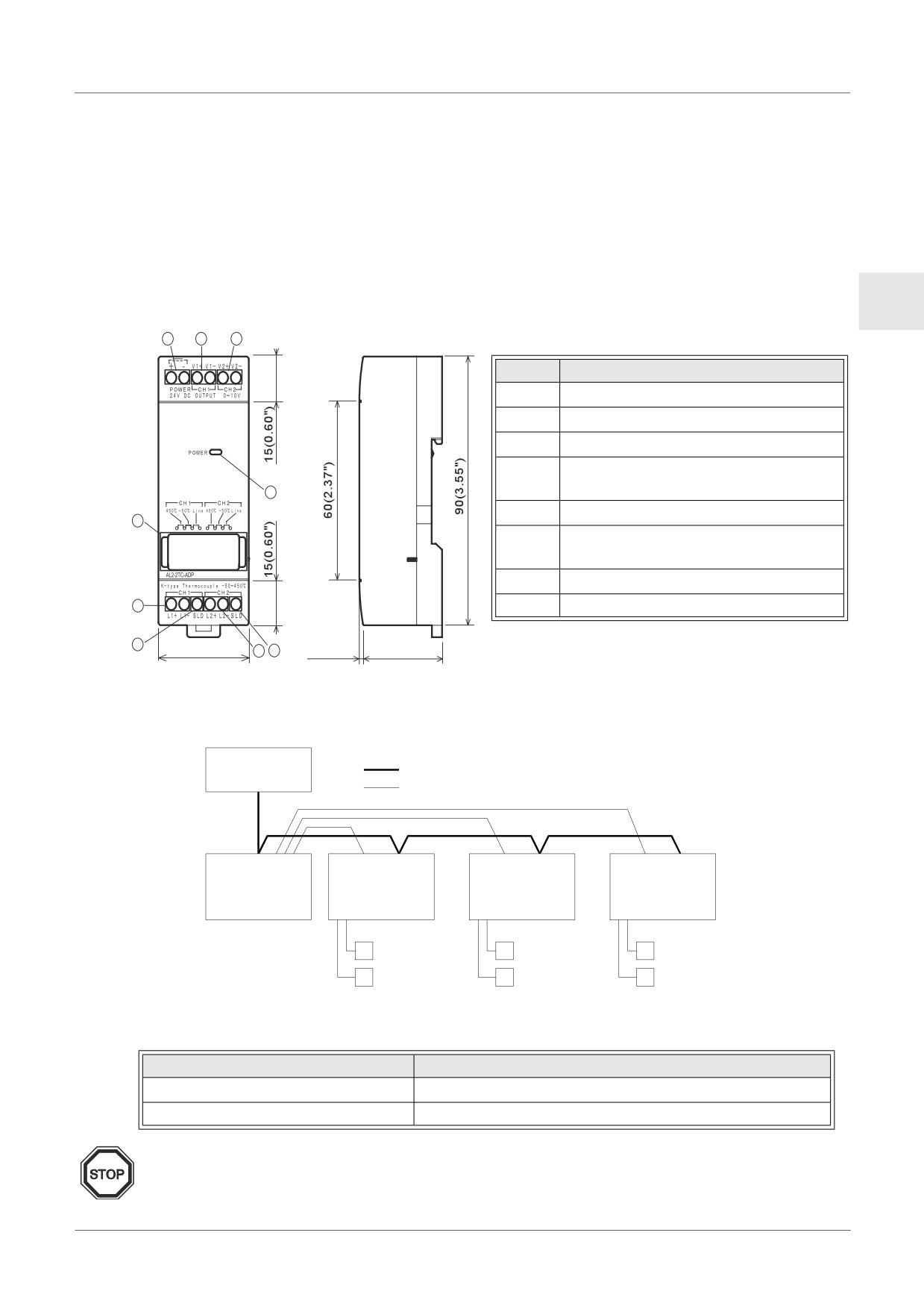
External Dimensions
Figure 13.1:External Dimensions
Unit:mm (inches)
ENG
1
2
3
Table 13.1:
Item
Description
1
+24V DC Power Supply
2
Channel 1 Voltage Output Terminal
3
Channel 2 Voltage Output Terminal
Channel 1 K-Type Thermocouple
4
Sensor Input Terminal
8
5
Shield Grounding Terminal
7
Channel 2 K-Type Thermocouple
6
Sensor Input Terminal
7
Jumper pins for adjustment
4
8
Power LED
5
35.5(1.40")
6
5
1.5(0.06")
31.0(1.23")
13.2
System Configuration
Figure 13.2:
Power Supply
DC power line
24V DC
Analog signal
AL2-14MR-D
AL2-2TC-ADP
AL2-2TC-ADP
AL2-2TC-ADP
AL2-24MR-D
K-type
K-type
K-type
Thermocouple
Thermocouple
Thermocouple
For general specifications please refer to Chapter 2.
Table 13.2: Applicable Version
PLC Type
Applicable version
α2 Series (DC Version only)
V2.00 or later
VLS Software
V2.30 or later
Note
The AL2-2TC-ADP cannot be used with the original α Series Controllers.
ENG-73
AL2-2TC-ADP 13
13.3
Specification
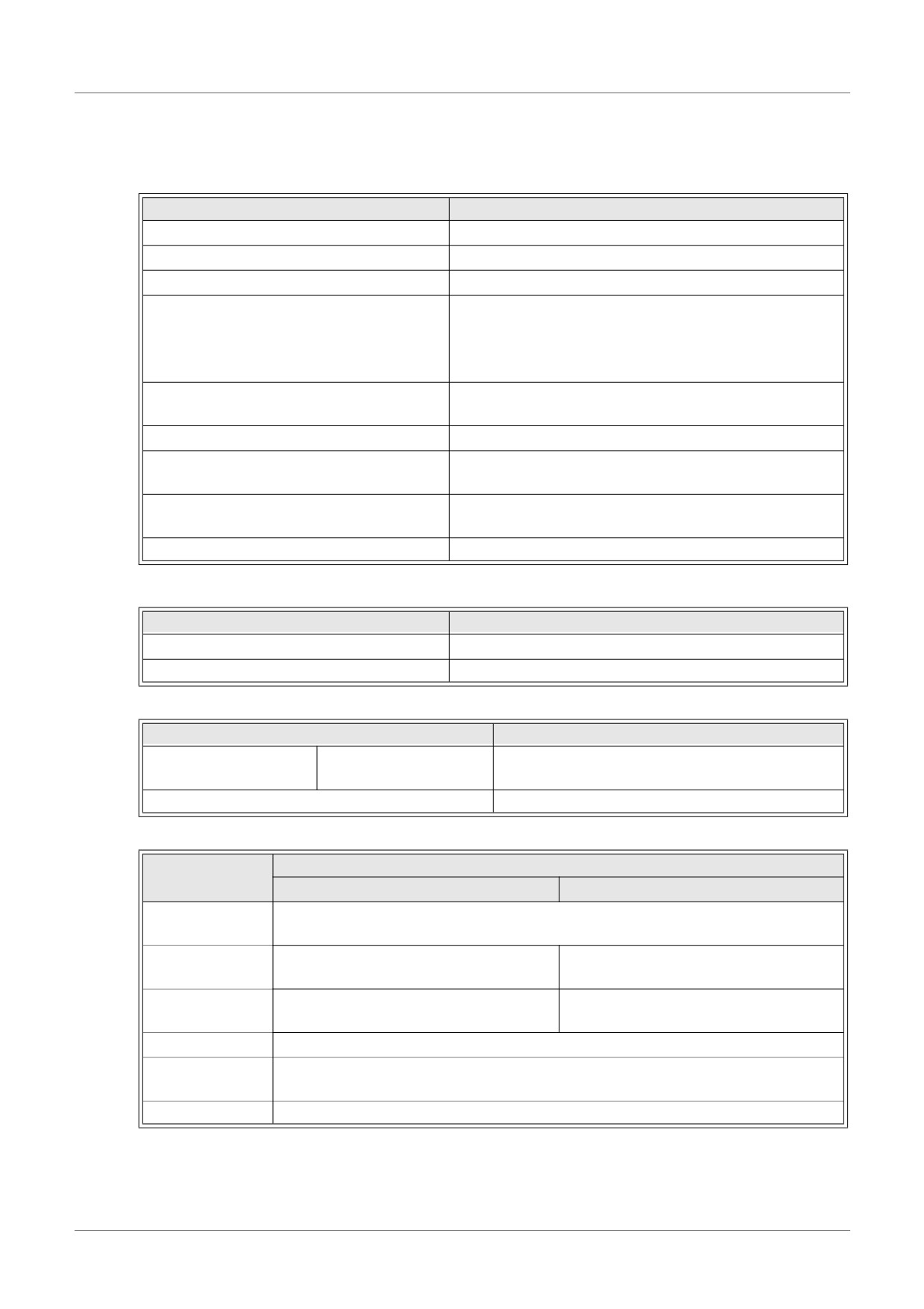
Table 13.3: General Specification
Item
Content
Operating Temperature
(-25) - 55°C / (-13) - 131°F
Storage Temperature
(-30) - 70°C / (-22) - 158°F
Humidity
35 ~ 85% Relative humidity, no condensation
Conforms to IEC 68-2-6; 10-57: Hz: 0.075mm
Constant Amplitude
Vibration Resistance - DIN Rail mounting
57-150Hz:9.8m/s2 Acceleration. Sweep Count for
X, Y, and Z: 10 times (80 minutes in each direction)
Conforms to IEC 68-2-27: 147m/s2 Acceleration, Action
Shock Resistance
Time: 11ms 3 times in each direction X, Y and Z
Noise Immunity
1000 Vpp, 1µs, 30-100Hz tested by a noise simulator
500V AC~>1min per EN60730-1 between all terminals
Dielectric Withstand Voltage
and the DIN43880 control box or equivalent.
7MΩ 500V DC EN60730-1 between all terminals and
Insulation Resistance
the DIN43880 distribution box or equivalent
Operation Ambience
To be free of corrosive gases
Table 13.4: Power Specification
Item
Content
Power Supply
24V DC +20%, -15%
Maximum Power Consumption
0.5W
Table 13.5: Adjustment Standard
Item
Content
EN61131-2: 2007
EC Directive
EMC
EN60730-1: 2011
Certification of UL/cUL
File number: E95239
Table 13.6: Hardware Specifications
Specification
Item
Centigrade (°C)
Fahrenheit (°F)
Input
Thermocouple K Type, JIS 1602-1995 (IEC 584-1 1977, IEC 584-2 1982),
Specification
Isolated Type.
Compensated
-50°C - 450°C
-58°F - 842°F
Range
±2.0% (range of all temperatures) and
±2.0% (range of all temperatures) and
Overall accuracy
±1.5% (at 25°C)
±1.5% (at 77°F)
Resolution
1°C
D/A Conversion
20.5ms
Time
Isolation Circuit
No isolation between channels (input/output) and power
ENG-74
AL2-2TC-ADP 13
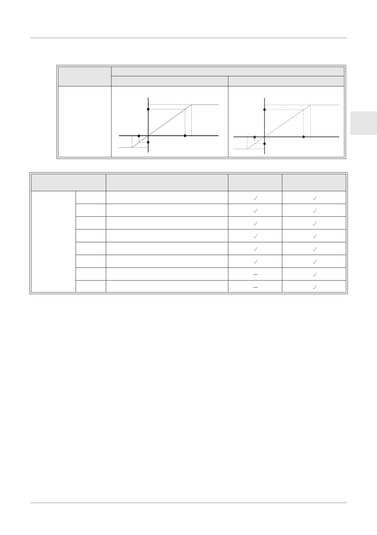
Table 13.6: Hardware Specifications
Specification
Item
Centigrade (°C)
Fahrenheit (°F)
Digital
Digital
+470
+8780
+450
+470°C
+8420
+878°F
Input
Characteristics
ENG
-50°C
-58°F
Temperature
Temperature
-50
+450°C
+842°F
-70°C
-580
(K-Type)
-94°F
(K-Type)
-70
-940
Table 13.7: Software Specification
AL2-14MR-D
Item
Content
AL2-10MR-D
AL2-24MR-D
M17
“ON” when there is a sensor defect at I01
M18
“ON” when there is a sensor defect at I02
M19
“ON” when there is a sensor defect at I03
M20
“ON” when there is a sensor defect at I04
System Bit
M21
“ON” when there is a sensor defect at I05
M22
“ON” when there is a sensor defect at I06
M23
“ON” when there is a sensor defect at I07
M24
“ON” when there is a sensor defect at I08
ENG-75
AL2-2TC-ADP 13
13.4
Wiring and Installation
13.4.1
Installation
Caution
• Do not install in areas with: excessive or conductive dust, corrosive or flammable gas,
moisture or rain, excessive heat, regular impact shocks or excessive vibration.
• The connectors must be covered to prevent contact with “Live” wires.
• The α2 Series Controller and AL2-2TC-ADP must be installed in a distribution box or a
control cabinet. The distribution box should be equipped with a cover for the AL2-2TC-
ADP module to avoid any possible foreign objects from falling inside
• Leave a minimum of 10mm (0.40") of space for ventilation between the top and bottom
edges of the AL2-2TC-ADP and the enclosure walls.
• The maximum distance between the α2 Series Controller and the AL2-2TC-ADP should
be 3m (9’10”) or less.
• The power cable should be less than 10m in length.
• A sensor with insulation rated for 500V or more should be used when the sensor is
placed near a conductive material.
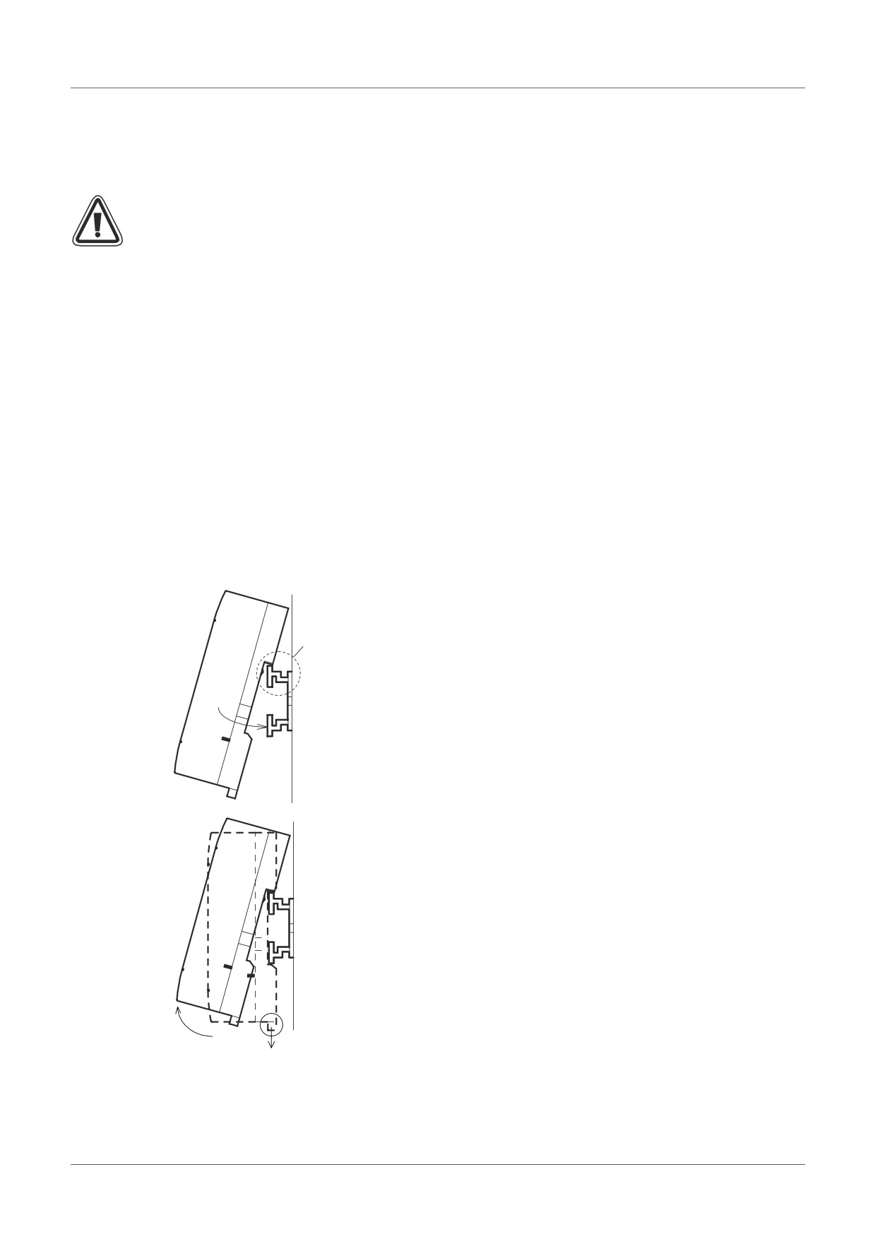
Figure 13.3: Installation
Attach
Units can be snap mounted to 35mm DIN rail (DIN
EN 50022). To release pull the spring loaded clips
away from the rail and slide the unit off and up.
(1)
1) To Attach
Align the upper side of the AL2-2TC-ADP DIN
rail mounting groove with the DIN rail (1) and
push it onto the rail (2).
(2)
2) To Release
Pull the DIN rail hook (1) and remove the AL2-
2TC-ADP.
Release
(2)
(1)
ENG-76
AL2-2TC-ADP 13
13.4.2
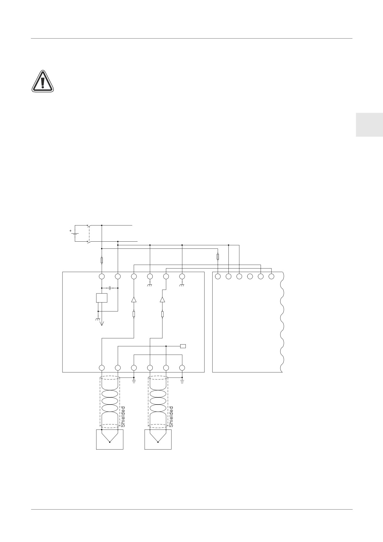
Wiring
Caution
• Please use an isolated Power supply and turn off the Power before any wiring operation
is performed.
• Input and Output cables should not be run through the same multi core cable or share
the same wire.
ENG
• Input cable (from sensor to AL2-2TC-ADP) must be less than 10m (32’81’’) and the
output cable length must be less than 3m (9’10").
• The wire should be used as a single cable or the multi core wires (can be used with a
crimp terminal) should be carefully twisted together.
Do not connect a soldered wire end to the AL2-2TC-ADP.
• To avoid damaging the wire, tighten to a torque of 0.5 - 0.6 N⋅m.
• The AL2-2TC-ADP should be adjusted for offset and gain purposes, therefore, turn off
the Power before performing the adjustment wiring.
Figure 13.4:
24V
DC
1.0A
0.5A
24+
24-
V1+
V1-
V2+
V2-
+
-
(A)
(B)
1
2
3kΩ
3kΩ
+15V
Temperature
compensation
circuit
AL2-2TC-
AL2-14MR-D/
ADP
L1+
L1-
SLD
L2+
L2-
SLD
AL2-24MR-D
Grounding
Grounding
resistance
resistance
100Ω or
100Ω or
less
less
K-type
K-type
Thermocouple
Thermocouple
ENG-77
AL2-2TC-ADP 13
13.4.3
Choosing a Temperature Scale
1) Turn on the power to the α2 controller and select “Others...” from the TopMenu.
TopMenu
C l o c kSe t
LANGUAGE
O t he r s . . .
2) Select “Analog In” from the Others... menu.
Ot her s . . .
Se r i a l Com
L i gh t T ime
Ana l og I n
3) Select “Temp. Scale” from the Analog In menu.
Ana l og I n
I
07
I
08
Temp . Sca l e
4) Choose “Celsius” or “Fahrenheit.” with the OK button.
Ana l og I n
Temp . Sc a l e
Ce l s i u s
Fah r enhe i t
Only one system of units can be selected per controller.
The values under the Calibrate menu will remain in Celsius, regardless of the system
of units that is selected for the controller, as they are the labels for the jumper pins on
the Hardware.
ENG-78
AL2-2TC-ADP 13
13.4.4
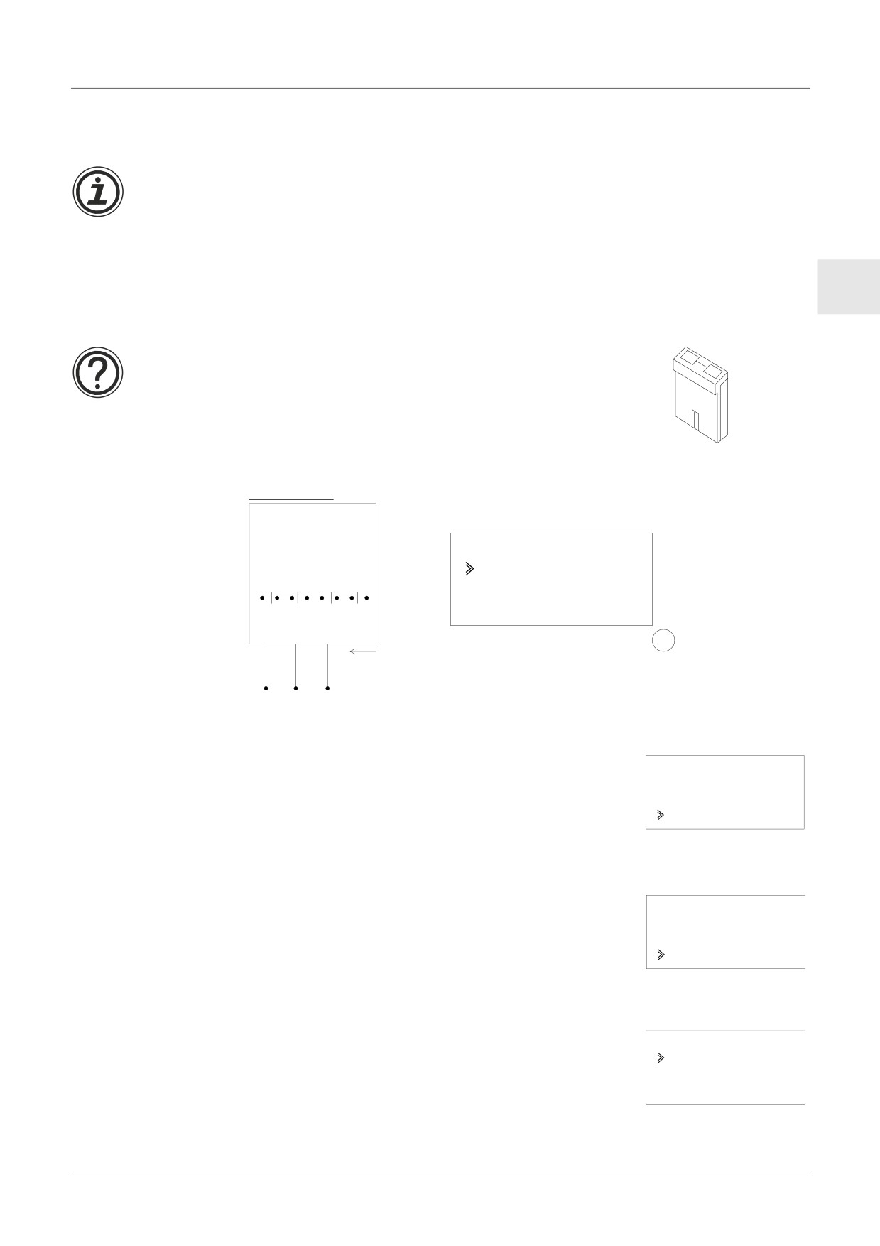
Offset Adjustment
Note
If Gain adjustment is complete, then step 3 - 7 are not needed.
1) To begin the offset calibration for channel 1, turn off the power to the α2 controller and the
AL2-2TC-ADP and remove the temperature sensor. The pins L1-, L1+ and SLD should be
left unconnected.
ENG
2) Remove the top cover from the jumper area and move the jumper to the pins labeled -50°C
as in “Hardware Setup” below.
Caution
TOP
The jumper should be installed correctly, otherwise, on occasion
electrical contact may not occur.
Bottom
Figure 13.5: AL2-2TC-ADP Offset Adjustment
Hardware Setup
Controller Setup
Ca l i b r a t e
- 50°C
-50°C
-50°C
450°C
L1+ L1- SLD
OK
3) Turn the power on and select “Others...” from the TopMenu while in Stop Mode.
TopMenu
C l o c kSe t
LANGUAGE
O t he r s . . .
4) Select “Analog In” from the “Others...” menu.
Ot her s . . .
Se r i a l Com
L i gh t T ime
Ana l og I n
5) Select the Input that is connected to the AL2-2TC-ADP module.
Ana l og
I n
I
01
I
02
I
03
ENG-79
AL2-2TC-ADP 13
6) Configure the input for temperature sensing with the AL2-2TC-ADP module by selecting
“Mode” and choosing “TC” from the following screen
I
01
I
01
Mode
Norma l
TC
PT100
7) After setting the mode to “TC”, select “Calibrate” from the Analog input settings menu.
I
01
Mode
Ca l i b r a t e
O f f s e t f i ne
8) Select “-50°C” from the Calibrate menu as in “Controller Setup” in the figure 13.5 and press
OK. There should be a confirmation message that reads “OK.” If not, refer to the Applicable
Error Checks section below. This completes the offset calibration procedure. To calibrate
the offset for channel 2, repeat the steps above replacing L1-, L1+ and SLD with L2-, L2+
and SLD respectively. When the calibration is finished, move the jumper to the “LINE” pins.
Figure 13.6: Jumper position after calibration
Hardware Setup
LINE
LINE
It is usually necessary to perform the Gain Adjustment when performing the Offset
Adjustment. See section 13.4.5 for more details.
13.4.5
Gain Adjustment
Note
If Offset adjustment is complete, then step 3 - 4 are not needed.
1) To begin the gain calibration for channel 1, turn off the power to the α2 controller and the
AL2-2TC-ADP and remove the temperature sensor. The pins L1-, L1+ and SLD should be
left unconnected.
ENG-80
AL2-2TC-ADP 13
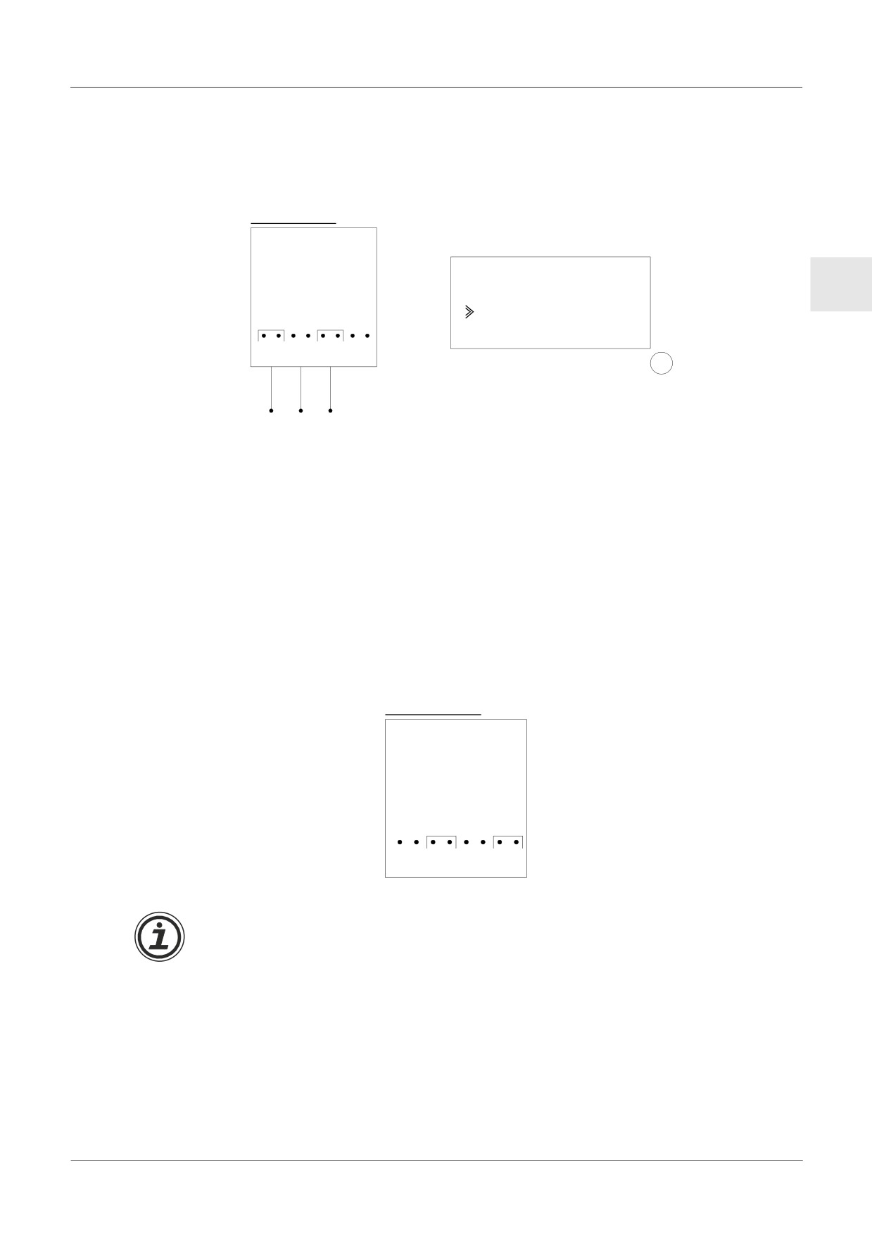
2) Remove the top cover from the jumper area and move the jumper to the pins labeled 450°C
as in “Hardware Setup” below.
Figure 13.7: AL2-2TC-ADP Gain Adjustment
Hardware Setup
Controller Setup
Ca l i b r a t e
ENG
- 50°C
450°C
450°C
450°C
L1+ L1- SLD
OK
3) Turn the power on and select “Others...” from the TopMenu while in Stop Mode.
4) After setting the mode to “TC” (See the Offset Adjustment description above.), select
“Calibrate” from the Analog input settings menu.
5) Select “450°C” from the Calibrate menu as in “Controller Setup” in the figure above. There
should be a confirmation message that reads “OK.” If not, refer to the Applicable Error
Checks section below. This completes the gain calibration procedure. To calibrate the gain
for channel 2, repeat the steps above replacing L1-, L1+ and SLD with L2-, L2+ and SLD
respectively. When the calibration is finished, move the jumper to the “LINE” pins.
Figure 13.8: Jumper position after calibration
Hardware Setup
LINE
LINE
It is usually necessary to perform the Offset Adjustment when performing the Gain
Adjustment. See section 13.4.4 for more details.
ENG-81
AL2-2TC-ADP 13
13.4.6
Fine Offset Adjust
The fine adjust should only be performed after both Gain and Offset Adjusts have
been performed.
1) From the TopMenu, select “Others...”
TopMenu
C l o c kSe t
LANGUAGE
O t he r s . . .
2) From the Others... menu, select “Analog In”
Ot her s . . .
Se r i a l Com
L i gh t T ime
Ana l og I n
3) From the Analog In menu select an input that is configured for TC input.
Ana l og I n
I
01
I
02 : PT100
I
03 : TC
4) Select “Offset fine” from the Analog Input settings menu.
I
03
Mode
Ca l i b r a t e
O f f s e t f i ne
5) Using the + and - buttons, enter a value from -31°C to 31°C (-55.8°F to 55.8°F).
Press the OK button when finished.
I
03
O f f s e t f i ne
0 °C
ENG-82
AL2-2TC-ADP 13
13.4.7
Applicable Error Checks
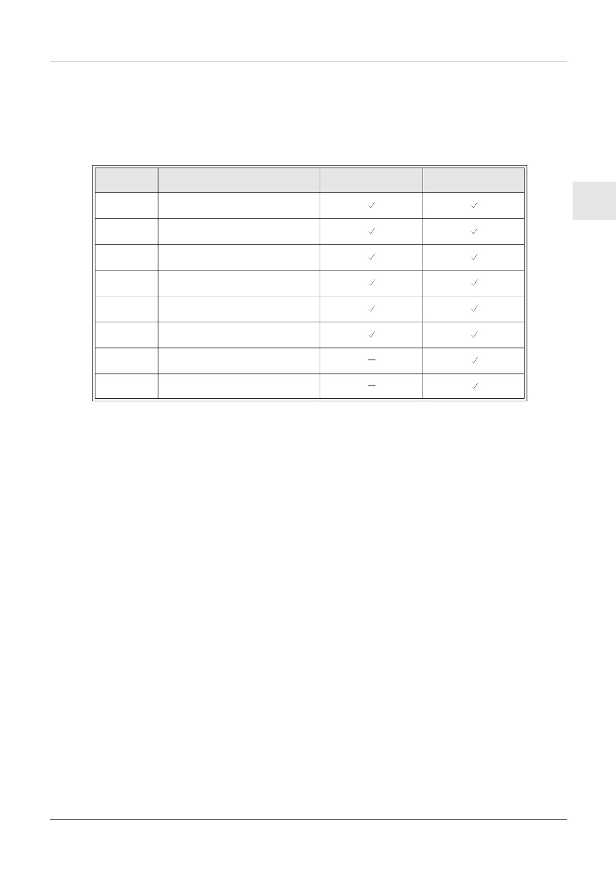
In the event that the input voltage is greater than 11 V or equal to 0V the following system flags
will be set.
Table 13.8:
AL2-14MR-D
AL2-10MR-D
AL2-24MR-D
0: Normal
M17
ENG
1: Defect at I01
0: Normal
M18
1: Defect at I02
0: Normal
M19
1: Defect at I03
0: Normal
M20
1: Defect at I04
0: Normal
M21
1: Defect at I05
0: Normal
M22
1: Defect at I06
0: Normal
M23
1: Defect at I07
0: Normal
M24
1: Defect at I08
- If the flags in the table above are activated, check that:
• a sensor is connected
• there is not a break in the sensor connection
• the temperature is not greater than the specified limit
• power is being supplied to the AL2-2TC-ADP.
- If the “Error” message appears instead of “OK” while offset/gain calibration, check that:
• The power is being supplied to the AL2-2TC-ADP.
• The AL2-2TC-ADP is connected to α2 correctly.
• The input, which connects the AL2-2TC-ADP is selected for calibration.
• The AL2-2TC-ADP inputs are left unconnected.
• The jumpers on AL2-2TC-ADP is either placed on the “-50°C” position or the “450°C”
position.
• The calibration menu entry related to the jumper position is selected (“-50°C” or “450°C”).
ENG-83
Key, System Bit and Function Block Lists 14
14.
Key, System Bit and Function Block Lists
14.1
Key Lists
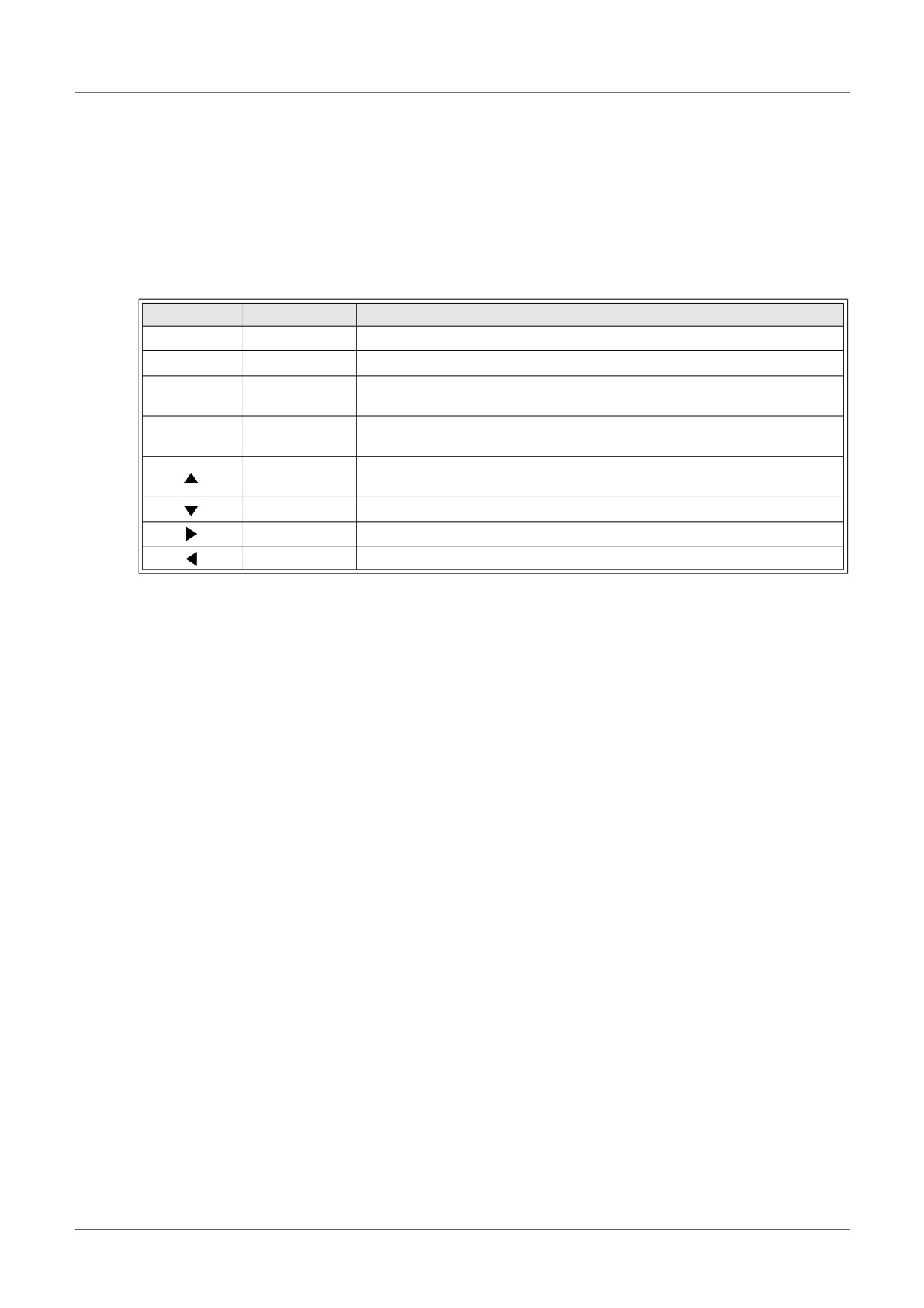
The following table is the keys to use operation in the Menu and user program. Further
information can be found in α2 Programming Manual.
Table 14.1: Operation Key Lists
Key Name
Key Number
Description
OK
K01
Acceptance of data entry, menu options, program choices
ESC
K02
Cancel current operation, move to higher screen or menu
Connect function blocks, move to higher numbered blocks, increment
+
K03
values
Disconnect function blocks, move to lower numbered blocks,
-
K04
decrement values
Scroll to higher number numbered items (keys, FB, Inputs, Outputs,
K05
etc.)
K06
Scroll to lower numbered items (keys, FB, Inputs, Outputs, etc.)
K07
Move to the right on the LCD display, FB program or Jump command
K08
Move to the left on the LCD display, FB program or Jump command
ENG-84
Key, System Bit and Function Block Lists 14
14.2
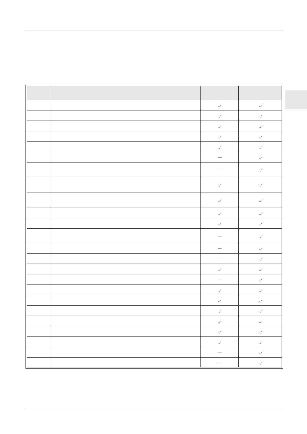
System Bit Lists
There is the system bit controlled by system and the control bit to control from user program.
14.2.1
System Bit Lists
Table 14.2: System Bit Lists
System
AL2-14MR-*
Description
AL2-10MR-*
Bit
AL2-24MR-*
ENG
M01
Always “ON”
M02
Always “OFF”
M03
Alternate - 0.5 seconds “ON”, 0.5 seconds “OFF”
M04
“ON” when Real Time Clock data error occurs
M05
“ON” when Summer time schedule is activated
M06
“ON” when communication Error of AS-interface occurs
“ON” when communication Error by AS-interface power failure
M07
occurs
ON when turn Stop mode turns to Run mode in the α2 Series.
M08
The ON signal acts as a pulse output and then turns OFF.
OFF when turn Stop mode turns to Run mode in the α2 Series.
M09
The OFF signal acts as a pulse output and then turns ON.
M10
“ON” during DCF77 decoding.
M11
Pulses “ON” when DCF77 finishes decoding without an error.
“ON” when CD (DCD) signal is turned ON (receiving CD signal
M12
from modem)
M13
“ON” when it is possible to access the GSM network.
M14
“ON” when the α2 series is accessed via GSM.
M15
“ON” when DCF77 decoding with an error.
M16
“ON” when external power for the AL2-2DA board is ON.
M17
“ON” when there is a sensor defect at I01
M18
“ON” when there is a sensor defect at I02
M19
“ON” when there is a sensor defect at I03
M20
“ON” when there is a sensor defect at I04
M21
“ON” when there is a sensor defect at I05
M22
“ON” when there is a sensor defect at I06
M23
“ON” when there is a sensor defect at I07
M24
“ON” when there is a sensor defect at I08
ENG-85
Key, System Bit and Function Block Lists 14
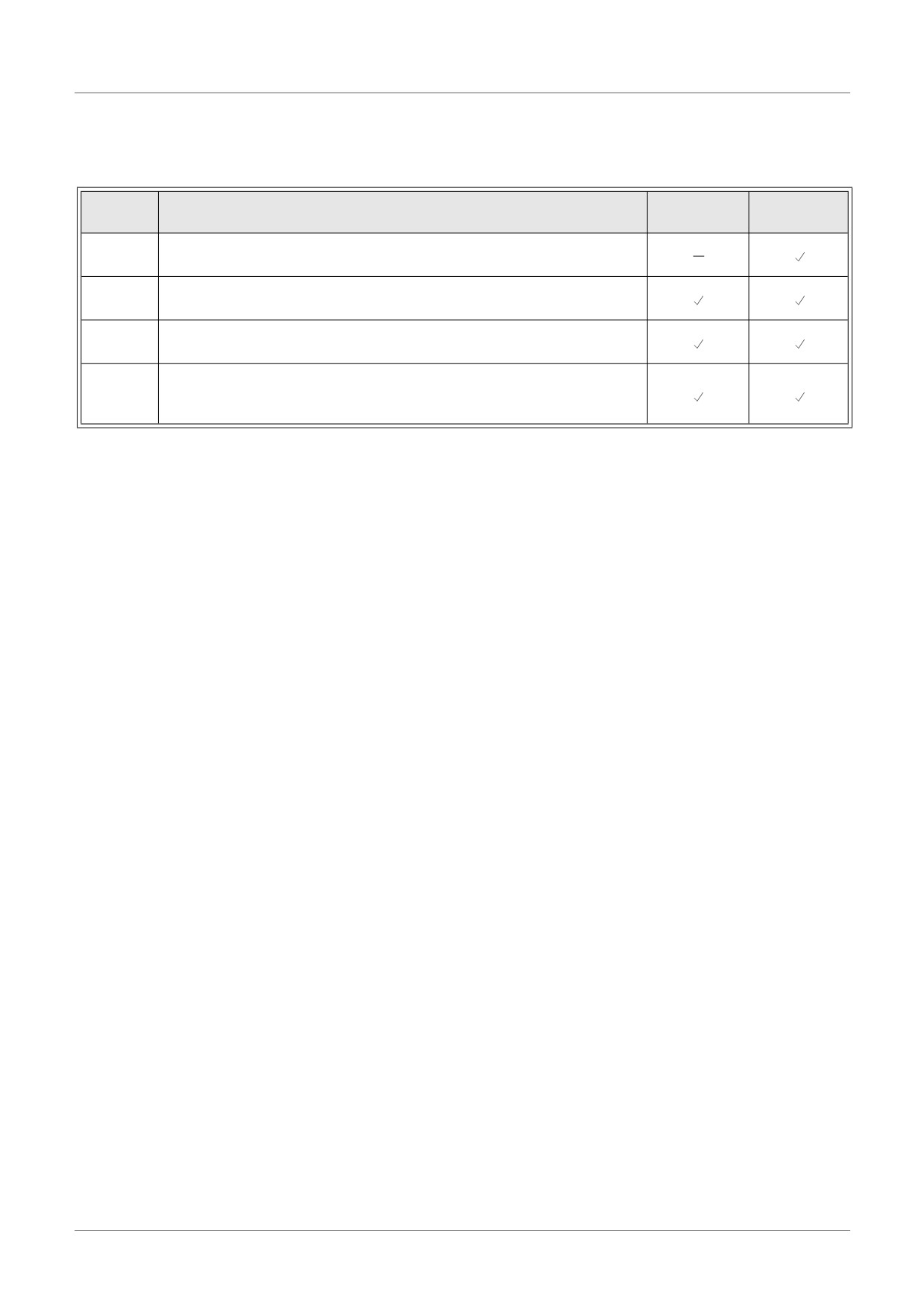
14.2.2
Control Bit Lists
Table 14.3: Control Bits
Control
AL2-14MR-*
Description
AL2-10MR-*
Bit
AL2-24MR-*
ON: Disconnected to AS-interface network
N01
OFF: Connect to AS-interface network
ON: The back light is “OFF” in LCD.
N02*1
OFF: The back light is controlled by the “Light Time” setting in Menu.
ON: The back light is “ON” in LCD.
N03*1
OFF: The back light is controlled by the “Light Time” setting in Menu.
ON: The user screen is controlled by the setting of “Display
N04
Manager” with AL-PCS/WIN-E.
OFF: The user screen is controlled by user program.
*1 When both N02 and N03 are ON and hence the back light is “ON” because N03 is given
the priority.
ENG-86
Key, System Bit and Function Block Lists 14
14.3
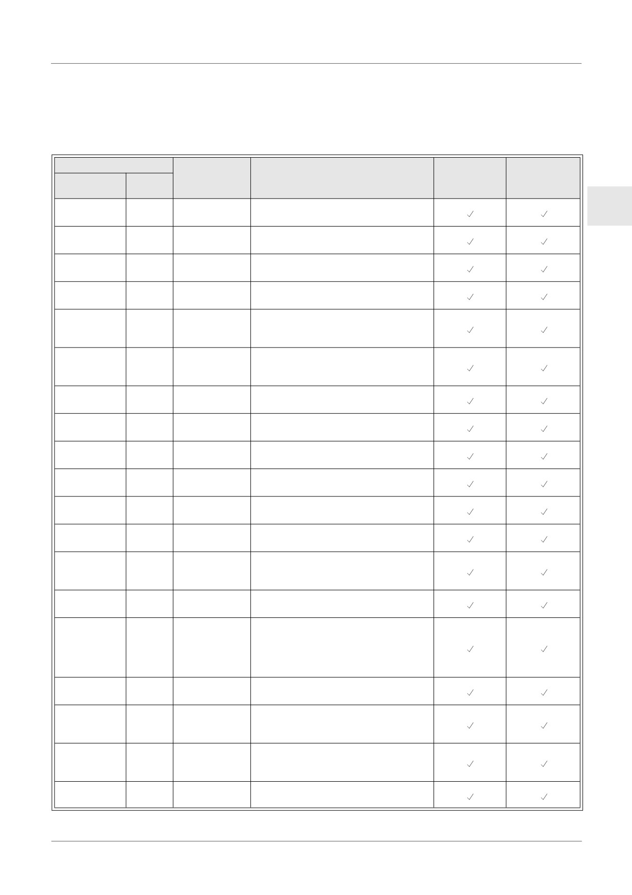
Function Block Lists
Further information for function blocks can be found in the α2 Series Programming Manual.
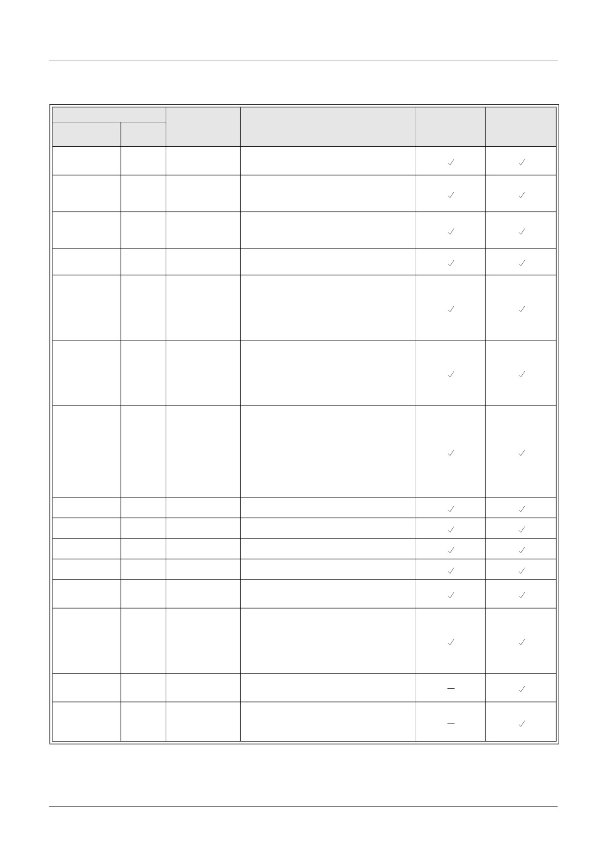
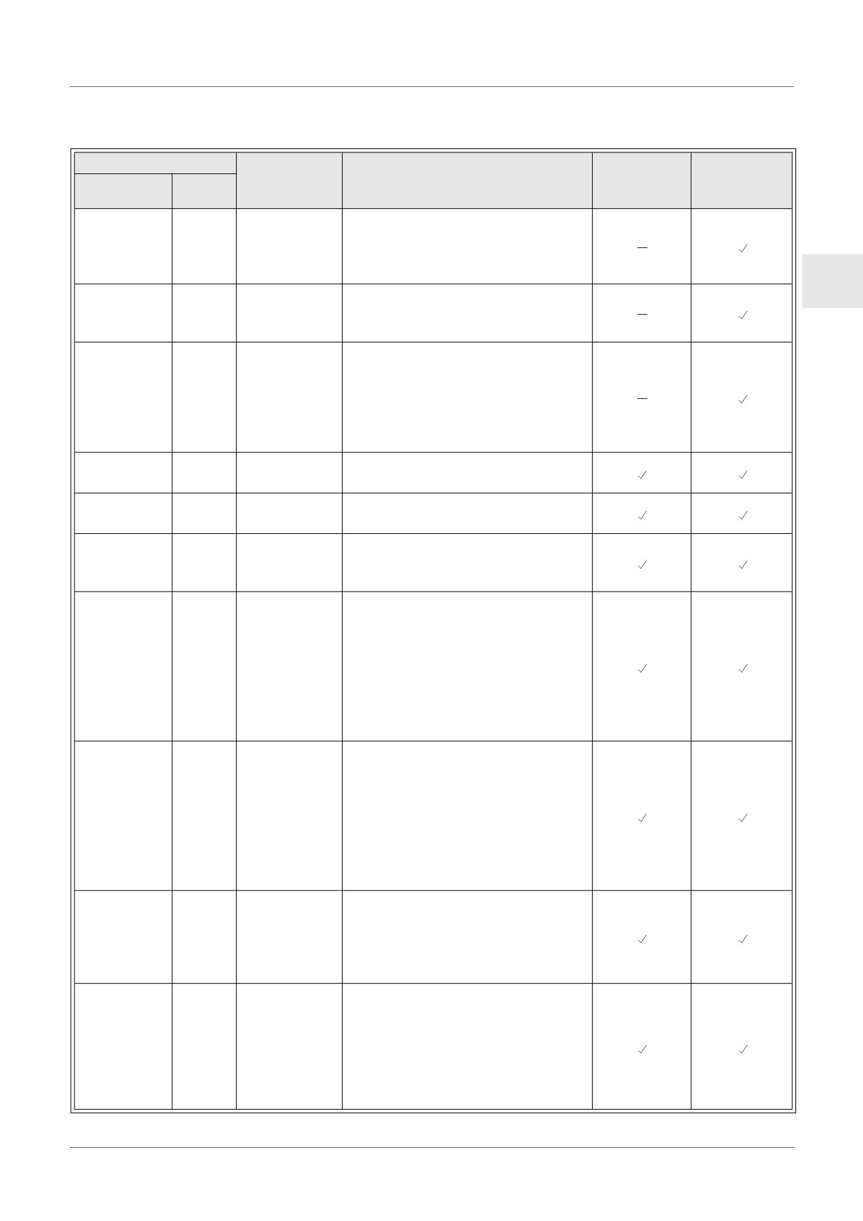
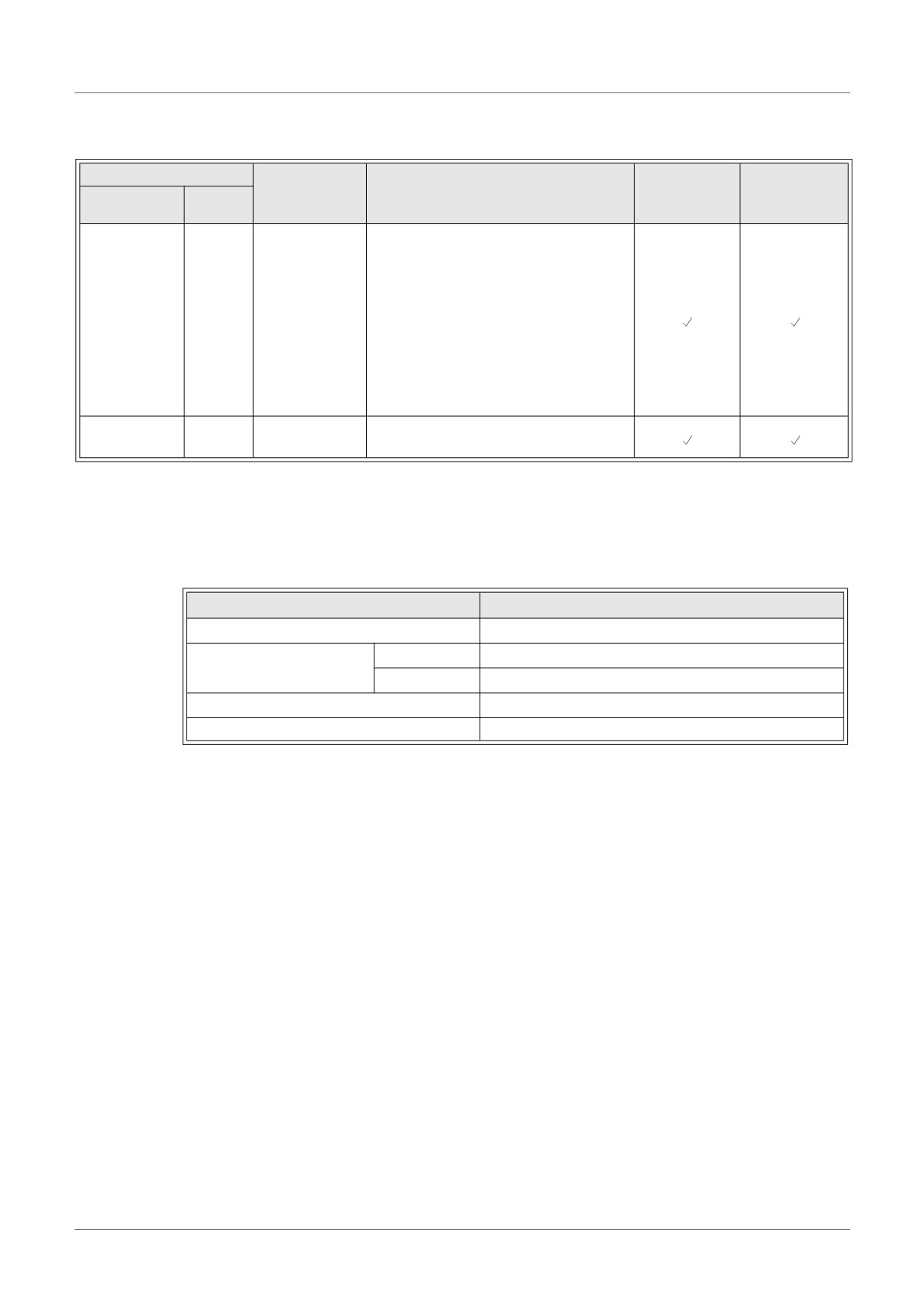
Table 14.4: Function Block Lists
Function Block
Memory
AL2-14MR-*
Consumption
Description
AL2-10MR-*
Name
Symbol
AL2-24MR-*
(Byte)
Output ON when all Inputs are ON,
ENG
AND
AND
19
Unused inputs considered ON
Output ON when at least one input
OR
OR
19
ON, Unused inputs considered OFF
Inverts a signal; changes an OFF to
NOT
NOT
10
an ON and vice versa
Exclusive OR; Output ON when only
XOR
XOR
13
One of Two Inputs is ON
Not AND; Output OFF only when all
NAND
NAND
19
Inputs ON, Unused inputs
considered ON
Not OR; Output OFF when at least
NOR
NOR
19
one Input is ON, Unused inputs
considered OFF
Logic equation using AND, OR,
Boolean
BL
*1
XOR, NOT
Latch a relay in SET or RESET
Set/Reset
SR
14
position, give Set or Reset priority
Send a Pulse on the Rising, Falling,
Pulse
PL
10
or both Edges
Output alternates turning ON or OFF
Alternate
AL
13
with each input pulse
Delay a signal on the Rising, Falling,
Delay
DL
19
or both Edges
Send a single pulse; Time or Input
One Shot
OS
17
signal based, Reset pin available
Send a pulse train; ON/OFF times,
Flicker
FL
19
repetitions, duration, or continuous
operation
Use the RTC to turn output ON/OFF;
Time Switch
TS
*2
Calendar or weekly schedule
Use the RTC to turn output ON/OFF;
Calendar or weekly schedule
Time Switch
TSm
*2
The function block can be setup from
Maintenance
the TopMenu "Parameter" via the
front panel keys.
Count upwards on pulses, can reset
Counter
CN
16
at a signal
Count upward or downward, Set a
Up/Down
UD
22
Preset Value for the Output to come
Counter
ON
Compare two values for
Compare
CP
17
<,>,=,<=,>=,<> (Analog, Direct Set,
or FB values)
Manipulate Analog Values; y = A/B∗x
Offset Gain
OG
22
+ C; Set High and Low Limit Values
ENG-87
Key, System Bit and Function Block Lists 14
Table 14.4: Function Block Lists
Function Block
Memory
AL2-14MR-*
Consumption
Description
AL2-10MR-*
Name
Symbol
AL2-24MR-*
(Byte)
Display User Screen (messages or
Display
DP
*3
data) on the LCD display
Compare a value to a range of
Zone
ZC
20
values (Analog, Direct Set, or FB
Compare
values)
Turn an Input ON at the High Value
Schmitt
ST
19
and OFF at the Low Value (or vice
trigger
versa)
Records the accumulated time a
Hour Meter
HM
19
signal has been ON
The signal input frequency (On/Off)
is measured for a set length of time.
Speed Detect
SPD
25
The frequency is compared to a
value range and the Output is turned
ON/OFF according to the result.
A continuous pulse train is output
when this function block is driven.
Pulse Width
PWM
16
The characteristics of the pulse are
Modulation
defined as; Pulse duty (Direct set,
Analog, FB values), cycle time.
Output alternates turning ON or OFF
with each input pulse. The last output
status is kept when the power supply
Retentive
RAL
13
is cycled OFF and ON.
Alternate
However, last output status is lost
when the α2 series is placed in the
Stop mode.
Addition
ADD
20
y = A + B
Subtraction
SUB
20
y = A - B
Multiplication
MUL
20
y = A × B
Division
DIV
20
A ÷ B = q, r (quotient and remainder)
Equation using +, −, ×, ÷, % and the
Calculation
CAL
*4
selected data.
Shift operation; When “SFT” signal is
input, last “I” signal status is output.
Shift
SFT
19
When using 8 bit shift operation,
“Shift” function block should be
continued 8 times.
The contents of an LCD screen is
GSM SMS
SMS
*5
sent as an SMS message.
Short
Message
SMR
*7
Output change by Short Message
Receiving
ENG-88
Key, System Bit and Function Block Lists 14
Table 14.4: Function Block Lists
Function Block
Memory
AL2-14MR-*
Consumption
Description
AL2-10MR-*
Name
Symbol
AL2-24MR-*
(Byte)
Short
Output change by Short Message
Message
The function block can be setup from
SMRm
*7
Receiving
the TopMenu "Parameter" via the
Maintenance
front panel keys.
ENG
Calling Line Identification
Call Detect
CD
30
Presentation (CLIP) Phone number
detection
Calling Line Identification
Presentation (CLIP) Phone number
Call Detect
detection
CDm
30
Maintenance
The function block can be setup from
the TopMenu "Parameter" via the
front panel keys.
Random One
The random length single pulse is
ROS
19
Shot
output.
Delayed One
After a delay time, send a single
DOS
20
Shot
pulse
After a delay time, output alternates
Delayed
DAL
16
turning ON or OFF with each input
Alternate
pulse
Latch a relay in SET or RESET
position, give Set or Reset priority.
The last output status is kept when
Retentive
the power supply is cycled OFF and
RSR
14
Set/Reset
ON.
However, last output status is lost
when the α2 series is placed in the
Stop mode.
The PID Function Block is the α2
implementation of PID, a control
method used to obtain stable control
Proportional
over a system variable. It is a
PID
52
Integral Gain
equipped with an Auto-tuning
function, which automatically adjusts
the Function Block parameters for
the specific application.
The Analog Output function takes a
digital value input and delivers a
Analog
AO
17
corresponding analog voltage or
Output
current to a selected channel on the
AL2-2DA module.
Control which Display screen
appears on the LCD. This function
block can only be set in the AL-PCS/
Control
CDP
*6
WIN-E software.
Display
When control bit N04 is ON, it
possible to control the displayed
User Screen.
ENG-89
Key, System Bit and Function Block Lists 14
Table 14.4: Function Block Lists
Function Block
Memory
AL2-14MR-*
Consumption
Description
AL2-10MR-*
Name
Symbol
AL2-24MR-*
(Byte)
This CONNECT function block is an
internal FB used to show the memory
used by the system bits, the bits for
AS-interface, and the operation keys.
No function block appears on screen
Connect
_B
10
or shows as being used in the
“Memory Configuration Usage”
dialog box, the purpose is only to
calculate the memory that is used by
the bits listed above.
System
Control external device through
Out
10
Outputs
relays and transistors.
*1
Number of bytes used = 19 + 1 × (Characters in equation)
*2
Number of bytes used = 8 + 4 × (Number of time switches)
*3
Number of bytes used is decided by the displayed item.
Table 14.5:Displayed Item and number of bytes used
Displayed Item
Number of bytes, α2 Series
Characters
16 + 1 × (Each character displayed)
Value
17
Analog, FB value
Graph
23
Time, Date
14
Time Switch
17
*4
Number of bytes used = 30 + 1 × (Characters in equation)
*5
Number of bytes used = 12 + 1 × (Characters in E-Mail address)
*6
Number of bytes used = 32 + 3 × (Number of screen)
*7
Number of bytes used = 37 + (Number of characters of setup commands)
ENG-90
Diagnostics 15
15.
Diagnostics
Caution
• Do not touch the terminal while energized. This might cause an equipment malfunction
or an electric shock.
Caution
ENG
• Supply correctly rated power.
When a power supply different from the ratings is supplied, this product might be
damaged or cause a fire.
• Connect “L (Live)” of the power supply to “L terminal” in the main unit, and connect “N
(Neutral)” to “N terminal” in the main unit correctly when wiring the AC power supply.
Faulty wiring will cause an electrical shock, damage to the controller, or a fire.
• Connect the “L (Live)” wire of the power supply to the input terminal of the AC unit.
• Connect the “+” of the power supply connect to the “+ terminal” in the main unit, and
connect the “-” of the power supply to the “- terminal” when wiring the DC unit.
Faulty wiring will cause an electrical shock, damage to the controller, or a fire.
Notes on use
• The α2 Series controller must be used with either the memory cassette, communication
cable, or connector cover installed. Otherwise, the exposed socket can cause damage to
the controller or an electric shock to the operator.
• Use the expansion module or the connector cover while power is supplied to the α2
series controller.
Improper equipment installation can cause damage to the controller or an electric shock.
ENG-91
Diagnostics 15
15.1
Input Status Error
Place the α2 controller in the Stop mode. Cycle the power to the equipment connected to the
input terminals and check if the input status is displayed correctly. If it is not correctly
displayed, check the points below.
Further information about the status display can be found in the α2 Programming Manual.
Notes on use
Do not connect a wire with a soldered end to an α2 series terminal due to poor contact and
the possibility of the wire shearing.
1) Check the wiring for the power supply and the inputs.
2) Check if the equipment used for the inputs corresponds to the specification in section 2.3 in
this manual.
15.2
Output Status Error
Place the α2 controller in the Stop mode. Force the outputs ON/OFF and check the operation
of the outputs. Check that the program is written to perform per the desired results.
Further information can be found about the force ON/OFF operation in the α2 Programming
Manual.
Notes on use
Perform the forced ON/OFF operations only after thoroughly checking that it is safe to do
so. Damage to the machine or controller or a safety issue could arise if the forced ON/OFF
is performed inappropriately.
If proper precautions are not taken, damage to the equipment or machine failure may occur.
1) Check the wiring for the power supply and the outputs.
2) Check if the equipment used for the outputs corresponds to the specification in section 4.4
in this manual.
ENG-92
Diagnostics 15
15.3
TOP MENU is not Displayed
The menu key should be operated to access the Top Menu. Push the keys “OK” and “ESC” at
the same time. If the menu call key is not set, use either the programming software to the Stop
mode or do the forced stop operation.
The Top Menu cannot be accessed from the keys. However, by cycling the power supply and
pressing the “OK + ESC” keys simultaneously during the power up, the Top Menu will appear.
ENG
Caution
Perform the forced stop operation only after thoroughly checking that it is safe to do so.
Damage to the machine or controller or a safety issue could arise if the forced ON/OFF is
performed inappropriately.
If proper precautions are not taken, damage to the equipment or machine failure may occur.
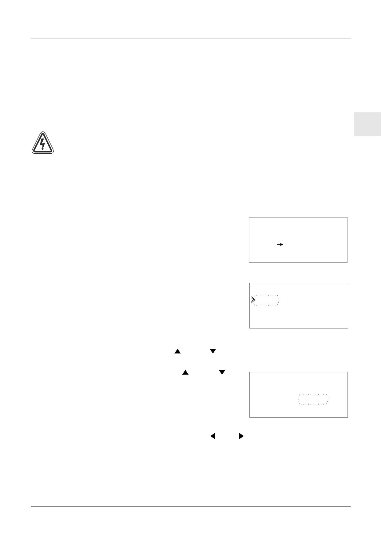
Forced Stop Operation
1) Turn the α2 series power supply off.
2) Turn the power ON again while pushing the “OK” and
“ESC” keys simultaneously.
The screen at right is displayed.
Run
The option to place the controller in Stop mode will be
St op
available for approximately five seconds. Press the
“OK” key to enter the Stop Mode. If no key is pressed,
the controller will default back into the Run mode.
3) Push “ESC” key.
The “Top Menu” shown at right is displayed.
TopMenu
Run
Pa r ame t e r
P r ogEd i t
ENG-93
Diagnostics 15
15.4
Cannot enter Run Mode.
When the α2 series will not switch to Run mode, check the following.
1) The message “Input Error” or “Output Error” is displayed on the screen.
The program included in the memory cassette has more points of input and/or output than
is allowed in the controller body.
a) When making the program with the programming software.
The content of the program and the model are checked with the programming software.
Write the program to the α2 series controller and do not use a memory cassette.
b) When making the program with the α2 series front panel keys.
Remove the memory cassette, and make the program again.
c) Install the memory cassette in the α2 series of 24 point type.
d) Write the program in an α2 series of the same type in which the program will be used.
2) The program data has an error.
When the program cannot be displayed with “ProgEdit” in “TopMenu”, it is possible that the
program data was damaged. Switch from “TopMenu” to the Run mode after deleting the
program.
a) The program again and switch to Run mode.
b) Consult a Mitsubishi Distributor when unable to switch to the RUN mode.
15.5
Incorrect Clock Data
Confirm the following item.
1) The time data is lost.
When approximately 20 days or more (25°C.) have passed since power was supplied to the
α2 series, the time data is lost. In this case, the time data should be set.
Further information about setting the time data can be found in the α2 Programming
Manual.
2) There are keep advancement by the time data and keep a delay.
The accuracy of the time data is ±5 seconds a day. Use the time correction function when
the time data error increases.
Further information about setting the time correction function can be found in the α2
Programming Manual.
15.6
The “?” appears on the Display
The “?” mark is displayed when an unacceptable key is
pressed according to the screen data. Confirm the
acceptable options and press the appropriate key.
?
ENG-94
Diagnostics 15
15.7
Cannot Use an Operation Key
Check the movement of the operation keys according to the following procedures when the α2
series will not accept a key operation. If the steps outlined in instructions (1) - (5) below can be
performed, the keys are operating properly. Please check if the key(s) are used in the program.
1) Place the controller in the Stop mode. Consult a Mitsubishi Distributor when the Stop mode
cannot be entered.
ENG
Caution
Perform the forced stop operation only after thoroughly checking that it is safe to do so.
Damage to the machine or controller or a safety issue could arise if the forced ON/OFF is
performed inappropriately.
If proper precautions are not taken, damage to the equipment or machine failure may occur.
Forced Stop Operation
a) Turn the α2 series power supply off.
b) Turn the power ON again while pushing the “OK” and
“ESC” keys at same time.
The screen at right is displayed for 5 seconds.
Run
The option to place the controller in Stop mode will be
St op
available for approximately five seconds. Press the
“OK” key to enter the Stop Mode. If no key is pressed,
the controller will default back into the Run mode.
c) Push the “ESC” key.
The “Top Menu” shown at right is displayed.
TopMenu
Run
Pa r ame t e
r
P r ogEd i t
2) Scroll through the Top Menu with “
” key or “
” key.
Consult a Mitsubishi distributor when you cannot scroll.
3) Move the cursor to “ClockSet” with “
” key or “
” key,
and push the “OK” key twice.
Cl o ckSe t
The “ClockSet” screen at right is displayed.
mm / d d / y y y y
Consult a Mitsubishi distributor when it is not displayed.
09 / 06 / 2001
13 : 55
Thu
4) Try to change the month/year data using the “
” key, “
” key, “+” key and “-” key.
Consult a Mitsubishi distributor when editing is not possible.
ENG-95
Diagnostics 15
5) Push the “ESC” key.
The screen at right is displayed and the operation of (4)
C l o ckSe t
is invalidated.
C l o ckSe t
Consult a Mitsubishi Distributor when the correct screen
Co r r e c t
is not displayed.
GMT Zone
15.8
Incorrect LCD display
Check the following items.
1) The character is displayed in reverse and the entire screen is black.
Consult a Mitsubishi Distributor when the above error occurs. The α2 controller display has
been damaged.
2) An Unexpected Display Configuration is Shown
When the display does not appear as expected, please check the following points in the
program.
a) Adjust the position where each display function begins. Two separate displays might
have an overlapping display area that causes the undesired result.
b) The character fails to display
- Check if the input pin to the Display Function Block is On.
- Check whether there is a conflict with another display.
15.9
Memory Cassette Is Not Working Correctly
Check the following items when the memory cassette is not recognized or the cassette transfer
functions are not functional.
Notes on use
• Use the memory cassette, the telecommunication cable, or the connector cover while
power is supplied to the α2 series controller.
Improper equipment installation can cause damage to the controller or an electric shock.
1) The memory cassette must be installed correctly, refer to section 6.1 for the proper
installation procedure.
2) The message “ProtectSW Error” is displayed.
The data protection (ProtectSW) is set.
Refer to the α2 Programing Manual for the procedure to unlock this setting.
3) The message “Password Error” is displayed.
The password is set. Try again after disabling the password.
Refer to the α2 Programing Manual for the procedure to dibble the password.
The “ProgClear” option can delete the password, program, and all Top Menu settings. The
controller will return to the factory default settings.
Refer to α2 Programing Manual for the procedure to use the “ProgClear” operation.
ENG-96
Diagnostics 15
15.10
Cannot Communicate with the AS-interface Master Module
Check the following items.
Notes on use
• Use the expansion board or the connector cover while power is supplied to the α2 series
controller.
ENG
Improper equipment installation can cause damage to the controller or an electric shock.
1) Check whether AS-interface power supply is adequate.
2) Check that the control bit N1 is Off. Use one of the two methods below to change its status
if required.
a) When not using it in the program
Force the status to Off, refer to α2 Programing Manual for the Force On/Off procedure
b) When using it by the program
Change the program or manipulate the inputs so that the control bit N1 turns Off.
3) Check that the slave address is correct.
Set the slave address from the AS-interface master module.
Refer to the manual of section 9.4.1 and the AS-interface master module for the address
setting method.
a) Another slave’s address and the AL2-ASI-BD's address overlap.
Set the address so that there is no conflict.
b) Slave address is 0.
Set a valid slave address from the AS-interface master module.
4) AL2-ASI-BD is not an active slave on the master module side.
Check the setting of the master module.
Refer to the manual of the AS-interface master module for the confirmation method.
ENG-97
Diagnostics 15
15.11
Cannot Communicate with AL-PCS/WIN-E.
Check the following items.
Notes on use
Use the memory cassette and the communication cable or the connector cover while
installed without fail.
It causes the electric shock and the breakdown.
1) Check cable (AL-232CAB) connection.
Refer to section 7.2 for the connection method.
2) Check the power supply supplied to the α2 series.
Refer to section 4 for the wiring for the power supply.
Moreover, refer to section 2.2 for the specification of the power supply.
3) Check whether the COM port of the personal computer which has connected a setup and
cable (AL-232CAB) of the “communication port” set up by programming software is in
agreement.Match it when not matching. Match it.
4) When it is remotely maintained with a modem
a) Check whether a setup of the modem by the side of α2 series is correct.
Refer to α2 programming manual and section 7.3 for the setting of the modem
connected to the α2 series side.
b) Check the connection of cable made by customer.
For the connection of cable, refer to section 7.3.2.
c) Check the setting of the modem on the programming software side.
Check whether the disk for a setup of modem attachment is installed correctly.
ENG-98
GER
α2-Steuerung
HARDWARE-HANDBUCH
α2-Steuerung
Vorwort
• Dieses Handbuch enthält Texte, Abbildungen und Erläuterungen, die den Leser bei der korrekten
Programmierung und beim Betrieb einer α oder α2-Steuerung unterstützen.
• Vor der Installation oder dem Betrieb einer α/α2-Steuerung sollte dieses Handbuch gelesen und verstanden
worden sein.
• Falls bei der Installation einer α- oder α2-Steuerung Fragen auftreten, wenden Sie sich bitte an eine
anerkannt ausgebildete Elektrofachkraft, die mit den geltenden elektrotechnischen Bestimmungen vertraut
ist.
• Bei Fragen zur Programmierung oder zum Betrieb einer α/α2-Steuerung wenden Sie sich bitte an Ihren
MITSUBISHI Vertriebspartner.
• Wenn das Gerät in einer nicht vom Hersteller angegebenen Weise verwendet wird, kann der Schutz des
Geräts beeinträchtigt sein.
• Unter keinen Umständen übernimmt Mitsubishi Electric die Haftung oder die Verantwortung für Schäden, die
sich aus der Installation oder dem Betrieb dieser Geräte ergeben.
• Alle Beispiele und Abbildungen in diesem Handbuch sollen nur zum besseren Verständnis des Textes
beitragen. Die korrekte Funktion kann nicht garantiert werden. Mitsubishi Electric übernimmt keine
Verantwortung, wenn diese Beispiele zum Betrieb der Geräte verwendet werden.
• Für Anwendungen, bei denen eine hohe Verfügbarkeit der Steuerungen erforderlich ist oder bei denen
lebensbedrohende Situationen auftreten können, setzen Sie sich bitte mit Ihren MITSUBISHI
Vertriebspartner in Verbindung.
• Der Inhalt dieses Handbuchs kann jederzeit ohne besondere Hinweise geändert werden.
Dieses Handbuch berührt keine gewerblichen Schutzrechte oder irgendwelche anderen Rechte
und keine Patentrechte. Mitsubishi Electric kann nicht für die Verletzung von Schutzrechten
verantwortlich gemacht werden, die sich aus der Anwendung des Inhalts dieses Handbuchs
ergeben.
2005 MITSUBISHI ELECTRIC CORPORATION
α2-Steuerung
α2-Steuerung
Hardware-Handbuch
GER
Nummer:
JY992D97301
Revision:
N
Datum:
4/2018
GER-i
α2-Steuerung
Sicherheitsrichtlinien für den Anwender und Schutzmaßnahmen für die α2-
Steuerung
Dieses Handbuch beinhaltet Informationen für den Gebrauch der α2 Steuerung.
Das Handbuch wurde für geschultes und kompetentes Personal erstellt. Hierbei wird für die
Qualifizierung folgende Definition zugrunde gelegt:
a) Jeder Techniker, der Anlagen der Automatisierungstechnik unter Einbeziehung des
Produktes plant, projektiert und errichtet, sollte diesbezüglich ausreichende Kenntnisse
besitzen. Hierbei sollte die Schulung und Qualifizierung auch die Kenntnis der lokalen und
nationalen Bestimmungen umfassen. Der Techniker sollte vollständige Kenntnisse über
alle Sicherheitsaspekte im Bereich der Automatisierungstechnik besitzen.
b) Jeder Nutzer oder Service-Techniker muss zur korrekten sicheren Ausführung der
Arbeitsvorgänge Kenntnisse im Bereich der lokalen und nationalen Bestimmungen
aufweisen. Der Techniker sollte auch in der Bedienung und Wartung der Geräteeinheiten
GER
geschult sein. Hiermit ist die gesamte Produktfamilie mit allen zugehörigen
Dokumentationen gemeint. Alle Wartungseinheiten sollten stets in Übereinstimmung mit
den gängigen Sicherheitsaspekten erfolgen.
c) Jeder, der das Produkt bedient, sollte in der sicheren Bedienung des Gerätes geschult
sein. Die gängigen Sicherheitsaspekte sollten immer mit einbezogen werden. Der
Bediener sollte sich darüber hinaus mit den Dokumentationen der übrigen
Anlagenausrüstung vertraut machen.
Hinweis: Mit dem Begriff
„übrige Anlagenausrüstung" sind alle weiteren Geräte der
Automatisierungsanlage gemeint, die in Verbindung mit dem Produkt und den zuge-
hörigen Handbuchinformationen stehen.
Führen Sie zur Reinigung ein trockenes Wischen ohne Verwendung von
Chemikalien durch.
Hinweise zu der im Handbuch verwendeten Symbolik
In diesem Handbuch werden zur Hervorhebung von bestimmten Informationen verschiedene
Symbole verwendet. Hiermit erhält das Bedienpersonal alle notwendigen Hinweise zu den
Sicherheits- und Schutzmaßnahmen. Bei jedem Auftreten der Symbole muss der zugehörige
Hinweis gelesen werden und die gegebene Information verstanden sein. Nachfolgend sind alle
Symbole kurz erläutert.
Hardware-Warnhinweise
1) Bezeichnet eine unmittelbar drohende Gefahr, die zu einem Personen- oder
Sachschaden führen kann.
2) Bezeichnet eine möglicherweise auftretende Gefahr, die zu einem Personen- oder
Sachschaden führen kann.
3) Bezeichnet einen Punkt mit Hinweisen oder zusätzlichen Erläuterungen.
Software-Warnhinweise
4) Bezeichnet einen ausdrücklichen Warnhinweis, der bei der Programmierung auf
jeden Fall beachtet werden muss.
5) Bezeichnet einen speziellen Hinweis, der in Verbindung mit der Bedienung vom
Anwender beachtet werden sollte.
6) Bezeichnet einen Punkt mit weiteren Hinweisen oder zusätzlichen Erläuterungen.
GER-iii
α2-Steuerung
• MITSUBISHI ELECTRIC übernimmt unter keinen Umständen die Haftung oder
Verantwortung für einen Schaden, der aus einer unsachgemäßen Installation oder Betrieb
der Geräte oder des Zubehörs entstanden ist.
• Alle Beispiele und Abbildungen in diesem Handbuch dienen nur als Hilfe zum Verstehen
des Textes. Für die Richtigkeit der dargestellten Bedienvorgänge kann keine
Gewährleistung übernommen werden. MITSUBISHI ELECTRIC übernimmt keine
Verantwortung für eine Produktanwendung, die sich auf die dargestellten Beispiele bezieht.
• Bitte wenden Sie sich bei Anwendungen, bei denen lebensgefährliche Zustände auftreten
können oder die eine hohe Verfügbarkeit erfordern, an Ihre Mitsubishi Electric
Niederlassung.
Liste weiterer Handbücher
Bezeichnung
Handbuch Nr..
Beschreibung
Dieses Handbuch beschreibt die Verkabelung,
α2 Hardware-Handbuch
~
JY992D97301
Installation und die technischen Eigenschaften
(das vorliegende)
der α2-Steuerung.
α2 Programmierhandbuch
Dieses Handbuch beschreibt die
~
JY992D97101
<Nur in Englisch>
Programmierung der α2-Steuerung.
Dieses Handbuch beschreibt die Installation
α Software-Handbuch
{
JY992D74001
und Nutzung der AL-PCS/WIN-E-Programmier-
<Nur in Englisch>
Software.
α2-Serie Kommunikations-
Dieses Handbuch beschreibt den
{
handbuch
JY992D97701
Datenaustausch der α2-Steuerung mit anderen
<Nur in Englisch>
Geräten.
Installationsanleitung zur
Dieses Handbuch beschreibt die Hardware der
JY992D97501
α2-Steuerung
α2-Steuerung.
AL2-4EX, AL2-4EX-A2,
Dieses Handbuch beschreibt die Hardware und
AL2-4EYR, AL2-4EYT
JY992D97401
die Installation der Erweiterungsmodule AL2-
Installationsanleitung
4EX, AL2-4EX-A2, AL2-4EYR und AL2-4EYT.
AL2-EEPROM-2
Dieses Handbuch beschreibt die Hardware und
JY992D96801
Geräte-Handbuch
die Installation der AL2-EEPROM-2.
AL2-2DA
Dieses Handbuch beschreibt Hardware und
JY997D09301
Installationsanleitung
Installation des AL2-2DA.
AL2-2PT-ADP
Dieses Handbuch beschreibt Hardware und
JY997D09401
Installationsanleitung
Installation des AL2-2PT-ADP.
AL2-2TC-ADP
Dieses Handbuch beschreibt Hardware und
JY997D09501
Installation Manual
Installation des AL2-2TC-ADP.
AL-232CAB
Dieses Handbuch beschreibt die Hardware und
JY992D76001
Geräte-Handbuch
die Installation des AL-232CAB.
AL2-GSM-CAB
Dieses Handbuch beschreibt die Hardware und
JY992D97201
Geräte-Handbuch
die Installation des AL2-GSM-CAB.
AL-ASI-BD, AL2-ASI-BD
Dieses Handbuch beschreibt Hardware und
JY992D81401
Geräte-Handbuch
Installation des AL-ASI-BD und AL2-ASI-BD.
~ Diese Handbücher sind vor der Nutzung der Steuerung gründlich zu studieren.
{ Für zusätzliche Informationen nutzen Sie diese Handbücher.
Falls notwendig, nutzen Sie diese Handbücher für weitere Informationen, obwohl sie
ebenfalls dem α2 Gerätehandbuch entnommen werden können.
GER-iv
α2-Steuerung
Abkürzungen
In diesem Handbuch werden die folgenden Abkürzungen verwendet:
• Die AL-PCS/WIN-E-Programmier-Software wird entweder mit VLS-Software oder
„Programmier-Software“ bezeichnet.
• Für die α2-Steuerung werden die Begriffe „α2-Serie“, „α2-Steuerung“ oder „Grundgerät“
verwendet.
• Funktionsblöcke werden mit „FB“ abgekürzt.
•
„FBD“ ist die Abkürzung für Funktionsblockdiagramm
• Ein- und Ausgänge werden mit „E/A“ abgekürzt.
GER
• Ein Personal Computer wird als „PC“ bezeichnet.
•
„Windows“ ist die generelle Bezeichnung für die Betriebssysteme Microsoft Windows®,
Windows® 95, Windows® 98, Windows® Me, WindowsNT® Workstation 4.0, Windows®
2000, Windows® XP und Windows Vista®.
Gebrauch von eingetragenen Warenzeichen und Warenzeichen
• Microsoft Windows®, Windows®
95, Windows® 98, Windows® Me, WindowsNT®
Workstation 4.0, Windows® 2000, Windows® XP und Windows Vista® sind eingetragene
Warenzeichen oder Warenzeichen der Microsoft Corporation in den Vereinigten Staaten
von Amerika und/oder anderen Ländern.
• Die Firmen- und Produktnamen, die in diesem Handbuch genannt werden, sind
eingetragene Warenzeichen oder Warenzeichen der jeweiligen Firmen.
GER-v
α2-Steuerung
GER-vi
α2-Steuerung
Inhaltsverzeichnis
Sicherheitsrichtlinien
GER-iii
1. Einleitung
GER-1
1.1
Besonderheiten der α2-Steuerung:
GER-2
1.2
Verfügbare Modelle
GER-4
1.3
Abmessungen und Bedienungselemente
GER-5
1.4
Systemkonfiguration
GER-7
1.5
Liste der Versionen
GER-8
1.6
Programmier-Software
GER-8
GER
2. Technische Daten
GER-9
2.1
Spannungsversorgung
GER-9
2.2
Eingänge
GER-10
2.3
Ausgänge
GER-12
2.4
Umgebungsbedingungen
GER-13
3. Installation
GER-15
3.1
Installationshinweise
GER-15
3.2
Montage auf einer DIN Befestigungsschiene
GER-16
3.2.1
Montage
GER-16
3.2.2
Demontage
GER-16
3.3
Direktmontage
GER-17
3.4
Installation der Erweiterungsmodule(AL2-14MR-*,AL2-24MR-*)
GER-18
4. Verdrahtung
GER-19
4.1
Hinweise zur Installationsverdrahtung
GER-19
4.2
Kabelgröße und Spezifikationen
GER-20
4.3
Spannungsversorgung
GER-21
4.4
AC-Spannungsversorgung und Eingangsverdrahtung
GER-22
4.4.1
AC-Spannungsversorgung und Eingangsverdrahtung
GER-22
4.4.2
AL2-4EX-A2 Eingangsverdrahtung
GER-22
4.5
DC-Spannungsversorgung und Eingangsverdrahtung
GER-23
4.5.1
DC-Spannungsversorgung und Source Eingangsverdrahtung
(gemeinsamer “+” Pol)
GER-23
4.5.2
AL2-4EX Source Eingangsverdrahtung (gemeinsamer “+” Pol)
GER-23
4.5.3
DC-Spannungsversorgung und Sink Eingangsverdrahtung
(gemeinsame Masse)
GER-24
4.5.4
AL2-4EX Sink Eingangsverdrahtung (gemeinsame Masse)
GER-24
4.6
Relais-/Transistor-Ausgangsverdrahtung
GER-25
4.6.1
Relaisausgangsverdrahtung Hauptmodul (AC und/oder DC)
GER-25
4.6.2
Relaisausgangsverdrahtung AL2-4EYR (AC und/oder DC)
GER-26
4.6.3
AL2-4EYT Transistor-Ausgangsverdrahtung
(nur Source <gemeinsamer “+” Pol>)
GER-27
5. Klemmenbelegung
GER-28
6. AL2-EEPROM-2
GER-31
6.1
Installation
GER-32
GER-vii
α2-Steuerung
7. AL-232CAB
GER-33
7.1
Einleitung
GER-33
7.1.1
Abmessungen
GER-33
7.2
Verbindung mit dem Kabel AL-232CAB
GER-34
8. AL2-GSM-CAB
GER-37
8.1
Einleitung
GER-37
8.1.1
Abmessungen
GER-37
8.1.2
Systemkonfiguration bei Verwendung des AL2-GSM-CAB
GER-38
8.2
Installation
GER-39
8.3
Fernwartung über ein Modem
GER-41
8.3.1
Empfohlene Modems
GER-41
8.3.2
RS-232C-Kabel zwischen Modem und AL2-GSM-CAB
GER-41
8.3.3
Modemeinstellungen
GER-42
9. AL2-ASI-BD (AL2-14MR-*, AL2-24MR-*)
GER-45
9.1
Einführung
GER-45
9.1.1
Maße
GER-45
9.1.2
Systemkonfiguration
GER-46
9.2
Technische Daten
GER-46
9.3
Anschluss und Installation
GER-47
9.3.1
Installation
GER-47
9.3.2
Verdrahtung
GER-48
9.4
Einstellung der Slave-Adresse und Fehlerdiagnose
GER-48
9.4.1
Einstellung der Slave Addresse
GER-48
9.4.2
Fehlerdiagnose
GER-48
10.DCF77-Funkuhr
GER-49
10.1 Übersicht
GER-49
10.2 Systemkonfiguration
GER-50
10.3 Technische Daten
GER-50
10.4 Anschlusss
GER-51
10.4.1 Verdrahtung
GER-51
10.4.2 DCF77 am α2-Display einstellen
GER-52
10.4.3 Automatischer Start
GER-53
10.4.4 Automatischer Stopp
GER-53
10.4.5 Verifizierung der empfangenen Zeit
GER-53
11.AL2-2DA (AL2-14MR-*, AL2-24MR-*)
GER-55
11.1 Übersicht
GER-56
11.1.1 Äußere Abmessungen
GER-56
11.1.2 Systemkonfiguration
GER-56
11.2 Technische Daten
GER-57
11.3 Installation und Verdrahtung
GER-58
11.3.1 Installation
GER-58
11.3.2 Verdrahtung
GER-59
11.3.3 Fehlerdiagnose
GER-60
GER-viii
α2-Steuerung
12.AL2-2PT-ADP
GER-61
12.1 Übersicht
GER-62
12.1.1 Äußere Abmessungen
GER-62
12.2 Systemkonfiguration
GER-62
12.3 Technische Daten
GER-63
12.4 Installation und Verdrahtung
GER-65
12.4.1 Installation
GER-65
12.4.2 Verdrahtung
GER-66
12.4.3 Wahl der Maßeinheit für die Temperatur
GER-67
12.4.4 Abgleich des Offset
GER-68
12.4.5 Abgleich der Verstärkung
GER-69
12.4.6 Feinabgleich des Offset
GER-71
12.4.7 Fehlerdiagnose
GER-72
GER
13.AL2-2TC-ADP
GER-73
13.1 Übersicht
GER-74
13.1.1 Äußere Abmessungen
GER-74
13.2 Systemkonfiguration
GER-74
13.3 Technische Daten
GER-75
13.4 Installation und Verdrahtung
GER-77
13.4.1 Installation
GER-77
13.4.2 Verdrahtung
GER-78
13.4.3 Wahl der Maßeinheit für die Temperatur
GER-79
13.4.4 Abgleich des Offset
GER-80
13.4.5 Abgleich der Verstärkung
GER-81
13.4.6 Feinabgleich des Offset
GER-83
13.4.7 Fehlerdiagnose
GER-84
14.Tasten, System-Bit und Funktionsblock-Listen
GER-85
14.1 Übersicht der Tastaturbelegung
GER-85
14.2 System- und Kontroll-Bit-Liste
GER-86
14.2.1 System-Bit-Liste
GER-86
14.2.2 Kontroll-Bit-Liste
GER-87
14.3 Liste der Funktionsblöcke
GER-88
15.Fehleranalyse
GER-93
15.1 Eingangsstatusfehler
GER-94
15.2 Ausgangsstatusfehler
GER-94
15.3 Hauptmenü wird nicht angezeigt
GER-95
15.4 Umschaltung in den Run-Modus nicht möglich
GER-96
15.5 Falsche Uhrzeit
GER-96
15.6 Das “?” erscheint im Display
GER-96
15.7 Die Funktionstasten können nicht verwendet werden
GER-97
15.8 Falsche LCD-Anzeige
GER-98
15.9 Die Speicher-Kassette arbeitet fehlerhaft
GER-99
15.10Die Kommunikation mit dem AS-Interface-Master-Modul ist gestört
GER-100
15.11Die Kommunikation mit dem AL-PCS/WIN-E ist gestört
GER-101
GER-ix
α2-Steuerung
GER-x
Einleitung 1
α2-Steuerung
1.
Einleitung
Die α2-Steuerung kann für alle Anwendungen im Haushalt, Büro oder der Industrie eingesetzt
werden, bei denen eine Steuerung erforderlich ist. Die Steuerung schaltet zur Steuerung
elektrischer Geräte entsprechend einem Funktionsblockprogramm die Ausgänge AUS und
EIN.
Die Beschreibung der Einrichtung und Nutzung der Steuerung finden Sie im α2-
Programmierhandbuch. Eine detallierte Programmieranweisung für die AL-PCS/WIN-E
Software finden Sie im α2-Software-Handbuch.
Anwendungsgebiete
Die α2-Steuerung ist für folgende Anwendungsgebiete konzipiert worden:
GER
- Beleuchtungsregulierung, Automatisierung von Klimaanlagen oder
Bewässerungsystemen
- Schließvorrichtungen an Toren
- Einfache Sicherheitssysteme
- Automatisierung der Tierfütterung
- Regulierung der Luftzirkulation in Viehställen und Treibhäusern
Die α2-Steuerung ist nicht für die folgenden Anwendungsmöglichkeiten entwickelt worden.
Für weitere Informationen wenden Sie sich an einen Mitsubishi-Vertragspartner.
- Anwendungen, die höchste Zuverlässigkeit erfordern. Dieses sind z.B. Nuklear-
technologie, Schienenverkehr, Luftfahrt, Fahrzeuge mit Verbrennungsmotoren und
medizinische Geräten.
- Anwendungen in lebensbedrohlichen Situationen
GER-1
α2-Steuerung
Einleitung 1
1.1
Besonderheiten der α2-Steuerung:
1) Informations- und Funktionsblockdaten-Anzeige
Die α2-Steuerung kann den Funktionszustand und die Alarmsignale visuell auf einer LCD-
Anzeige darstellen. Die folgenden Informationen können über die Funktionsblockanzeige
dargestellt werden. Die Werte angezeigter Timer und Counter können im RUN-Modus
eingestellt werden.
- Gesamtgröße der LCD Anzeige: 12 Zeichen × 4 Zeilen
- Angezeigte Werte: Informationen, Werte (aktuell oder voreingestellt) von Timer und
Counter, Analogwerten, usw.
2) Programmierung über einen PC
Über die Software AL-PCS/WIN-E für Windows können Programme erstellt und
gespeichert werden. Die Programmierung erfolgt über eine grafische Darstellung, in der
über Verbindungslinien Funktionseinheiten auf einem Bildschirm miteinander verbunden
werden. Über ein Bedienfeld an der Vorderseite kann die α2-Steuerung ebenfalls direkt
programmiert werden.
3) Übermittlung von Bildschirminhalten mit einem GSM-Modem
Die Bildschirminhalte können mit einem GSM-Modem per E-Mail verschickt werden. Über
die gleiche Methode kann der Anwender den Zustand einer Applikation überwachen, indem
die Überwachungsinformationen als E-Mail per GSM-Modem versendet werden.
4) Unterstützung von Computer-Link im erweiterten Protokoll
Die α2(AL2-14MR-*,AL2-24MR-*)-Steuerung unterstützt Computer-Link (erweitertertes
Protokoll). Benutzerdefinierte Applikations-Software kann somit unter Verwendung von
Computer-Link zur Änderung von Daten, Parametern in Funktionsblöcken und zur
Überwachung von Applikationen eingesetzt werden.
5) Erweiterte Uhrfunktion
Die Wochen-Timer- und Kalenderfunktion bietet verschiedene Funktionen, die eine
umfangreiche Zeitüberwachung ermöglichen.
6) Analogeingang, 0-10 V (0-500), -50 °C-200 °C (PT100), -50 °C-450 °C (Thermo-element
Typ K)
Der DC-Eingang der α2-Steuerung kann Signale von 0 bis 10 V mit einer Auflösung von 0
bis 500 verarbeiten.
7) Analogausgang, 0-4000 / 0-10 V, 0-2000 / 4-20 mA
Mit der α2-Steuerung können Spannungen und Ströme ausgegeben werden.
8) Schnelle Zähler, max. 1 kHz
Die α2-Steuerung stellt 2 schnelle Zähler zur Verfügung, wenn das Modul AL2-4EX
(Eingänge EI1 und EI2) eingesetzt wird.
GER-2