DB2 Server for VSE. Operations Guide / Handbooks (2004-2007) - page 28
sqlstart
DB(SQLMACH1)
ARI0020I
Virtual machine addressing mode = 31
Virtual machine storage size = 24576KB
ARI0015I
SYNCPNT parameter value is Y.
ARI0016I
TRACEBUF parameter value is 0.
ARI0016I
CHKINTVL parameter value is 150.
ARI0016I
NCSCANS parameter value is 30.
ARI0016I
NCUSERS parameter value is 5.
ARI0016I
NDIRBUF parameter value is 100.
ARI0016I
NLRBS parameter value is 2520.
ARI0016I
NLRBU parameter value is 1000.
ARI0016I
NPACKAGE parameter value is 10.
ARI0016I
NPACKPCT parameter value is 30.
ARI0016I
NPAGBUF parameter value is 100.
ARI0016I
SLOGCUSH parameter value is 90.
ARI0016I
SOSLEVEL parameter value is 10.
ARI0016I
DISPBIAS parameter value is 7.
ARI0016I
LTIMEOUT parameter value is 0.
ARI0283I
Log analysis is complete.
ARI0282I
LUW UNDO is completed.
ARI0281I
LUW REDO is completed.
ARI0143I
The application server has been initialized
with the following values:
CHARNAME = INTERNATIONAL, DBCS = NO, CHARSUB = SBCS,
CCSIDSBCS = 500, CCSIDMIXED = 0, CCSIDGRAPHIC = 0.
ARI0060I
Database manager initialization complete.
ARI0045I
Ready for operator communications.
You can find the value of some of these parameters from the console log, or from
the start up options file in VM, or from an options member that is specified in the
PARM list of the start up EXEC statement. You can also use the ’SHOW
INITPARM’ operator command to display most of the parameters when the server
is running in multiple user mode. For more information, refer to the DB2 Server for
VSE & VM Operation manual.
CIRD Transaction (CICS)
CIRD is a DB2 Server for VSE-supplied transaction, that lets you display a
snapshot of the links between CICS and the application server. While it does not
provide historical information, it can help you diagnose problems with individual
transactions or get an immediate feel for the level of link contention between CICS
and the server.
It contains the following information:
v Which users are waiting for a link
v Which ones are currently using a link to access the server
v Which ones are holding a link but not accessing the application server
v Which ones previously held a link, but currently do not.
For example:
Chapter 2. Measuring Performance
21
DBDCCICS CONNECTED TO SERVER SQLDB1_NEWYORK_INV.
STATUS OF ONLINE DB2 FOR VSE APPLICATIONS:
TRANSACTIONS WAITING TO ESTABLISH A LINK TO THE APPLICATION
SERVER ARE:
TASKNO TRANID TERMID USERID USERDATA WAIT TIME
------ ------ ------ -------- -------- ---------
000033 MKE2
L222
00:01:32
000025 INV
L224
JIM
00:08:32
TRANSACTIONS HOLDING A LINK AND NOW ACCESSING THE APPLICATION
SERVER ARE:
TASKNO TRANID TERMID USERID USERDATA TIME USED
TOTAL LUW
FOR CURRENT TIME
ACCESS
------ ------ ------ -------- -------- ------------ ---------
000019 CISQ
DEPT222
L199
00:01:32
00:03:48
000037 INV
L209
TERRY
00:00:01
00:00:03
TRANSACTIONS HOLDING A LINK TO THE APPLICATION SERVER BUT NOT
USING ARE:
TASKNO TRANID TERMID USERID USERDATA TIME SINCE TOTAL LUW
LAST ACCESS TIME
------ ------ ------ -------- -------- ------------ ---------
000003 CISQ
WILLIAM L210
00:07:01
00:10:56
TRANSACTIONS WHICH PREVIOUSLY ACCESSED THE APPLICATION SERVER
(NOT HOLDING LINK):
TASKNO TRANID TERMID USERID USERDATA TIME SINCE
LAST ACCESS
------ ------ ------ -------- -------- ------------
000003 MKE2
ROBERT L210
00:20:04
TIME=14:28:23 DATE=04/30/99
For information on how to display CIRD transaction information, and detailed
information on how to use and interpret CIRD display information, refer to the
DB2 Server for VSE System Administration manual.
COUNTER Operator Command
While a detailed description of this operator command is included in the DB2
Server for VSE & VM Operation manual, this section includes an example of how to:
v Use the command with the RESET operator command
v Interpret the counter values
v Turn these values into performance indicators.
After resetting the counters (with the RESET operator command) and performing
several queries, the COUNTER * command was issued:
22
Performance Tuning Handbook
reset *
Counters reset at DATE=’09-06-99’ TIME=’14:27:00’
ARI0065I Operator command processing is complete.
counter *
Counter values at DATE=’09-06-99’ TIME=’14:58:12’
Calls to RDS
RDSCALL :
68
Calls to DBSS
DBSSCALL:
139
LUWs started
BEGINLUW:
58
LUWs rolled back
ROLLBACK:
11
System checkpoints taken
CHKPOINT:
1
Maximum locks exceeded
LOCKLMT :
0
Lock escalations
ESCALATE:
0
Waits for lock
WAITLOCK:
4
Deadlocks detected
DEADLCK :
1
Looks in page buffer
LPAGBUFF:
298722
DBSPACE page reads
PAGEREAD:
200134
DBSPACE page writes
PAGWRITE:
97451
Looks in directory buffer
LDIRBUFF:
5054
Directory block reads
DIRREAD :
4014
Directory block writes
DIRWRITE:
120
Log page reads
LOGREAD :
2
Log page writes
LOGWRITE:
40
Total DASD reads
DASDREAD:
4524
Total DASD writes
DASDWRIT:
49
Total DASD I/O
DASDIO
:
3986
Lock timeouts detected
LTIMEOUT:
2
ARI0065I Operator command processing is complete.
There are several important values that you can calculate from the COUNTER
command:
Sampling Interval
Δ TIME. The elapsed time between the RESET and the COUNTER
command. For more information on sampling intervals, refer to
“Monitoring Interval” on page 6.
LUW Load
BEGINLUW/Sampling Interval. This is the average rate at which the
database manager receives logical units of work. It measures the average
load on the database machine or partition. You can also use it as a relative
measure of throughput (refer to “Throughput” on page 5).
Checkpoint Load
CHKPOINT/sampling interval. This is the average rate of checkpoints.
Checkpoints are overhead; they represent an additional load on the
database machine. For more information on checkpoint processing, refer to
“Managing Checkpoints” on page 202.
Deadlock Performance
( DEADLCK/BEGINLUW )x100. Indicates the percentage of time a logical
unit of work is rolled back because of a potential deadlock. Ranges from 0
to 100% where 0% indicates that no LUWs were rolled back. While some
potential deadlocks are a normal occurrence in any multiple user system, a
value above 5% should be investigated. For more information, refer to
“Deadlock” on page 101.
This information can also be expressed as the deadlock hit ratio
(BEGINLUW/DEADLCK). Any value over 20 is usually acceptable.
Waitlock Performance
( WAITLOCK/RDSCALL )x100. Indicates the percentage of time a call to
Chapter 2. Measuring Performance
23
the relational data system had to wait because it needed a resource that
was blocked by an incompatible lock held by another call. Ranges from 0
to 100% were 0% indicates no waits. While waits are a normal occurrence
in any multiple user system, a value above 10% should be investigated. For
more information, refer to “Locking Contention” on page 94.
Note: While this value gives you an indication of how often an agent
waits, it does not indicate the length of each wait. Always listen to
your users and look for agents that are stuck in a lock wait with the
operator SHOW LOCK commands, refer to “Locking Contention” on
page 35.
This information can also be expressed as the waitlock hit ratio
(RDSCALL/WAITLOCK). Any value over 10 is usually acceptable.
Lock Request Block Performance
ESCALATE+LOCKLMT. Indicates the number of times that a logical unit
of work reached the user (NLRBU) or system (NLRBS) lock limit. This
value should be close to zero, which indicates that there was no shortage
of lock request blocks during the monitoring interval. For more
information, refer to “Lock Escalation” on page 99.
Local Buffers Effective Use
( 1-PAGEREAD/LPAGBUFF )x100. Indicates the percentage of time the
database manager found a page in the local buffers and did not need to
retrieve it from DASD. Ranges from 0 to 100%, where 100% means that
every page the database manager needed was in the local buffers. For
more information on the local buffer pool, refer to “Database I/O” on page
85.
This information can also be expressed as the local buffers hit ratio
(LPAGBUFF/PAGEREAD).
Directory Buffers Effective Use
( 1-DIRREAD/LDIRBUFF )x100. Indicates the percentage of time the
database manager found a page in the directory buffer pool and did not
need to retrieve it from DASD. Ranges from 0 to 100%, where 100% means
that every directory page the database manager needed was in the
directory buffer pool. For more information on the directory buffer pool,
refer to “Database I/O” on page 85.
This information can also be expressed as the directory buffers hit ratio
(LDIRBUFF/DIRREAD).
For example, from the previous output:
v Sampling Interval: 1872 seconds (14:58:12-14:27:00)
v LUW Load: 3.54/second (58/1872)
v Checkpoint Load: 2/hour (1/1872*3600) This value is not statistically valid. You
need to monitor checkpoints over a longer period of time for an accurate
calculation.
v Deadlock Performance: 1.72% (1/58)X100. While this value is statistically
questionable it is far enough below the recommended value of 5% that deadlock
should not be considered a significant problem.
v Deadlock Hit Ratio: 58 (58/1). 58 is greater than 20 and should be acceptable.
v Waitlock Performance 5.88% (4/68)X100. Below 10% and not a problem.
v Lock Request Block Performance: 0
24
Performance Tuning Handbook
v Local Buffers Effective Use: 33% ( 1-200134/298722 )x100. Check the type of
transactions you are running. Unless you are performing update intensive
transactions, this value should be much higher. Consider increasing the
NPAGBUFF initialization parameter.
v Local Buffers Hit Ratio: 1.49 (298722/200134)
v Directory Buffers Effective Use: 20.58% ( 1-4014/5054 )X100. This value is as bad
as the local buffer use value. Consider increasing the NDIRBUF initialization
parameter.
v Directory Buffers Hit Ratio: 1.26 (5054/4014).
DB2 VM Data Spaces Support
DB2 VM Data Spaces Support also includes additional counters that can help you
monitor the performance of the DASD I/O systems. Each storage pool has its own
set of four counters. There is also a set for internal dbspaces and a set for the
directory. For a complete description of all these counters and how to use them,
refer to the DB2 Server for VSE & VM Operation manual.
SHOW Commands
The SHOW commands, documented in the DB2 Server for VSE & VM Operation
manual, provide information on how your application server is performing. This
section includes examples of how to use these commands to understand how the
server is managing: storage, concurrency, locking.
Storage
Available Storage Pool Space: The SHOW DBEXTENT command displays
physical storage information about each storage pool defined. For example,
consider a database with an SOSLEVEL of 10% (refer to “Short on Storage
Cushion” on page 59):
show dbextent
POOL
TOTAL
NO. OF
NO. OF
NO. OF
%
NO. OF
NO.
PAGES PAGES USED FREE PAGES RESV PAGES USED
EXTENTS SOS
1
741
730
11
20
99
1
2
171
11
160
20
6
1
3
114
56
58
20
49
1
4
114
0
114
20
0
1
FREE
22500
The asterisk (*) under the SOS column indicates that storage pool number one is
short on storage. The flag is set if the difference between the NO. OF PAGES USED
and the TOTAL PAGES is less than the SOSLEVEL percentage times the TOTAL PAGES.
In this case, pool one has 99% (730/741 X 100) of its pages used or 1% or its pages
are free. Because this is less than the 10% SOSLEVEL, the flag is set.
Note: The NO. OF PAGES USED includes the number of shadow pages in the pool.
Proportion of Available Pages: The SHOW DBSPACE command shows the
division of pages between header, data, and index pages in a dbspace. For
example:
Chapter 2. Measuring Performance
25
show dbspace 3
TYPE
NUMBER
NUMBER OF
% FREE
NUMBER OF
OF PAGES OF PAGES OCCUPIED PAGES
SPACE
EMPTY PAGES
HEADER
8
1
( 12 %)
73 %
0
DATA
1365
756
( 55 %)
25 %
392
INDEX
128
27
( 27 %)
79 %
18
ARI0065I Operator command processing is complete.
(The SYSTEM.SYSDBSPACES catalog table contains additional information on
dbspaces, refer to page 39.)
This example shows more than half of the data page space is occupied. It also
shows a large number of empty data pages, which indicates that you may need to
drop and reacquire (reorganize) this dbspace. As an alternative to reorganizing the
dbspace, you can use the VM utility SQLRELEP to release the empty pages. In
VSE, bringing up the server with STARTUP=P can be used to release empty pages.
For more information, refer to “Running out of Dbspace Pages” on page 65.
Note: This command performs a dbspace scan, which can take a significant
amount of time and affect the performance of other users if the dbspace is
large. Refer to “Dbspace Scans” on page 118.
Available Dbextent Storage: The SHOW POOL command displays physical
storage information about each dbextent in a storage pool.
For example, consider a database with two storage pools and an SOSLEVEL of
10% (refer to “Short on Storage Cushion” on page 59 ):
show pool
POOL NO.
1:
NUMBER OF EXTENTS =
3
EXTENT TOTAL
NO. OF
NO. OF
NO. OF
%
NO.
PAGES PAGES USED
FREE PAGES RESV PAGES USED
1
285
274
11
96
2
285
33
252
11
3
741
0
741
0
TOTAL
1311
307
1004
20
23
POOL NO.
2:
NUMBER OF EXTENTS =
1
SHORT ON
STORAGE
EXTENT TOTAL
NO. OF
NO. OF
NO. OF
%
NO.
PAGES PAGES USED
FREE PAGES RESV PAGES USED
4
285
260
25
91
TOTAL
285
260
25
20
91
FREE AREAS: NUMBER OF DELETED EXTENTS =
0
EXTENT TOTAL
NO.
PAGES
END
10350
TOTAL
10350
Maximum number of DBEXTENTs = 64
ARI0065I Operator command processing is complete.
26
Performance Tuning Handbook
This example shows that pool number two is short on storage (SOS). While
dbextent number one has less storage available than dbextent number four, the
pool it belongs to (pool one) is not short of storage because it still contains two
dbextents, each containing a significant amount of storage.
Virtual Storage: The SHOW STORAGE command displays how much of the
database machine or partition’s virtual address space has been allocated to various
storage queues, refer to “Storage Queues” on page 46. Two storage queues are
created for:
v Each real agent
v The OPERATOR agent, used to process operator commands
v The CHECKPT agent, used to process checkpoints
v The RECOVERY agent, used to write archives
v An area called PROTOTYPE that is used for global storage blocks such as
accounting records.
v The TCPIP agent, used to handle TCP/IP communications. This agent is ONLY
present if you have TCP/IP communication started by your server.
Storage that has been allocated to control blocks and programming structures that
must reside below the 16MB line are indicated by a B in the LOC column. Storage
that may be allocated anywhere above or below the line is indicated by an A in the
LOC column.
The SHOW STORAGE command displays how much of the database machine or
partition’s address space has been ALLOCATED to each queue. It also displays how
much of it is actually IN USE and how much is FREE. “Free space” is space that has
been reserved by the queue but is not currently in use.
Space allocated to a specific real agent queue (including “free” space) is released at
the end of a logical unit of work (LUW). (A minimum amount of space, 8KB,
always remains allocated for each real agent queue.)
The HIGHSTOR column contains the maximum amount of storage allocated to a
queue since the RESET HIGHSTOR operator command was last issued. One high
storage entry exists for storage that is restricted to below the 16MB line and one
exists for storage that can reside either above or below the line.
A USERID column is also included for each real agent. It indicates the user ID that
held the real agent when the A, or B high storage value was set.
SUMMARY contains the total amount of virtual storage allocated to all the QUEUES. It
also contains the total amount of virtual storage allocated to the entire database
manager SYSTEM. These values include the storage allocated to the queues plus the
storage used by the database manager itself for structures such as trace buffers.
Chapter 2. Measuring Performance
27
show storage
Status of Storage at DATE=’01-15-99’ TIME=’11:57:28’
AGENT
LOC ALLOCATED
IN USE
FREE HIGHSTOR
USERID
OPERATOR
A
4096
1104
2992
4096
B
4096
0
4096
4096
CHECKPT
A
2048
0
2048
2048
B
2048
0
2048
2048
RECOVERY
A
4096
0
4096
4096
B
4096
0
4096
4096
1
A
16384
1952
14432
144816
MARISSA
B
8192
0
8192
8192
2
A
72776
67360
5416
136472
LAURA
B
8192
0
8192
8192
3
A
8192
2912
5280
161200
ANDREW
B
8192
0
8192
8192
4
A
16384
3936
12448
185016
DAVID
B
8192
0
8192
8192
5
A
16384
2992
13392
241600
DANIEL
B
8192
0
8192
8192
PROTOTYPE A
1154768
1053240
101528
1218784
B
307232
299136
8096
307232
SUMMARY
QUEUES
A
1295128
1133496
161632
1702992
B
358432
299136
59296
358432
PACKAGES
A
245760
201000
44760
270048
SYSTEM
A
1295952
1703816
B
388936
388936
ARI0065I Operator command processing
is complete.
Concurrency
The SHOW ACTIVE command displays the status of active real agent structures.
Agents are used by the database manager to divide processor time between
multiple users and its own internal tasks, such as checkpoint processing and
operator commands. For more information, refer to “Agents” on page 88.
Use this command to:
v Identify the current state of an active agent — for example, whether it is
currently processing work or waiting, and if the latter, what its waiting for.
v How many agents are available, and how many are currently being used.
For example:
show active
Status of agents:
Checkpoint agent is not active.
User Agent:
1 User ID: SMITH
is R/W APPL
7B4
Agent is
processing and is in I/O
Wait.
User Agent:
2 User ID: MICHAEL is R/O SUBS
7B9
Agent is not processing and is in communication Wait.
User Agent:
3 User ID: JESSICA IS R/O APPL
5A4
Agent is processing an operator command.
User Agent:
4 User ID: TESTUSER IS R/W APPL
7BB
Agent is
processing and is in I/O
Wait.
User Agent:
5 User ID: MACNIELL IS R/O APPL
7B9
Agent is not processing and is in communication Wait.
0
agent(s) not connected to an APPL or SUBSYS.
ARI0065I Operator command processing is complete.
28
Performance Tuning Handbook
This display shows that there are five real agents available and they are all
currently being used (0
agent(s) not connected). It also shows that agents one,
two, four, and five are all processing work but are waiting for either
communications or an I/O operation. Agent three is currently processing an
operator command.
The SHOW USERS command (VM systems only) displays the status of both
pseudo and real agent structures. (For information on these structures, refer to
“Agents” on page 88.) You can use it to see how many, if any, pseudo agents are
waiting for real agent structures. For example, consider a database machine that
owns seven disks: four dbextents, one directory disk, and two log disks (do not
include the service or the production disk):
show users
Status of connected users:
6
users are connected to the application server.
3
Users are active.
User ID: DAVE
SQL ID: SMITH not processing
User ID: POTTS
SQL ID: BRIAN not processing
User ID: TUNA
SQL ID: FISH
2
Users are waiting.
User ID: KIM
SQL ID: TASK115
User ID: MICHAEL
SQL ID: MIKE2
1
Users are inactive.
User ID: KOHLMANN SQL ID: PETER
0
Agents are available.
44
User connections are available.
ARI0065I Operator command processing is complete.
This example shows that:
v MAXCONN is set to 58 (44+6+7+1). 44 connections are available, six users are
connected, seven disks are connected to the machine, and one for the connection
to *IDENT. (Refer to “VM (MAXCONN)” on page 92.)
v NCUSERS is set to 3 (3+0=3). All three real agents are occupied. (Refer to
“Tuning Parameters (NCUSERS)” on page 89.)
v Two users (KIM and MICHAEL) are waiting for real agents. Neither KIM nor
MICHAEL will become active until DAVE, POTTS, or TUNA complete their
current logical unit of work.
v One user (KOHLMANN) is inactive; it is neither waiting for a real agent nor is
it processing work.
v User ID TUNA is currently processing work.
Not only does the SHOW CONNECT command display much of the information
included with the SHOW ACTIVE and SHOW USERS operator commands, it also
includes:
v Information that uniquely identifies DRDA* application requestors
v The timestamp when the current state began
v The timestamp when the user was connected to the application server
v The CPU time used since the user was connected to the server (only displayed if
you start the server with accounting on).
Chapter 2. Measuring Performance
29
For the VSE System
The VSE SHOW CONNECT statement contains several additional values. See
“VSE SHOW CONNECT” on page 33.
You can use this information to force specific users to end their work and
terminate their conversations with the server. Refer to the DB2 Server for VSE
& VM Operation manual.
show connect
Status of Connected Users
1999-02-04
10:25:33
Checkpoint agent is not active.
User Agent:
1
User-ID: SHUM
SQL-ID: SHUM
is R/W APPL
7B1
Agent is processing with LPAGEBUF=1032
State started: 1999-02-04
10:15:30
Conversation started: 1999-02-04
10:12:45
CPU time: 00:00:01
User Agent:
2
User-ID: SQLUSRSS SQL-ID: SQLUSRSS
is R/O APPL
30BD
Agent is not processing and is in communication wait.
State started: 1999-02-04
09:48:28
Conversation started: 1999-02-04
09:48:00
CPU time: 00:00:02
LUWID: CAIBMOML.*IDENT.A532D460755B.0001
EXTNAM: SQLUSRSS.1
Requester: SQLDS/VM V3.3.0
at TORVMLB4
User Agent:
3
User-ID: PETERSON SQL-ID: PETERSON
is R/O APPL
3758
Agent is processing and is in LOCK wait.
State started: 1999-02-04
10:23:11
Conversation started: 1999-02-04
10:22:15
CPU time: 00:00:01
LUWID: CAIBMOML.STLLU.A5241A50FABD.0001
EXTNAM: PETERSON
.BATCH
.PETERSON.DSNESPRR
Requester: DB2
V2.3.0
at IBMREGRDBSTL0012
User-ID: SWAGRMAN SQL-ID: SQLDBA
User is waiting for an agent
State started: 1999-02-04
10:22:11
Conversation started: 1999-02-04
10:03:05
CPU time: 00:00:02
LUWID: IBMNET07.*IDENT.AB457DFF69BC.0001
EXTNAM: SWAGRMAN.1
Requester: SQLDS/VM V3.3.0
at TOROLAB3
User-ID: JAVIER SQL-ID: JAVIER
User is inactive
State started: 1999-02-04
10:02:11
Conversation started: 1999-02-04
09:27:49
CPU time: 00:00:03
LUWID: IBMNET07.*IDENT.AB457DFF6ABC.0001
EXTNAM: JAVIER.1
Requester: SQLDS/VM V3.3.0
at TOROLAB
3
Users are active.
1
Users are waiting.
1
Users are inactive.
0
Agents are available.
94
User connections are available.
ARI0065I Operator command processing is complete.
30
Performance Tuning Handbook
The current time is 10:25:33. There are three active users:
v Agent 1 (SHUM) has been processing for approximately ten minutes
(10:25-10:15), and has used one second of CPU time since it connected to the
server.
v Agent 2 (SQLUSRSS) has been in a communication wait for almost 37 minutes,
and has used two seconds of CPU time.
v Agent 3 (PETERSON) has been in a lock wait for a little less than two minutes,
and used one second of CPU time.
There are two other connected users. One is waiting for an agent, the other is
inactive.
v User-ID SWAGRMAN has been waiting for an agent for a little over three
minutes, and has used two seconds of CPU time.
v Finally, User-ID JAVIER has been inactive for over 23 minutes, and has used
three seconds of CPU time.
You can also determine from the additional lines of information (LUWID,
EXTNAM, Requester) that all the requestors, with the exception of Agent 1, are
DRDA requestors.
The example below an agent is executing a stored procedure.
Chapter 2. Measuring Performance
31
show connect
Status of Connected Users
1999-09-30
08:56:42
Checkpoint agent is not active.
User Agent:
1
User-ID: SQLUSRKJ SQL-ID: SQLUSRKJ
is R/O APPL
1666
Agent is not processing and is in communication wait.
State started: 1999-09-30
08:56:39
Conversation started: 1999-09-30
08:56:12
Protocol: SQLDS
Package: SQLDBA.MAINPGM
Section: 4
Procedure: PROC1
Modname: MYPROC
Procedure Package: SQLDBA.MYPROC
Section: 4
User Agent:
2
User-ID: SQLUSRJR SQL-ID: SQLUSRJR
is R/O APPL
1667
Agent is not processing and is waiting for a stored procedure
server in group GROUP1
State started: 1999-09-30
08:56:39
Conversation started: 1999-09-30
08:56:12
Protocol: SQLDS
Package: SQLDBA.MAINPGM2
Section: 3
User Agent:
3
User-ID: SQLUSRTH SQL-ID: SQLUSRTH
is R/O APPL
1668
Agent is processing with LPAGEBUFF=1032
State started: 1999-09-30
08:56:39
Conversation started: 1999-09-30
08:56:12
Protocol: SQLDS
Package: SQLDBA.MAINPGM3
Section: 4
Procedure: PROC3
Modname: MYPROC3
Procedure Package: SQLDBA.MYPROC3
Section: 2
User Agent:
4
User-ID: SQLUSRJR SQL-ID: SQLUSRTL
is R/O APPL
1669
Agent is not processing and is waiting for stored procedure
PROC4 AUTHID SQLUSRTL to be started
State started: 1999-09-30
08:58:00
Conversation started: 1999-09-30
08:57:35
Protocol: SQLDS
Package: SQLDBA.MAINPGM4
Section: 3
4
Users are active.
0
Users are waiting.
0
Users are inactive.
2
Agents are available.
2
User connections are available.
ARI0065I Operator command processing is complete.
In the example above:
v The information for User Agent 1 shows both Package and Procedure Package
information, which means that the agent is currently running a stored
procedure. In this example, Agent 1 is running the package
SQLDBA.MAINPGM, and SQLDBA.MAINPGM has called the stored procedure
executing the package SQLDBA.MYPROC. The agent is in communication wait,
which in this case means that the stored procedure is processing, and the
database manager is waiting for the procedure to end or to pass another SQL
command.
v The information for User Agent 2 shows Package information, but no Procedure
Package information. This means that the agent is running the main program,
which in this example is SQLDBA.MAINPGM2. The agent is waiting for a
stored procedure server in group GROUP1, which means that it has issued an
SQL CALL statement, but no stored procedure servers are available in the group
in which the procedure can run (GROUP1).
32
Performance Tuning Handbook
v The information for User Agent 3 shows both Package and Procedure Package
information, which means that the agent is currently running a stored
procedure. In this example, Agent 3 is running the package
SQLDBA.MAINPGM3, and SQLDBA.MAINPGM3 has called the stored
procedure executing the package SQLDBA.MYPROC3. The agent is processing,
which means that the database manager is currently executing an SQL command
that was passed to it by the stored procedure.
VSE SHOW CONNECT
If a CICS user requests that the operator terminate a CICS transaction containing
DB2 Server for VSE statements, the operator should first force the associated DB2
Server for VSE agent by using the FORCE command before terminating the
transaction. Prior to SQLDS Version 3 Release 5, the operator may not be able to
determine which agent to force, because multiple agents may use the same DB2
Server for VSE user ID. Furthermore, if the agent is not forced before the
transaction is terminated, the resource adapter may encounter an error and shut
itself down. This would cause the links to DB2 Server for VSE through that
particular resource adapter to be lost. In SQLDS Version 3 Release 4, only the
CICS task number representing the AXE transaction is displayed, and only for
remote (DRDA) users.
Operators can now identify which agent should be forced by displaying the CICS
task number, the CICS terminal ID, and the RMID for all local CICS users as part
of the output for the SHOW CONNECT command. This information will be
displayed for both VSE and VM (Guest Sharing) users.
The additional information on the SHOW CONNECT command will enable the
operator to identify which agent should be forced. This is accomplished by the
following steps:
1. The user tells the operator to cancel the task associated with a particular
terminal ID. Alternatively, they may ask that a specific task be terminated.
2. The operator then issues the SHOW CONNECT command to determine which
agent is associated with either the task ID or the terminal ID that was specified
by the user.
3. The operator can then force the correct agent and then terminate the CICS
transaction.
The CICS task number, CICS terminal id, and RMID will be displayed for all local
(VSE or VM Guest Sharing) CICS transactions whenever the agent is in work. The
CICS terminal ID may contain a value of 'N/A' indicating that the terminal ID is
not available, such as when a user issues queries through ISQL. The CICS task
number, the CICS terminal id, and the RMID will not be displayed for batch users,
or for agents whose work status is NIW (not in work). For remote (DRDA) users,
only the CICS task number representing the AXE transaction will be displayed; the
CICS terminal id and the RMID will not be displayed.
When a CICS transaction is using a release of the Resource Adapter prior to
Version 3 Release 5, the CICS terminal id and the RMID are not available to the
database server and 'N/A' will be displayed.
Included below are sample outputs for each of the cases where additional
information may be displayed.
Chapter 2. Measuring Performance
33

SHOW CONNECT for CICS Transaction (Version 3 Release
5):
F4 004 User Agent: 1 User-ID: JOAO SQL-ID: JOAO
F4 004 is R/O APPL 12BCF
F4 004 Agent is processing and is in communication wait.
F4 004 State started: 1999-09-02 15:21:22
F4 004 Conversation started: 1999-09-02 15:21:22
F4 004 Task no.: 147 RMID: 32 Term. id: 077D
Figure 2. CICS Transaction (Version 3 Release 5 Requester)
SHOW CONNECT for ISQL Query:
F4 004 User Agent: 1 User-ID: JOAO SQL-ID: JOAO
F4 004 is R/O APPL 12BCF
F4 004 Agent is processing and is in communication wait.
F4 004 State started: 1999-09-02 15:21:22
F4 004 Conversation started: 1999-09-02 15:21:22
F4 004 Task no.: 147 RMID: 32 Term. id: N/A
Figure 3. ISQL Query
SHOW CONNECT for Agent Not in Work:
F4 004 User Agent: 2 User-ID: DBDCCICS SQL-ID: DBDCCICS
F4 004 is NIW SUBS
F4 004 Agent is not processing and is in communication wait.
F4 004 State started: 1999-09-03 15:19:57
F4 004 Conversation started: 1999-09-03 15:19:57
Figure 4. Agent Not in Work
SHOW CONNECT for Batch User:
F4 004 User Agent: 2 User-ID: SQLDBA SQL-ID: SQLDBA
F4 004 is R/W APPL 18D9
F4 004 Agent is not processing and is in communication wait.
F4 004 State started: 1999-09-08 15:34:51
F4 004 Conversation started: 1999-09-08 15:34:41
Figure 5. Batch User
34
Performance Tuning Handbook

SHOW CONNECT for DRDA User:
F4 004 User Agent: 2 User-ID: EDUARDA SQL-ID: EDUARDA
F4 004 is R/W APPL 12FC4
F4 004 Agent is processing and is in communication wait.
F4 004 State started: 1999-09-02 15:23:17
F4 004 Conversation started: 1999-09-02 15:23:15
F4 004 CPU time: 00:00:01
F4 004 LUWID: CAIBMOML.OECGW001.A6773D6F8611.0001
F4 004 EXTNAM: EDUARDA.1
F4 004 Requester: SQLDS/VM V3.5.0 at TOIVMLB6
F4 004 Rmtuser ID: 2
F4 004 LU name: OMPGW001
F4 004 Task no.: 0000134
Figure 6. DRDA User Accessing VSE Database
SHOW CONNECT for Guest Sharing:
User Agent: 1 User-ID: VSEMCH10 SQL-ID: SQLDBA
is R/O SUBS 1796
Agent is not processing and is in communication wait.
State started: 1999-09-08 10:42:55
Conversation started: 1999-09-08 10:42:43
Task no.: 371 RMID: 12 Term. id: N/A
Figure 7. VSE Guest Sharing User to VM Database Using ISQL
SHOW CONNECT for VM User:
User Agent: 1 User-ID: SQLUSRMR SQL-ID: SQLUSRMR
is R/O APPL 178F
Agent is not processing and is in communication wait.
State started: 1999-09-08 10:41:11
Conversation started: 1999-09-08 10:41:04
Figure 8. VM Requester Accessing VM Database
SHOW CONNECT for CICS Transaction (Version 3 Release
4):
F4 004 User Agent: 1 User-ID: JOAO SQL-ID: JOAO
F4 004 is R/O APPL 12BCF
F4 004 Agent is processing and is in communication wait.
F4 004 State started: 1999-09-02 15:21:22
F4 004 Conversation started: 1999-09-02 15:21:22
F4 004 Task no.: 147 RMID: N/A Term. id: N/A
Figure 9. CICS Transaction (Version 3 Release 4 Requester)
Locking
Locking Contention: The SHOW LOCK command can help you understand and
resolve immediate locking contention problems. (For information on this area, refer
to “Locking Contention” on page 94.) Consider the following situation:
1. The default lock level (PAGE) is in effect.
2. PETER, BRIAN, and LAURA all select the salary of MICHAEL THOMPSON in
the EMPLOYEE table through ISQL. They are all granted a SHARE (S) lock on
Chapter 2. Measuring Performance
35
the pages that contain Michael’s salary and the page that contains index keys
used to retrieve it. They are also granted an INTENT SHARE (IS) lock on the
table and dbspace that contain Michael’s salary.
3. Instead of clearing her query, LAURA leaves its results on her screen. This
places her in a communication wait.
4. PETER tries to add $1000 to THOMPSON’s salary, but is placed in a lock wait.
(While he is granted an UPDATE (U) lock on the data page, the EXCLUSIVE
(X) lock he needs on that page is incompatible with BRIAN and LAURA’s
SHARE (S) lock.)
5. BRIAN tries to increase THOMPSON’s salary by 5%, but is also placed in a
lock wait. (The update lock he needs is incompatible with the update lock that
PETER already holds.)
A SHOW LOCK ACTIVE command reveals that LAURA is in a communication
wait, and BRAIN and PETER are in a lock wait. (You can also determine this with
a SHOW ACTIVE command.)
show lock active
WAIT TOTAL LONG WANTLOCK WANTLOCK
AGENT USER
STATE LOCKS LOCKS TYPE
DBSPACE
C
CHECKPT NIW
0
0
1
BRIAN
LOCK
55
55
PAGE
7
2
PETER
LOCK
55
55
PAGE
7
3
LAURA
COMM
44
44
ARI0065I Operator command processing is complete.
A SHOW LOCK MATRIX reveals that BRIAN is waiting for PETER, and PETER is
waiting for LAURA. (The number seven in the lock matrix indicates that the
contention is in dbspace seven.)
show lock matrix
Lock Request Block (LRB) and Lock Status:
NLRBS IN USE FREE NLRBU MAX USED BY LUW
------- ------- ------- ------- ---------------
2520
213
2307
1000
386
*** THE LOCKWAIT TABLE ***
ENTRY = DBSPACE NUMBER ON WHICH THERE IS LOCK CONTENTION
The presence of an entry shows
the agent requesting the lock and
the agent contending for or holding the lock.
AGENT
AGENT CONTENDING FOR OR HOLDING THE LOCK
REQUESTING
LOCK
1
2
3
4
5
BRIAN
PETER
LAURA
1
BRIAN
........ 7
2
PETER
........ ........ 7
3
LAURA
4
5
ARI0065I Operator command processing is complete.
A SHOW LOCK GRAPH of BRIAN clearly shows the chain of lock contention
that has occurred. Until LAURA clears her screen and returns her SHARE (S) lock,
neither PETER nor BRIAN can leave their lock wait.
36
Performance Tuning Handbook

show lock graph brian
LOCK
LOCK
WAIT LOCK DBSP LOCK
REQ
REQ
REQUESTER
HOLDER
STAT TYPE NUMBR QUALIFIER
STATE
MODE DUR
1
BRIAN
2
PETER
LOCK PAGE 7
88
G WAIT U
LONG
2
PETER
3
LAURA
COMM PAGE 7
88
C WAIT X
LONG
ARI0065I Operator command processing is complete.
The SHOW LOCK USER command displays both how many locks of each type
are held plus the number they are waiting for.
show lock user
DBSPACE LOCK
NUMBER
AGENT USER
NUMBER TYPE IN SIX IS IX S U X Z
WAITERS
1
BRIAN
7
DBSP
0
0
1
0
0
0
0
0
0
1
BRIAN
7
IPAG
0
0
0
0
1
0
0
0
0
1
BRIAN
7
TABL
0
0
1
0
0
0
0
0
0
2
LAURA
7
DBSP
0
0
1
0
0
0
0
0
0
2
LAURA
7
IPAG
0
0
0
0
1
0
0
0
0
2
LAURA
7
PAGE
0
0
0
0
2
0
0
0
2
2
LAURA
7
TABL
0
0
1
0
0
0
0
0
0
3
PETER
7
DBSP
0
0
0
1
0
0
0
0
0
3
PETER
7
IPAG
0
0
0
0
1
0
0
0
0
3
PETER
7
PAGE
0
0
0
0
0
1
0
0
2
3
PETER
7
TABL
0
0
0
1
0
0
0
0
0
ARI0065I Operator command processing is complete.
In this case, PETER has an UPDATE (U) lock on the page that holds
THOMPSON’s salary, but it cannot be promoted to an EXCLUSIVE (X) lock
because it is incompatible with LAURA’s SHARE (S) lock. BRIAN has a SHARE
lock but cannot promote it to an UPDATE lock because it is incompatible with
PETER’s UPDATE lock.
Lock Escalation: The SHOW LOCK MATRIX command can help you understand
and resolve lock escalation problems. (For information on this area, refer to “Lock
Escalation” on page 99.) Consider the following situation:
show lock matrix
Lock Request Block (LRB) and Lock Status:
NLRBS IN USE FREE NLRBU MAX USED BY LUW
------- ------- ------- ------- ---------------
2520
213
2307
1000
386
The maximum number of lock request blocks that can be held by a single agent
(NLRBU) is set to 1000. The number that can be held by all the agents (NLRBS) is
set to 2520. 213 blocks are currently in use and 2307 are free. The maximum
number of blocks held since the last lock escalation is 386.
Do not rely on this command alone. The MAX USED BY LUW may appear to be
significantly lower than NLRBS, but remember MAX USED is reset to zero after every
escalation. If the database manager is constantly escalating locks, you may be
unlucky enough to only see the value immediately following an escalation. Make
Chapter 2. Measuring Performance
37
sure that you consult the ESCALATE and LOCKLMT counters as well. Refer to
“Lock Request Block Performance” on page 24.
Database catalog
Information about the database is maintained in a set of tables called the catalog
which are created during database generation. They describe tables, columns,
indexes, keys, packages, authorities and other objects in the database. This section
describes how to select information from various tables that contain performance
information.
The catalog also holds statistical information on the data stored in the database.
The database manager uses it to select an access path for each SQL request it
processes. Refer to “Keeping Database Statistics Current” on page 137 for a
description of each table that contains this information and what the values in each
column means. Also refer to “Using Catalog Statistics” on page 139 for a
discussion of how to model a large production database with a small test database
by altering the values in the catalog.
SYSTEM.SYSCATALOG
The following SQL statement retrieves performance information from the
SYSCATALOG table about all the tables in the sample dbspace:
SELECT tname, avgrowlen, rowcount, npages, noverflow
FROM system.syscatalog
WHERE dbspacename=’sample’
AND creator=’sqldba’
TNAME
AVGROWLEN
ROWCOUNT
NPAGES
NOVERFLOW
------------------
---------
------------
------------
------------
ACTIVITY
31
18
2
0
DEPARTMENT
39
9
1
0
EMP_ACT
36
74
2
0
EMPLOYEE
80
32
2
0
INVENTORY
21
22
1
0
OPERATIONS
44
15
2
0
PROJ_ACT
29
77
2
0
PROJECT
64
20
1
0
PROJECTS
43
5
1
0
QUOTATIONS
24
53
1
0
SUPPLIERS
57
10
2
0
AVGROWLEN
The average length of all the rows in the table, measured in bytes, refer to
“Free Space in Data Pages” on page 61.
ROWCOUNT and NOVERFLOW
ROWCOUNT is the total number of rows in the table. NOVERFLOW is the
number of rows in the tables that have overflowed from their original page
in storage to another page. This is caused by variable length rows
expanding because of updates. As a rule of thumb, if NOVERFLOW is
greater than 5% of ROWCOUNT, it is probably time to reorganize the
table, refer to “Reorganizing a Single Table” on page 71. However,
remember that there are no absolute rules in performance tuning. You have
to balance the cost of reorganization against the performance impact of the
overflow rows.
38
Performance Tuning Handbook
If you decide to reorganize the table because of this, you may also want to
use the ALTER DBSPACE command to increase the PCTFREE value of the
dbspace that contains the table, refer to “Free Space in Data Pages” on
page 61.
NPAGES
An estimate of the number of pages on which rows of this table appear.
SYSTEM.SYSCOLUMNS
The following SQL statement retrieves performance information from the
SYSCOLUMNS table about all columns in the employee table:
SELECT cname, coltype, length, nulls, ccsid
FROM system.syscolumns
WHERE tname = ’employee’
AND creator=’sqldba’
CNAME
COLTYPE LENGTH NULLS
CCSID
------------------
--------
-------
-----
------------
BIRTHDATE
DATE
Y
?
BONUS
DECIMAL
( 9, 2) Y
?
COMM
DECIMAL
( 9, 2) Y
?
EDLEVEL
SMALLINT
N
?
EMPNO
CHAR
6
N
500
FIRSTNME
VARCHAR
12
N
500
HIREDATE
DATE
Y
?
JOB
CHAR
8
Y
500
LASTNAME
VARCHAR
15
N
500
MIDINIT
CHAR
1
N
500
PHONENO
CHAR
4
Y
500
SALARY
DECIMAL
( 9, 2) Y
?
SEX
CHAR
1
Y
500
WORKDEPT
CHAR
3
Y
500
COLTYPE and LENGTH
The datatype and length of the column. It is important that the predicates
in a WHERE clause have the same data type and length, refer to “Column
Attributes” on page 123.
NULLS
Whether a column can contain NULL values affects how it is accessed.
(Refer to page 119 and page 2 on page 128.)
CCSID
The coded character set identifier (CCSID) of the column. CCSIDs can
affect whether a predicate becomes sargable or residual, refer to “Impact of
CCSIDs on Sargability” on page 131.
SYSTEM.SYSDBSPACES
The following SQL statement retrieves performance information from the
SYSDBSPACES table about the subscriptions dbspace:
Chapter 2. Measuring Performance
39
SELECT dbspaceno, npages, nactive, pctindx, freepct, lockmode, pool
FROM system.sysdbspaces
WHERE dbspacename=’subscriptions’
AND creator=’sqldba’
DBSPACENO
NPAGES
NACTIVE PCTINDX FREEPCT LOCKMODE
POOL
---------
------------
------------
-------
-------
--------
------
75
480819
18427
25
0
T
2
* End of Result *** 1 Rows Displayed ***Cost Estimate is 1*********************
NPAGES
The number of logical 4KB (kilobyte) pages available in this dbspace. In
this case there are 1.878GB (gigabytes) of storage in this dbspace, refer to
“Dbspace Full” on page 65.
NACTIVE
The number of active pages in the dbspace. It represents the number of
4KB data pages that must be read during a dbspace scan. In this case, the
database manager must scan almost 72MB of storage to complete a
dbspace scan. For more information refer to “Dbspace Scans” on page 118.
PCTINDX
The percentage of pages to be reserved for index pages, refer to
“Proportion of Index to Data and Header Pages” on page 61.
FREEPCT
The current percentage of space on each page that is kept free when data is
inserted in the dbspace, refer to “Free Space in Data Pages” on page 61.
LOCKMODE
Indicates whether row (T), page (P), or dbspace (S) level locking is being
used for this dbspace, refer to “Minimum Lock Level” on page 96.
POOL
The number of the storage pool where pages from this dbspace are stored.
You can use the SHOW POOL operator command to display information
about this pool, refer to page 26.
SYSTEM.SYSINDEXES
The following SQL statement retrieves performance information from the
SYSINDEXES table about all the indexes in the sample dbspace:
40
Performance Tuning Handbook
SELECT iname, cluster, clusterratio, lockmode, ipctfree, release
FROM system.sysindexes, system.syscatalog
WHERE system.sysindexes.tname = system.syscatalog.tname
AND dbspacename=’sample’
AND creator=’sqldba’
INAME
CLUSTER CLUSTERRATIO LOCKMODE IPCTFREE RELEASE
------------------
-------
------------
--------
--------
-------
PKEYB1PAIBMXWNCV
W
9375
P
10
7.1.0
PKEYB1PAIAXH1U6L
F
10000
P
10
7.1.0
MGRNOI
C
10000
P
10
7.1.0
PROJNOIN
W
9306
P
10
7.1.0
EMPNOIN
C
10000
P
10
7.1.0
PKEYB1PAIA5RUD1W
F
10000
P
10
7.1.0
WORKDEPTI
N
8667
P
10
7.1.0
INV1
F
10000
P
10
7.1.0
OPE1
W
9231
P
10
7.1.0
PKEYB1PAIBSXHRBH
F
10000
P
10
7.1.0
DEPTNOI
C
10000
P
10
7.1.0
PKEYB1PAIBEPN7Y2
F
10000
P
10
7.1.0
RESPEMPI
C
10000
P
10
7.1.0
PRO1
F
10000
P
10
7.1.0
QUO1
F
10000
P
10
7.1.0
SUP1
F
10000
P
10
7.1.0
You can also retrieve the same information for the indexes of a single table. In this
case the employee table:
SELECT iname, cluster, clusterratio, lockmode, ipctfree, release
FROM system.sysindexes
WHERE tname=’employee’
AND creator=’sqldba’
INAME
CLUSTER CLUSTERRATIO LOCKMODE IPCTFREE RELEASE
------------------
-------
------------
--------
--------
-------
PKEYB1PAIA5RUD1W
F
10000
P
10
7.1.0
WORKDEPTI
N
8667
P
10
7.1.0
CLUSTER and CLUSTERRATIO
CLUSTER indicates whether the index is a clustering index, refer to “The
Clustering Index” on page 67. You can also use it to get an idea of whether
an index is clustered, refer to “Clustered Indexes” on page 66.
CLUSTERRATIO is updated when the index’s statistics are updated
(SYSTEM.SYSINDEXES catalog table). It indicates the percentage of time
that the data pages are in a logical sequence in relation to the index. In this
case, when the statistics for WORKDEPTI were last updated, the data
pages it referred to were in a logical sequence 86.67% of the time.
For more information on how to interpret CLUSTER and CLUSTERRATIO,
refer to “Identifying Unclustered Indexes” on page 68.
LOCKMODE
Indicates whether page (P) or row level locking (K) is being used on this
index, refer to “Minimum Lock Level” on page 96.
IPCTFREE
The amount of free space reserved in the index for later insertions and
updates, refer to “Free Space in Index Pages” on page 62.
Chapter 2. Measuring Performance
41
RELEASE
The release of the DB2 Server for VSE & VM product that was installed
when the index was created. If the index was created prior to Version 2
Release 2 (2.2) it should be dropped and recreated to take advantage of
performance improvements incorporated into the index structure at that
time.
42
Performance Tuning Handbook
Chapter 3. Managing Storage and Configuring the Operating
System
Real and Virtual Storage
There are two types of storage: real and virtual.
Real Storage
Composed of main and auxiliary storage. Main storage is the fastest
storage and it is where data and programs must be before the CPU can
directly act upon them. Auxiliary storage comprises expanded storage, and
system paging DASD. Data and programs reside in one of these two areas
when there is no room in main storage.
Virtual Storage
Virtual storage is an addressable space image for the user from which
instructions and data are mapped into real storage locations. The operating
system uses real storage (main and auxiliary storage) to create virtual
machines (in the case of VM) or partitions (in the case of VSE).
Virtual Addressing
In VM, each virtual machine has its own virtual address space, which is where you
load and run programs. VSE supports multiple address spaces that can each
contain several partitions.
Because these address spaces are virtual, the operating system does not dedicate a
piece of main storage to each virtual machine or partition. You do not need to buy
8MB of main storage for each 8MB virtual machine or partition. Instead the
operating system only uses main storage for those parts of virtual storage you
need right now, or are likely to need in the near future.
Pages
These parts of virtual storage are divided into 4KB (4096 byte) blocks called pages.
When a virtual machine or partition needs a page that it has not accessed before,
the operating system retrieves the page from its location on DASD, and loads it
into an empty page in main storage. (Before a page can be used, it must be in main
storage.)
Auxiliary Storage
When the operating system runs out of free pages in main storage, it moves the
least recently used (“oldest”) page to auxiliary storage to create a free space for a
new page.
The VM operating system uses two types of auxiliary storage: system paging
DASD, and optional expanded storage. If your system has expanded storage, a
page will be moved there first. If expanded storage is full, the least recently used
page in expanded storage is moved to system paging DASD by way of main
storage. When a virtual machine needs a page that it has previously used, the
operating system moves it back to main storage from expanded storage or from
system paging DASD, if it is not already in main storage.
43
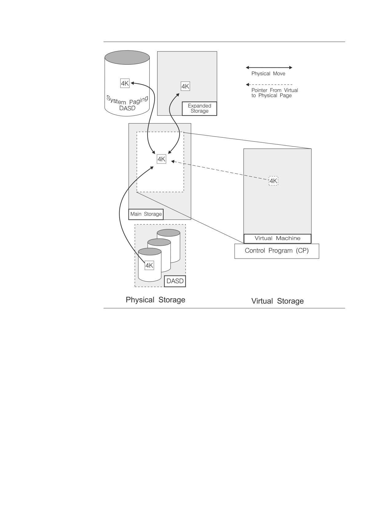
Figure 10. Standard Virtual Machine Storage
The VSE operating system only uses system paging DASD: it does not support
expanded storage. When the operating system runs out of free pages in main
storage, it moves the least recently used page directly to system paging DASD.
When a partition needs a page that it has previously used, the operating system
moves it back to main storage from system paging DASD, if it is not already in
main storage.
44
Performance Tuning Handbook
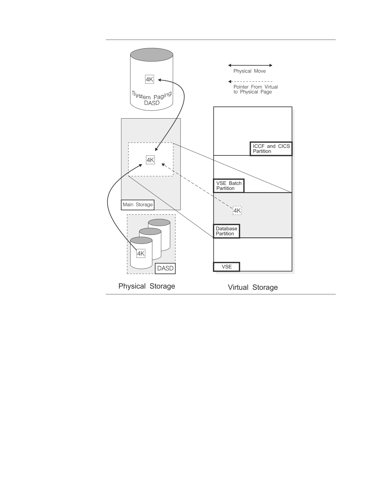
Figure 11. Standard VSE Partition Storage
This paging system accomplishes two things. First, it allows each virtual machine
or partition to use much more storage than could be accommodated in main
storage alone. Second, it keeps the most recently used pages in the storage devices
that are the fastest to access. (The most recently used pages are the ones most
likely to be used again in the near future.) Main and expanded storage are much
faster than system paging DASD, and while expanded storage can be as fast as
main storage, it is effectively slower because the operating system still needs to
move the page into main storage before it can use it.
The Hidden Cost of System Paging DASD: Each time the database machine or
partition (or the CICS partition) requires a page that the operating system cannot
find in main storage, a page fault occurs. The entire database machine or partition,
and therefore the entire database manager, must wait until the page is returned
from auxiliary storage. Consider a system that requires an average of 50ms to
return one page. So at 6 faults per second the database manager is idle 300 out of
1000ms, or almost one third of the time.
Note: This is not true for DASD I/O. A database machine does not wait for
*BLOCKIO, nor does a database partition wait for VSAM. The database
Chapter 3. Managing Storage and Configuring the Operating System
45
manager will dispatch another agent (unless you are running in single user
mode) while it waits for the DASD I/O to complete. Refer to “Database
I/O” on page 85.
This is also not true for Page Faults that occur in Data Space (when VMDSS
is enabled). Only one agent must wait for this kind of Page Faults.
Partition Deactivation (VSE): The TPBAL command (VSE system control
statement) specifies the number of partitions that are eligible for deactivation.
Whenever the TPIN macro (refer to the IBM VSE/ESA System Macros Reference
manual) is executed, the number of partitions specified by the TPBAL command
will be deactivated starting with the lowest priority partition and proceeding to the
highest eligible partition (excluding the partition which executed the TPIN macro).
All deactivated partitions are suspended (kept idle) until the TPOUT macro is
executed. This can become a severe problem if, for example, the deactivated
partition is an application server or a requester that is currently holding database
locks. Whenever possible, ensure that the database partition, the CICS partition, or
any DB2 Server for VSE batch partitions are NOT eligible for deactivation.
Storage Queues
A storage queue is a control structure that the database manager uses to share its
virtual space between processes. Queues are created at startup for:
v Each real agent
v The operator
v For checkpoint processing
v Recovery
v Global storage blocks such as accounting records.
The database manager allocates virtual storage to the different processes as they
require it (within limits). Once the storage has been allocated, it cannot be used by
any other process until the owning process releases it.
Real agent queues release all but 8KB of their allocated storage at the end of a
logical unit of work (LUW). Even if the real agent no longer requires the virtual
storage, it may keep it until the end of its current LUW.
Virtual space may be allocated either above or below the 16MB virtual storage line
(refer to “Storage Above 16MB (31 Bit Addressing)” on page 47.) However, because
certain control blocks and program structures must always reside below the 16MB
line, two storage queues are created for each process. One storage queue is for
blocks and structures that must always reside below the line, the other queue is for
blocks and structures that may reside either below or above the line.
When an agent requests virtual storage, the database manager decides whether the
blocks and structures must reside below the 16MB line or whether they can reside
either above or below the line. If they must reside below the line, space is allocated
in the below or B queue. If they may reside above or below the line, space is
allocated in the anywhere or A queue.
When the database manager looks for address space for blocks and structures in
the B queue, it looks below the 16MB line. When the database manager looks for
address space for blocks and structures in the A queue, it first tries to find free
space above the 16MB line. If there is none, it will try to find free space below the
line. If there is no free space below the line for either the A queue or for the B
46
Performance Tuning Handbook
queue, releasing unused packages from storage. If it can no longer release
packages, you will receive an error message and the database machine or partition
may abend.
Address Space Size
While increasing the size of your virtual database machine or partition may
increase your application server’s capacity, it does not necessarily improve its
performance. This is because the operating system has to supply enough fast real
storage to make the virtual storage appear to be real storage.
However, if sufficient real storage is available, you can take advantage of
additional virtual storage, by increasing:
v The number of concurrent users (NCUSERS). Refer to “Agents” on page 88.
v In VM, the number of pseudo agents (MAXCONN). Refer to “VM
(MAXCONN)” on page 92.
v In VSE, increase the number of connections between the CICS partition and the
database partition (CIRB transaction). Refer to “Tuning Parameters” on page 90.
You can also increase the number of remote DRDA users (RMTUSERS). Refer to
“VSE (RMTUSERS)” on page 92.
v The size of the buffers pools (NPAGBUF, NDIRBUF). Refer to “Database I/O”
on page 85.
v The number of lock request blocks (NLRBU, NLRBS). Refer to “Lock Escalation”
on page 99.
v The size of the package cache (NPACKAGE). Refer to “Package Cache” on page
88.
You need to monitor the real storage and the I/O in your system. If you do not
have enough main (and in VM expanded) storage to support additional virtual
storage, you may dramatically increase the load on your I/O subsystem and on
your processor. In extreme cases this can lead to thrashing. (The processor and I/O
subsystem spend most of their resources moving pages from main to auxiliary
storage and have little or no resources left for practical work.)
Storage Above 16MB (31 Bit Addressing)
In VM, your database machine’s address space can be larger than the old 16MB
limit. In VSE, you can use a database partition larger than the old 16MB limit.
(As mentioned in “Address Space Size,” anytime you increase your virtual storage,
you can realize significant performance improvements by using storage above
16MB, but only if you have the resources to support it.)
Saved Segments (VM Only)
A saved segment is a range of pages of virtual storage you can define to hold data
or reentrant code (programs), which can be shared by multiple virtual machines.
For detailed information, on how to create saved segments and which DB2 Server
for VM components can be loaded into them, refer to the DB2 Server for VM System
Administration manual.
Loading frequently used DB2 Server for VM components in saved segments has
several advantages:
v Because several users can access the same physical storage, real storage use is
minimized.
v Using saved segments decreases the I/O rate and DASD paging space
requirements, thereby improving virtual machine performance.
Chapter 3. Managing Storage and Configuring the Operating System
47
v Saved segments attached to a virtual machine can reside above its defined
virtual storage. This allows the virtual machine to use its defined storage for
other purposes.
For more information on saved segments, refer to the DB2 Server for VM System
Administration manual.
Virtual Disk Support for VSE/ESA for Internal Dbspaces
Your internal dbspaces can use a virtual disk to improve their performance. Virtual
Disk Support lets you use a data space as a virtual disk. A virtual disk is much
faster than a conventional disk because it uses main storage instead of DASD. The
virtual disk appears to any program or job as just another disk, only faster.
However, virtual disk storage is temporary. Anything in a virtual disk is lost
whenever the VSE operating system is restarted. For this reason, DO NOT use
virtual disks for anything other than internal dbspaces. These dbspaces are only
used as temporary workspace, so it does not matter if their contents are lost. The
storage pool containing the virtual disk must NOT be used for any permanent
dbspaces.
While the use of virtual disks is limited to internal dbspaces, they can improve the
performance of index creation, joins, sorts, and other operations that require
temporary workspace.
Remember, as mentioned in “Address Space Size” on page 47, anytime you
increase your use of virtual storage, you can realize significant performance
improvements, but only if you have the real storage to support it.
Note: It is recommended that database generation be done with real minidisks
only. If you decide to generate a database which uses a virtual disk, ensure
that the virtual disk is used in a pool containing only internal dbspaces.
Using Virtual Disks with Internal Dbspaces: To use a virtual disk with internal
dbspaces, you must:
1. Take an archive of your database, before making any changes to it.
2. Modify the IPL procedure and the background initialization procedure to create
a virtual disk.
3. Define a VSAM user catalog and dbextent on the virtual disk.
4. Add a label for the dbextent in the cataloged procedure and add the dbextent
to a NEW storage pool that will contain only internal dbspaces.
5. Move some of the dbextents from the original pool that contained the internal
dbspaces into the new pool or define additional physical dbextents to be added
to the new pool.
6. Add internal dbspaces to the new storage pool.
7. Backup the VSAM user catalog defined on the virtual disk so that it can be
restored whenever the VSE system is restarted.
8. Modify the application server startup job to restore the VSAM user catalog if
the VSE system has been restarted since the VSAM user catalog and dbextent
were created.
9. Archive your database after making the above changes so that you have an
archive that reflects these changes.
48
Performance Tuning Handbook
A detailed example of how to complete these steps appears below. For more
information on virtual disks in VSE/ESA, refer to the IBM VSE/ESA Planning
manual and the IBM VSE/ESA Extended Addressability manual.
Note: All of the following steps should be read before executing any of them.
Step 1, Archive Your Database: This will be needed if problems arise during the
setup for using a virtual disk and you need to restore your database to its previous
state without any virtual disk.
Step 2, Modify IPL Procedure: Modify the IPL procedure to do the following:
v Include ADD statements for the virtual disk addresses
v Increase VSIZE and page data set allocation to accommodate the new virtual
disk.
For example, consider a system where a 20MB virtual disk is added to a VSE
system with VSIZE=75MB:
009,$$A$SUPX,VSIZE=95M,VIO=576K,VPOOL=194K,LOG
ADD 900:906,FBAV
DPD VOLID=DOSRES,CYL=209,NCYL=100,TYPE=N,DSF=N
DPD VOLID=DOSRES,CYL=398,NCYL=8,TYPE=N,DSF=N
DPD VOLID=DOSRES,CYL=410,NCYL=29,TYPE=N,DSF=N
DLA NAME=AREA1,VOLID=DOSRES,CYL=60,NCYL=3,DSF=N
SVA PSIZE=640K,SDL=300,GETVIS=768K
/+
/*
This example increases the VSIZE of the VSE operating system from 75MB to
95MB. It reserves virtual addresses 900 through 906 for fixed block architecture
virtual disks, and it sets aside an additional 29 cylinders of 3390 DASD on
DOSRES volume starting at address 410 for system paging DASD. (108 cylinders
were already being used at addresses 209, and 398. Also, there are 180 4KB pages
in every 3390 cylinders. So 29 cylinders is equal to 20MB.)
Step 3, Define and Initialize a Virtual Disk: Create a procedure (to be invoked
as part of the background initialization JCL, for example $0JCL) that will do the
following:
v Define data space size using SYSDEF command
v Initialize virtual disks using // VDISK command.
For example:
Chapter 3. Managing Storage and Configuring the Operating System
49

* DEFINE THE SIZE OF THE DATASPACE
// SYSDEF DSPACE,DSIZE=20M
* DEFINE AND INITIALIZE EACH VIRTUAL DISK
// VDISK UNIT=900,BLKS=40320,VOLID=QPVDS1,VTOC=008
/*
/+
This example reserves approximately 20MB of virtual storage for virtual disks.
(Remember you do not need 20MB of real storage to support 20MB of virtual
storage.) The virtual disk at address 900 uses approximately 20MB of that storage
(40320 512-byte blocks, with 8 512-byte blocks of that reserved for the VTOC). (The
virtual disk addresses were defined in Step 2.)
Note: Because of the structure of a virtual disk, blocks must be allocated in
multiples of 960 blocks. So instead of 2048 512-byte blocks for 1MB of
storage, you can only allocate 1920 blocks.
Step 4, Define a Backup File: Define a sequential file on a real disk for use later
when backing up the VSAM user catalog (defined on the next step on a virtual
disk). For example:
* DEFINE A SEQUENTIAL FILE FOR VDISK UCAT BACKUP
// EXEC IDCAMS,SIZE=AUTO
DEFINE NONVSAM (NAME(VDISK1.UCAT.BKUP) -
DEVICETYPES(3390) VOLUMES(SYSWK1))
/*
This example creates a backup file called VDISK1.UCAT.BKUP.
Note: The above JCL does not work if it is used on FBA DASD. If only FBA DASD
is used, do one of the following:
v Skip this step
v Use a VSAM ESDS file for the backup file.
Step 5, Define a VSAM User Catalog: Define a VSAM user catalog on the virtual
disk using the DEDICATE option. For example:
* DEFINE A VSAM USER CATALOG
// EXEC IDCAMS,SIZE=AUTO
DEFINE USERCATALOG ( -
NAME (VDS1.USER.CATALOG
) -
DEDICATE -
VOLUME (QPVDS1))
/*
This example creates a VSAM user catalog called VDS1.USER.CATALOG on volume
QPVDS1 and dedicates the entire volume for this VSAM user catalog. (Volume
QPVDS1 was defined in Step 3.)
50
Performance Tuning Handbook
Step 6, Define a Virtual Disk Dbextent: Define a dbextent (VSAM cluster) on the
virtual disk. For example:
* ADD CLUSTERS FOR THE DATA BASE VIRTUAL DISK
// DLBL VDSUC1,’VDS1.USER.CATALOG’,,VSAM
* DEFINE CLUSTERS
// EXEC IDCAMS,SIZE=AUTO
DEFINE CLUSTER (NAME(SQL34.DDSK8.VDSK.DB) NONINDEXED REUSE -
CNVSZ (4096) BLOCKS(39360) VOL(QPVDS1) -
RECSZ (4089 4089) SHR(2)) CAT(VDS1.USER.CATALOG)
/*
This example defines a dbextent named SQL34.DDSK8.VDSK.DB in the VSAM user
catalog VDS1.USER.CATALOG (The VSAM user catalog was defined in Step 5.)
Step 7, Add a Label for the Virtual Disk Dbextent: Update the cataloged
procedure to include a DLBL statement for the new dbextent. For example:
* CATALOG DATABASE DBEXTENT LABELS
// EXEC LIBR,PARM=’MSHP’
ACCESS S=IJSYSRS.SYSLIB
CATALOG DTLDVDSK.PROC R=Y
***************** SQL/DS DBEXTENT LABELS
**************
// DLBL TSQLUC,’TSQL.USER.CATALOG’,,VSAM
// DLBL VDSUC1,’VDS1.USER.CATALOG’,,VSAM
// DLBL BDISK,’SQL34.BDISK.DTLD.DB’,,VSAM,CAT=TSQLUC
// DLBL LOGDSK1,’SQL34.LOGDSK1.DTLD.DB’,,VSAM,CAT=TSQLUC
// DLBL DDSK1,’SQL34.DDSK1.DTLD.DB’,,VSAM,CAT=TSQLUC
// DLBL DDSK7,’SQL34.DDSK7.DTLD.DB’,,VSAM,CAT=TSQLUC
// DLBL DDSK8,’SQL34.DDSK8.VDSK.DB’,,VSAM,CAT=VDSUC1
/+
/*
This example adds a DLBL statement for DDSK8 that identifies dbextent
SQL34.DDSK8.VDSK.DB. (The dbextent was created in Step 6.) DDSK7 is one of the
dbextents that belonged to the original internal dbspace storage pool.
Step 8, Add Dbextents to a New Storage Pool: Add dbextents to the new storage
pool by following instructions included in the DB2 Server for VSE System
Administration manual. (Refer to “adding and deleting dbextents”.)
To avoid using too much real storage, it is recommended that you include at least
two dbextents in the new pool. The first must be the virtual disk. The second,
should be a physical dbextent that can accommodate the overflow from the virtual
disk. You can use some of the dbextents from the original pool that contained the
internal dbspaces (in this example DDSK7). Make the total size of both dbextents
large enough to accommodate your current internal dbspaces and make the virtual
disk as large as possible without over committing real storage.
Also, ensure that you add the virtual dbextent before you add any physical
dbextents. The database manager searches the dbextents for a free page in the
order that they were added.
Chapter 3. Managing Storage and Configuring the Operating System
51
Attention: Do not accidentally place the virtual disk in an existing storage pool
that contains anything other than internal dbspaces. You will lose valuable data
and a full database or pool level restore will be required.
The following is an example of the ARISADD member, which specifies how
procedure ARIS250D will add and delete dbextents to and from pools:
POOL 9
ADD 8 9
DELETE 7
ADD 7 9
ARCHIVE
This example adds dbextent 8 (DDSK8) to storage pool 9. (DDSK8 was identified
in Step 7.) Ensure that you add the virtual disk dbextent to a new storage pool
(reserved only for internal dbspaces). It also removes dbextent 7 (DDSK7) from the
original pool that contained the internal dbspaces. It then adds it to the new pool
(pool 9) that contains the virtual disk dbextent.
Step 9, Back Up the Virtual Disk VSAM User Catalog: Back up the VSAM user
catalog defined on the virtual disk into the sequential file on a real disk. For
example:
// LIBDEF PHASE,SEARCH=IJSYSRS.SYSLIB
* THIS JOB UNLOADS A VSE/VSAM CATALOG USING THE REPRO COMMAND
// DLBL IJSYSCT,’VSAM.MASTER.CATALOG’,,VSAM
// ASSGN SYS001,DISK,VOL=SYSWK1,SHR
// DLBL CATOUT,’VDISK1.UCAT.BKUP’,999
// EXTENT SYS001,SYSWK1,1,0,33315,75
// DLBL IJSYSUC,’VDS1.USER.CATALOG’,
X
,VSAM
// EXEC IDCAMS,SIZE=AUTO
REPRO INFILE (IJSYSUC) -
OUTFILE (CATOUT -
ENVIRONMENT ( -
BLOCKSIZE (2068) -
RECORDFORMAT (VARBLK) -
RECORDSIZE (516) -
) -
)
/*
This example unloads the VSAM user catalog VDS1.USER.CATALOG to the backup file
VDISK1.UCAT.BKUP. (The backup file was created in Step 4.) The backup file will be
used to restore the VSAM user catalog on the virtual disk whenever the VSE
system is restarted. Restoring the VSAM user catalog redefines the VSAM space
and cluster previously defined on the virtual disk and sets the high used RBA to
what is was before the system restart, thus allowing the database manager to
successfully use it.
Step 10, Add Internal Dbspaces to the New Pool: Invoke the application server
to add only internal dbspaces into this new pool. For example:
52
Performance Tuning Handbook
* ADD INTERNAL DBSPACES TO THE DATABASE
// LIBDEF *,SEARCH=PRD2.SQL340
// EXEC PROC=DTLDVDSK
// EXEC ARISQLDS,SIZE=AUTO,PARM=’SYSMODE=S,STARTUP=S’
INTERNAL 50 1024 9
/*
This example JCL creates 50 internal dbspaces, each of 1024 4KB pages, in storage
pool 9. (Storage pool 9 was created in Step 8.)
Step 11, Add Conditional JCL to Application Server Startup: Create conditional
JCL that does the following:
v Check that the dbextent defined earlier on the virtual disk still exists (1
and
2). If
it does not, do the following:
- Disconnect the VSAM user catalog from the master catalog (3)
- Redefine the VSAM user catalog on the virtual disk (4)
- Restore the VSAM user catalog from the sequential file (5)
- If the restore fails for any reason cancel the job (6).
v Start the application server.
For example:
// DLBL IJSYSCT,’VSAM.MASTER.CATALOG’,,VSAM
// ASSGN SYS001,DISK,VOL=SYSWK1,SHR
// DLBL VDSBKUP,’VDISK1.UCAT.BKUP’
// EXTENT SYS001,SYSWK1,1,0
// DLBL IJSYSUC,’VDS1.USER.CATALOG’,,VSAM
// EXEC IDCAMS,SIZE=AUTO
LISTCAT CAT(VDS1.USER.CATALOG) ENT(SQL34.DDSK8.VDSK.DB)
ALL
(1)
IF LASTCC NE 0 THEN DO
(2)
EXPORT VDS1.USER.CATALOG DISCONNECT
(3)
DEFINE USERCATALOG ( NAME(VDS1.USER.CATALOG) -
(4)
DEDICATE VOLUME (QPVDS1))
IF LASTCC NE 0 THEN CANCEL JOB
REPRO INFILE (VDSBKUP ENVIRONMENT -
(5)
(BLOCKSIZE (2068) -
RECORDFORMAT (VARBLK) -
RECORDSIZE (516))) -
OUTFILE (IJSYSUC)
IF LASTCC GT 4 THEN CANCEL JOB
(6)
END
/*
Place this sample JCL in front of your current application server startup job. It
checks for the existence of dbextent SQL34.DDSK8.VDSK.DB in the VSAM user
catalog VDS1.USER.CATALOG. If it no longer exists, the JCL restores the VSAM user
catalog from the backup created in Step 4. The application server will then start
normally and will use the virtual disk for internal dbspaces.
Step 12, Archive Your Database: The ADD DBEXTENT and DELETE DBEXTENT
operations are not recorded in the log. Since these operations update the directory
(but not the database itself), problems can be encountered if you normally archive
Chapter 3. Managing Storage and Configuring the Operating System
53
the database and then try to restore that archive with the ADD DBEXTENT or
DELETE DBEXTENT occurring in between the archive and the restore. Archiving
before and after you make changes to the virtual disk will assist you if problems
occur. For more information, refer to the DB2 Server for VSE System Administration
manual.
Virtual Disk Support for VM/ESA for Internal Dbspaces
Your internal dbspaces can use a virtual disk to improve their performance. Virtual
Disk Support lets you use a data space as a virtual disk. A virtual disk is much
faster than a conventional disk because it uses main storage instead of DASD. The
virtual disk appears to any program or job as just another disk, only faster.
However, virtual disk storage is temporary. All data on a virtual disk is lost when
it is detached from a user ID or when the user ID logs off. For this reason, DO
NOT use virtual disk for anything other than internal dbspaces. These dbspaces
are only used as temporary workspace, so it does not matter if their contents is
lost. The storage pool containing the virtual disk must NOT be used for any
permanent dbspaces.
While the use of a virtual disk is restricted to internal dbspaces, they can be used
to improve the performance of index creations, joins, sorts, and other operations
that require temporary workspace.
Remember, anytime you increase your use of virtual storage, you can realize
significant performance improvements, but only if you have the real storage to
support it.
Note: It is recommended that database generation be done with real minidisks
only. If you decide to generate a database which uses a virtual disk, ensure
that the virtual disk is used in a pool containing only internal dbspaces.
Using Virtual Disks with Internal Dbspaces: To use a virtual disk with internal
dbspaces, you must:
1. Take an archive of your database, before making any changes to it.
2. Define a virtual disk in the database manager’s VM Directory entry.
3. Run the SQLADBEX EXEC to add the virtual disk as the first dbextent of a
NEW storage pool. The virtual disk must be the first dbextent in the new pool.
If you have dbextents in the old storage pool where your internal dbspaces are
currently defined, you should delete some of these dbextents from the old pool
and add them to the new pool. Alternatively, you could add one or more real
disk dbextents to the new pool.
4. Run the SQLADBSP EXEC to move your internal dbspaces to the new pool.
5. Modify the 'CP LINK' command for the virtual disk in the 'dbname SQLFDEF
Q' file.
6. Modify the database manager’s PROFILE EXEC or database start up EXEC to
CMS FORMAT and RESERVE the virtual disk and make a duplicate LINK to
this virtual disk. (this is explained further in the following detailed steps)
7. Archive your database after making the above changes, so that you have an
archive that reflects these changes.
A detailed example of how to complete these steps appears below. Please read all
the steps before executing any of them.
54
Performance Tuning Handbook
Step 1, Archive Your Database: This will be needed if problems arise during the
setup for using a virtual disk and you need to restore your database to its previous
state without any virtual disk.
Step 2, Define a Virtual Disk in the Database Manager’s VM Directory Entry:
Determine the size of the virtual disk to be added. It should be large enough for
most sorts, but must not be so large as to cause excessive VM paging. Define this
virtual disk in the VM Directory, similar to:
MDISK 0329 FB-512 V-DISK nnnnnnnn M
For information about defining a virtual disk in a VM Directory, refer to the
VM/ESA: Planning and Administration manual.
Step 3, Add Dbextents to a New Storage Pool: Add the virtual disk, and
possibly other dbextents, to a new storage pool. For information about using the
SQLADBEX EXEC, refer to the DB2 Server for VM System Administration manual.
To avoid using too much real storage, it is recommended that you include at least
two dbextents in the new pool. The virtual disk must be the first dbextent in the
new pool. Other dbextents should be real minidisks to accommodate the overflow
from the virtual disk. You can use some of the dbextents from the pool that
originally contained the internal dbspaces. Make the total size of the dbextents in
the new pool large enough to accommodate your current internal dbspaces.
Also, ensure that you add the virtual dbextent before you add any real minidisks.
The database manager searches the dbextents for a free page in the order they
were added.
If you are also using DB2 Server DSS, you should use SEPINTDB=Y to use your
internal dbspaces in a data space, instead of using a virtual disk. If you still want
to use a virtual disk, you MUST update your Storage Pool Specification file to
specify 'BLK' and 'SEQ' for the storage pool containing the virtual disk. VM does
not allow a virtual disk to be mapped to a data space. In this case, message
ARI2018E will be issued identifying the virtual disk address.
Attention: Do not accidentally place the virtual disk in an existing storage pool
containing permanent dbspaces. You will lose valuable data and a full database or
pool level restore will be required.
When you run the SQLADBEX EXEC, you specify the actions to be taken by
answering the prompts. When you see message ARI6145D, reply 1 (yes), to view
the 'dbname SQLADBEX A' file created from the prompts.
Assume you have the following set up and are changing to use a virtual disk for
internal dbspaces:
v Your internal dbspaces are currently defined in pool 3, which also contains
permanent dbspaces.
v Pool 3 currently has 3 dbextents, addresses 324, 325, and 326, which correspond
to dbextent numbers 4, 5, and 6.
v You have a virtual disk defined at address 329 and you want to add it to the
new pool number 8, as dbextent number 9.
v You want to 'move' dbextents 5 and 6 in pool 3 to the new pool 8.
v You DO want to take an archive after these changes.
Note: Running the SQLADBEX EXEC will cause a break in the continuity of
your log archives, so a database archive should always be taken.
Chapter 3. Managing Storage and Configuring the Operating System
55
After starting the SQLADBEX EXEC and entering the information at the prompts,
reply 1 (yes) to message ARI6145D. This will display the 'dbname SQLADBEX A'
file in XEDIT; its contents can be reviewed, modified, or both. This file specifies the
sequence of actions that SQLADBEX will perform. Given our assumptions above,
the file will appear as follows:
ADD 9 8
<-- add virtual disk to pool 8
DELETE 5 3
<-- delete dbextent 5 from pool 3
DELETE 6 3
<-- delete dbextent 6 from pool 3
ADD 5 8
<-- add dbextent 5 to pool 8
ADD 6 8
<-- add dbextent 6 to pool 8
ARCHIVE
<-- an archive will be taken
Refer to the DB2 Server for VM System Administration manual for more details,
cautions and warnings concerning the adding and deleting of dbextents.
The last step of the SQLADBEX EXEC will update the 'dbname SQLFDEF Q' file,
to match dbextents that have been added, deleted, or both. The 'CP LINK'
command for the virtual disk in this file must be updated; this is documented in a
following step.
Step 4, Move the Internal Dbspaces to the New Storage Pool: This step will
'move' the internal dbspaces from the old pool to the newly added pool which
contains the virtual disk, by using the SQLADBSP EXEC. You may also add
permanent dbspaces to the database at this time (except into the new pool) or you
can simply redefine the pool where internal dbspaces will be placed. Remember,
this new pool, with the virtual disk dbextent, can ONLY contain internal dbspaces.
For information about using the SQLADBSP EXEC, refer to the DB2 Server for VM
System Administration manual.
Step 5, Modify the 'dbname SQLFDEF Q' File: In this step, you will edit and
modify the 'dbname SQLFDEF Q' file to change the 'CP LINK' mode for the virtual
disk dbextent. This is required to allow the virtual disk to only be formatted and
reserved once per IPL CMS of the database manager. If this step is not performed,
the virtual disk must be formatted and reserved prior to each start up of the
database manager (for example, SQLSTART).
This is done by having the virtual disk linked to the database manager virtual
machine twice. When the 'dbname SQLFDEF Q' file detaches the virtual disk, the
second link remains attached to the machine and the formatting of the virtual disk
is not lost. This second link and the formatting is done from the database
manager’s PROFILE EXEC (this is set up in the next step).
Be sure you have the production minidisk (normally 'Q') accessed R/W. XEDIT the
'dbname SQLFDEF Q' file. Locate the line containing the 'CP LINK userid cuu cuu
W' statement for the address ('cuu') of the virtual disk. Change the CP LINK
'MODE' character from 'W' to 'M'.
Attention: If you delete the virtual disk extent and add it again (through the
SQLADBEX EXEC), you must again change the LINK Mode character from 'W' to
'M'.
Step 6, Modify the PROFILE EXEC: In this step you will modify the database
manager’s PROFILE EXEC so that the virtual disk will be CMS formatted and
reserved each time the database manager virtual machine IPL’s CMS. In addition,
a second link to the virtual disk will be set up (see the previous step).
56
Performance Tuning Handbook
Attention: If an error occurs such that the virtual disk is not usable, the database
cannot be brought up. In this situation, you must correct the error to make the
virtual disk usable, or you must replace the virtual disk with a real minidisk at the
same address (and at least the same size). The replacement minidisk must be
formatted and reserved, as usual, before the database is brought up.
It is recommended that a separate EXEC be created to perform the LINK, FORMAT
and RESERVE commands, and that this EXEC be called from the PROFILE EXEC.
You can place the following statements in your PROFILE EXEC to initialize the
virtual disk for usage:
’EXEC PREPVDSK’
/* Call EXEC to Prepare Virtual Disk */
If rc ¬= 0 Then Do; Say "PREPVDSK rc =" rc; Exit rc; End
Note: The 'If' statement above will cause the PROFILE EXEC to end if an error is
returned from the PREPVDSK EXEC. This assumes that the PROFILE EXEC
will eventually invoke the SQLSTART EXEC after the virtual disk has been
initialized. This is done because the database cannot be started if the virtual
disk is not properly initialized. You may need to tailor this processing to suit
your particular operational environment.
The following is a sample 'PREPVDSK EXEC':
/* REXX */ Trace ’O ’; Address ’COMMAND’
/* Use this EXEC to FORMAT and RESERVE a Virtual Disk,
*/
/* that is used as the FIRST Dbextent of a Storage Pool containing
*/
/* ONLY INTERNAL DBSPACES.
*/
/*
*/
/* ATTENTION: This process, to use a Virtual Disk, requires that the */
/*
CP Link Mode letter be changed from ’W’ to ’M’ in the
*/
/*
SQLFDEF file for the CP LINK command for the DATABASE
*/
/*
Address of the Virtual Disk.
*/
/*
*/
/* This EXEC should be called from the PROFILE EXEC of the Database
*/
/* Virtual Machine, to prepare the Virtual Disk for use.
*/
/*
(once per LOGON/IPL of the Database Machine)
*/
/*
*/
/* The Virtual Disk MDISK is Linked R/O with an unused address,
*/
/* (which is refered to below as the PERANENT ADDRESS) so that
*/
/* that subsequent Detaches of the normal address (refered to below
*/
/* as the SQLFDEF ADDRESS) by this EXEC and the SQLFDEF file will
*/
/* NOT lose the FORMAT/RESERVE information.
*/
/*
*/
/* The Virtual Disk MDISK is Linked again, R/W, with its SQLFDEF
*/
/* address, for the FORMAT/RESERVE processing. This address is then
*/
/* Detached. It will be Linked again later by the SQLFDEF file when */
/* the database machine runs the SQLSTART EXEC.
*/
/*
*/
/* If the R/O Link of the Virtual Disk is detached by mistake,
*/
/* you MUST run this EXEC before running SQLSTART again.
*/
/*
*/
/********* UPDATE THE FOLLOWING 5 VARIABLES AS APPROPRIATE:
*********/
dbname = ’dbname
’
/* Database Name
*/
pdisk
= ’0cuu’
/* Virtual Disk PERMANENT Address
*/
vdisk
= ’0cuu’
/* Virtual Disk SQLFDEF Address
*/
vlabel = ’DDKnn
’
/* Virt Disk Label (Dbextent Number)*/
ufm
= ’Z’
/* Unused Filemode Letter
*/
z=Diagrc(8?,’CP DETACH’ vdisk)
/* Be sure SQLFDEF Addr is NOT Linked */
z=Diagrc(8?,’CP LINK *’ vdisk pdisk ’RR’)
/* Get PERMANENT R/O Link */
Parse Var z cprc . ; If cprc ¬= 0 Then Exit cprc
z=Diagrc(8?,’CP LINK *’ vdisk vdisk ’M’)
/* Get SQLFDEF R/W Link */
Parse Var z cprc . ; If cprc ¬= 0 Then Exit cprc
’SET CMSTYPE HT’; ’RELEASE’ ufm; ’SET CMSTYPE RT’
Push vlabel
Chapter 3. Managing Storage and Configuring the Operating System
57
Push ’1’
’FORMAT’ vdisk ufm ’(BLKSIZE 4096 NOERASE’
/* FORMAT the Vdisk */
If rc ¬= 0 Then Exit rc
Push ’1’
’RESERVE’ dbname vlabel ufm
/* RESERVE the Vdisk */
If rc ¬= 0 Then Exit rc
’SET CMSTYPE HT’; ’RELEASE’ ufm; ’SET CMSTYPE RT’
z=Diagrc(8?,’CP DETACH’ vdisk)
/* Detach the SQLFDEF address again, */
Exit 0
/* ... it will be re-Linked by SQLFDEF during SQLSTART. */
Step 7, Archive Your Database: Neither the ADD DBEXTENT nor the DELETE
DBEXTENT operation is recorded in the log. Since these operations update the
directory (but not the database itself), problems can be encountered if you
normally archive the database and then try to restore that archive with the ADD
DBEXTENT or DELETE DBEXTENT occurring in between the archive and the
restore. For more information about this problem, refer to the DB2 Server for VM
System Administration manual. Archiving before and after you make changes to the
virtual disk will assist you if problems occur.
DASD Storage
How you manage DASD storage affects performance in four ways:
How Storage Is Divided
How you divide a limited amount of storage between indexes and data,
and among dbspaces and among storage pools determines to a large
degree how each will perform in different situations.
Wasted Storage
Wasted storage in itself may not affect the performance of the system that
is using it, but it may represent a resource that could be used to improve
performance elsewhere.
Distributing DASD I/O
How well you balance the demand for DASD I/O across several DASD
devices, controllers and channels can affect how fast the database manager
can retrieve information from DASD.
Running out of Storage
While running out of storage can disrupt your users because you are
forced to bring down the application server to add storage, just getting
close can degrade performance. (If you reach the application server’s short
on storage level you trigger unnecessary SOSLEVEL checkpoints, refer to
“Short on Storage Cushion” on page 59.)
In VSE
The directory, logs, and dbextents are VSAM Entry Sequenced Data Sets (ESDS)
with a control interval size of 512 bytes for the directory and 4096 bytes for the
logs and dbextents. The database manager uses VSAM Control Interval processing
to read and write records to the VSAM ESDS.
In VM
The directory, logs, and dbextents are CMS reserved minidisks with a blocksize of
512 bytes for the directory and 4096 bytes for the logs and dbextents (the directory
may have a blocksize of 4096 bytes, if Data Spaces Support is used). These
minidisks have CMS-like files that are in a format to be used with the IUCV
*BLOCKIO I/O system that reads and writes records to these files. These minidisks
are called reserved because they have been processed by the CMS RESERVE
58
Performance Tuning Handbook
command. It specifies that the minidisk consists of a single CMS file, which is
allocated using all available disk blocks. This CMS file cannot be processed by
most CMS file system commands and must never be modified, except by the
database manager.
Mapping of Dbspaces to DASD
Logical dbspaces must be mapped to physical dbextents on DASD. The database
manager does this by maintaining page map table(s), for each dbspace, which map
a given dbspace page to its location on DASD. The page map table is stored in the
DB2 Server for VSE & VM directory. There can be multiple page map tables per
dbspace. Each page map table block is equivalent to 128 pages in a dbspace.
Logical To Physical Page Relationships
Physical page slots in the storage pool are allocated to the dbspaces dynamically
upon first reference. Once a logical page has had a physical page slot allocated to
it, it will continue to have a physical page allocated, even if empty, until the
dbspace is dropped or empty pages are released. Empty pages can be released
back to the storage pool either by running the SQLRELEP EXEC in VM or by
bringing up the server using STARTUP=P in VSE. For more information, refer to
“Running out of Dbspace Pages” on page 65
Storage Pools
A storage pool is a collection of one or more dbextents, which can be used to
control the distribution of the database across DASDs. The maximum number of
storage pools for a given database is specified by the database generation keyword
MAXPOOLS. A storage pool does not exist until a dbextent is assigned to it.
Dbspaces are assigned to a given storage pool when they are defined. That means
when physical page slots are allocated to the dbspace, they are allocated from the
storage pool to which the dbspace belongs.
In addition, if the storage pool contains more than one dbextent, the database
manager allocates pages in a storage pool in sequence, usually allocating all the
pages in one dbextent before using the next dbextent. With the DB2 Server DSS
Feature, the database manager can distribute pages evenly across all the extents,
refer to “Striping” on page 198.
Managing Storage Pool Space
Short on Storage Cushion
The short on storage (SOS) cushion helps you avoid completely filling a storage
pool. If the database manager is running:
v In SUM with LOGMODE not equal to N or
v In MUM
and the percentage of space available in one pool falls below the SOS level, the
database manager performs a checkpoint to release shadow pages (refer to
“Shadow Pages” on page 63). If this does not release enough pages to fall below
the SOS level, a warning message is sent to the operator. If you are already short
on storage and need more storage in a pool, refer to “Running out of Dbspace
Pages” on page 65.
Tuning Parameter (SOSLEVEL): While it is acceptable to reach the SOSLEVEL
initialization parameter occasionally, do not let any of your storage pools hover
around it. SOSLEVEL initiated checkpoints are unnecessary overhead. If they occur
Chapter 3. Managing Storage and Configuring the Operating System
59
frequently, it is a good sign that you should either free space in the overloaded
pools, or increase their size by adding dbextents.
Do not just lower the SOSLEVEL to avoid checkpoints. If you have less than 10%
free space in a storage pool the database manager will initiate a checkpoint during
a rollback even if you set SOSLEVEL below 10%.
Instead, set SOSLEVEL to at least 15% and try to keep at least 25% free space in
each storage pool. This ensures that even if you accumulate a large number of
shadow pages in a pool, the database manager will not initiate unnecessary
checkpoints.
Performance Indicator (SHOW POOL): Use the SHOW POOL operator command
to determine what percentage of each storage pool is full. If the free space in a
pool falls below the SOSLEVEL parameter, the SHORT ON STORAGE flag appears in
the report for that pool. (Refer to page 26.)
Also watch the CHKPOINT counter. If you notice an excessive number of
checkpoints occurring during insert or update transactions, the database manager
may be doing the following:
v Reaching the SOSLEVEL and performing a checkpoint.
v The checkpoint releases just enough shadow pages for the pool to fall below the
SOSLEVEL.
v Subsequent processing quickly refills the pool to the SOSLEVEL and another
checkpoint is taken.
The database manager may spend so much time processing SOSLEVEL
checkpoints that it can perform little useful work. Changing the SOSLEVEL will
not help this problem. Instead, add storage to the pool, refer to “Running out of
Dbspace Pages” on page 65.
Types of Pages
There are four types of pages that can reside in a dbspace:
Header Pages
These pages contain an inventory of all the dbspace attributes, tables and
indexes created in the dbspace.
Data Pages
These pages contain table rows that may be from several different tables in
the dbspace.
Index Pages
These pages contain index entries. Each page contains information for one
specific index on one specific table.
Shadow Pages
These pages are used to ensure that the database manager can reconstruct
changes to the database after a system failure, refer to “Shadow Pages” on
page 63.
Number of Header Pages
Because there are never many header pages in a single dbspace, never more than
eight, they do not represent a significant impact on performance. We suggest that
they remain at the system default of eight.
60
Performance Tuning Handbook