PowerWorld Simulator version 11. Manual - page 1
Table of Contents
Getting Started With PowerWorld
1
Chapter 1: Getting Started With PowerWorld
1
About this Manual
2
Introduction to PowerWorld Simulator
3
Introduction to Simulator Add-On Tools
4
What's New in Version 11.0
5
Help
8
PowerWorld Interface
9
Windows Basics
9
PowerWorld Simulator: Getting Started
10
Edit Mode Introduction
11
Run Mode Introduction
12
Script Mode Introduction
13
Message Log
14
Web Publishing
15
Memo Display
16
Status Bar
17
Toolbars
18
Using the Toolbars
18
Main Menu Toolbar
19
File Toolbar
20
Program Toolbar
21
Edit Toolbar
22
Insert Toolbar
23
Format Toolbar
24
Case Information Toolbar
25
Zoom Toolbar
27
Options/Info Toolbar
28
Run Mode Toolbar
29
Solution Options Toolbar
30
Animated Flows Options Toolbar
31
Pie Chart/Gauge Options Toolbar
32
Thumbnail View Options Toolbar
33
Contouring Options Toolbar
34
Oneline Options Toolbar
35
Toolbars Customization
36
Using Oneline Diagrams
39
Chapter 2: Using Oneline Diagrams
39
Oneline Diagram Overview
40
Relationship Between Display Objects and the Power System Model
41
Oneline Tools and Options
42
Oneline Local Menu
42
Oneline Display Options Dialog
44
Display Options
45
Pie Chart/Gauge Options
47
Pie Charts/Gauges: Lines
48
Pie Charts/Gauges: Interfaces
50
i
Table of Contents
Pie Charts/Gauges: General Options
52
Animated Flows Options
53
Thumbnail View
55
Substation Display Options
57
Set Custom Detail Dialog
59
Oneline Animation
61
Copying Onelines to Other Programs
62
GIS Tools
63
Great Circle Distance Dialog
63
Convert XY to LL Dialog
64
Geography/Coordinates
65
Shape File Import
66
GIS Shapefile Data: Control
67
GIS Shapefile Data: Modify Shapes or Projection
68
GIS Shapefile Data: Modify Colors and Format
69
GIS Shapefile Data: Shapefile Objects
70
Changing the Oneline View
71
Oneline Screen Coordinates
71
Oneline Zooming and Panning
72
Save View Level Dialog
73
Window Menu Command
75
Oneline Conditional Display of Objects
76
Keyboard Short Cut Actions Dialog
77
Printing Oneline Diagrams
79
Printing Oneline Diagrams
79
Print Options Dialog
80
Printer Setup
82
Creating, Loading, and Saving Simulator Cases
83
Chapter 3: Creating, Loading, and Saving Simulator Cases
83
File Menu
84
Case Formats
85
Validating a Case
86
Opening Files
86
Opening a Simulation Case
86
Opening a Oneline Diagram
87
Recently Opened Cases
88
Creating Files
88
Building a New Case
88
Building a New Oneline
89
Closing Files
90
Saving Cases
90
Saving a Oneline
91
Close Oneline
92
Additional File Formats
93
Area/Zone Load Schedule Format (*.shd)
93
Automatic Area Controls Format (*.aac)
94
Auxiliary File Format (*.aux)
95
Generator Capability Curves Format (*.gcp)
96
Generator Cost Data Format (*.gcd)
97
ii
Table of Contents
Generator Cost Curve Data Options
98
Identify Cross Compound Units
99
Injection Groups Format (*.inj)
100
Interface Data Format (*.inf)
101
Sequence Data Format
102
Exporting Onelines in Different Graphic Formats
104
Saving Images as Jpegs
105
Saving Admittance Matrix and Jacobian Information
106
Building a Oneline Diagram
107
Chapter 4: Building a Oneline Diagram
107
Overview
108
Edit Mode Overview
108
Edit Mode General Procedures
109
Insert Menu
110
Oneline Display Options
111
Anchored Objects
112
Inserting and Placing Multiple Display Fields
113
Areas, Zones and Owners
114
Area/Zone/Super Area Display Objects
114
Area/Zone/Super Area Display Options Dialog
115
Owner Display Objects
116
Owner Display Options Dialog
117
Area Fields on Onelines
118
Zone Fields on Onelines
119
Super Area Fields on Onelines
121
Owner Fields on Onelines
122
Buses
123
Bus Display Objects
123
Bus Fields on Onelines
124
Voltage Gauges
125
Voltage Gauge Options Dialog
126
Substations
127
Substation Display Objects
127
Substation Fields on Onelines
128
Generators
129
Generator Display Objects
129
Generator Fields on Onelines
130
Loads
131
Load Display Objects
131
Load Fields on Onelines
132
Transmission Lines
133
Transmission Line Display Objects
133
Line Fields on Onelines
134
Circuit Breakers on Onelines
135
Line Flow Pie Charts on Onelines
136
Line Flow Gauges
137
Line Flow Gauge Options Dialog
138
DC Transmission Line Display Objects
139
Multi-section Line Display Objects
140
iii
Table of Contents
Transformers
141
Transformer Display Objects
141
Transformer Fields on Onelines
142
Series Capacitors
143
Series Capacitor Display Objects
143
Series Capacitor Fields on Onelines
144
Switched Shunts
145
Switched Shunt Display Objects
145
Switched Shunt Fields on Onelines
146
Interfaces
147
Interface Display Objects
147
Automatically Inserting Interface Display Objects
148
Interface Fields on Onelines
149
InterArea Flow Options Dialog
150
Interface Pie Charts on Onelines
151
Loading NERC Flowgates
152
Saving NERC Flowgates
153
Oneline Links
154
Links to Other Onelines
154
Document Links on Onelines
155
Background Objects and Text
156
Background Lines on Onelines
156
Background Rectangles on Onelines
157
Background Ellipses on Onelines
158
Background Pictures on Onelines
159
Converting Background Lines
160
Oneline Text Fields
161
Text on Onelines
162
Generic Model Fields
163
Edit Mode Tools and Options
165
Chapter 5: Edit Mode Tools and Options
165
General Tools
166
Appending a Case
166
Refresh Anchors
167
Bus Renumbering Dialog
168
Bus Renumbering: Automatic Setup of Bus List Options
169
Bus Renumbering: Bus Change Options
171
Merging Buses
172
Splitting Buses
173
Split Bus Dialog
174
Equipment Mover
175
Potential Misplacements Dialog
176
Tapping Transmission Lines
177
Automatic Line Tap Dialog
178
Setting Default Drawing Options
179
Bus Selection Page
181
List Unlinked Display Objects
183
List All Display Objects
184
Set Selected Field
185
iv
Table of Contents
Network Cut
186
Browse Open Onelines
187
Insertion Using Palettes
188
Palette Overview
188
Using the Insert Palettes
189
Automatic Object Insertion
190
Automatically Inserting Buses
190
Automatically Inserting Transmission Lines
191
Automatically Inserting Generators
192
Automatically Inserting Loads
193
Automatically Inserting Switched Shunts
194
Automatically Inserting Interface Display Objects
195
Automatically Inserting Substations
196
Automatically Inserting Borders
197
Equivalencing
199
Equivalents
199
Equivalents Display
200
System Scaling
202
Scaling
202
Facility Analysis
204
Overview of Facility Analysis in PowerWorld Simulator
204
Facility Analysis Dialog
205
Augmenting Path Max Flow Min Cut Algorithm
206
Graph Flow
207
Editing Oneline Diagrams
209
Chapter 6: Editing Oneline Diagrams
209
Overview
210
Edit Menu
210
Selecting Objects
211
Rectangle Selector
211
Select by Criteria Dialog
212
Changing Basic Display Object Properties
213
Grid/Highlight Unlinked Objects
213
Setting Background Color
214
Zoom, Pan, and Find
215
Default Drawing Values
216
Format Menu
217
Format Multiple Objects
218
Font Properties
219
Line/Fill Properties
220
Levels/Layers Options
221
Screen Layers
222
Screen Layer Options
223
Format Field Properties
224
Other Display Object Properties
225
Delete, Copy, and Undo
226
Cut Command
226
Copy Command
227
Paste Command
228
v
Table of Contents
Delete Command
229
Undo Command
230
Properties of Simulator Objects
231
Chapter 7: Properties of Simulator Objects
231
Edit Mode Properties and Information
232
Zone Properties
232
Zone Information (Edit Mode)
232
Bus Properties
232
Bus Options (Edit Mode)
232
Bus Field Information
235
Shortest Path Between Buses
237
Substation Properties
237
Substation Information (Edit Mode)
237
Substation Field Options
239
Generator Properties
239
Generator Options (Edit Mode)
239
Generator Field Information
241
Generator Options: Display
243
Generator Options: MW Control
244
Generator Options: Voltage Control
245
Generator Options: Costs
246
Generator Options: Fault Parameters
247
Generator Options: Owners, Area, Zone
248
Generator Cost Description
249
Set Generator Participation Factors
250
Generator Reactive Power Capability Curve
251
Load Properties
251
Load Options (Edit Mode)
251
Load Options: Load Information
253
Load Options: OPF Load Dispatch
254
Load Field Information
255
Load Modeling
256
Line Properties
256
Transmission Line/Transformer Options (Edit Mode)
256
Transmission Line/Transformer Options: Parameters/Display
258
Line Shunts Information
259
Line Per Unit Impedance Calculator Dialog
260
Transmission Line/Transformer Options: Transformer Control
261
Transformer AVR Dialog
263
Transmission Line/Transformer Options: Series Capacitor
264
Multi-Section Line Information
265
Line Field Options
266
Series Capacitor Field Options Dialog
267
Transformer Field Options Dialog
268
DC Line Information
268
DC Transmission Line Options
268
DC Line Options: Line Parameters
270
DC Line Options: Rectifier Parameters
271
DC Line Options: Inverter Parameters
272
vi
Table of Contents
DC Line Options: Actual Flows
273
Multi-Terminal DC Line Information
273
Multi-Terminal DC Record Information
273
Multi-Terminal DC Bus Information
274
Multi-Terminal DC Converter Information
275
Multi-Terminal DC Line Information
276
Transformer Properties
276
Transmission Line/Transformer Options: Transformer Control
276
Transformers Bases and Impedances Dialog
278
Transformer Impedance Correction Table Display
279
Transformer AVR Dialog
280
Transformer Mvar Control Dialog
281
Transformer Phase Shifting Information
282
Transformer Field Options Dialog
283
Three Winding Transformer Information
284
Switched Shunt Properties
284
Switched Shunt Information (Edit Mode)
284
Switched Shunt Field Information
287
Run Mode Properties and Information
288
Bus Properties
288
Bus Information (Run Mode)
288
Substation Properties
290
Substation Information (Run Mode)
290
Generator Properties
292
Generator Information (Run Mode)
292
Generator Information: Power and Voltage Control
293
Generator Options: Costs
295
Generator Information: OPF
296
Generator Options: Owners, Area, Zone
297
Load Properties
298
Load Information (Run Mode)
298
Line/Transformer Properties
300
Line/Transformer Information (Run Mode)
300
Transformer AVR Dialog
303
Transformer Mvar Control Dialog
304
Transformer Phase Shifting Information
305
Transformer Impedance Correction Tables Dialog
306
Switched Shunt Properties
307
Switched Shunt Information (Run Mode)
307
Zone Properties
310
Zone Information (Run Mode)
310
General Properties and Information
312
Labels
312
Area Properties
313
Area Information
313
Area Information: Info/Interchange
314
Area Information: Options
315
Area Information: Tie Lines
316
Area Information: Simulation Summary
317
vii
Table of Contents
Area Information: Scheduled MW Transactions
318
Area Information: OPF
319
Area Information: Memo
320
Area Field Options
321
Super Area Properties
323
Super Area Information Dialog
323
Super Area Field Information
325
Load Variation Properties
326
Load Variation Dialog
326
Interface Properties
327
Interface Information
327
Interface Element Information
329
Interface Field Information Dialog
330
Interface Pie Chart Information Dialog
331
Automatically Inserting Interfaces in Case
332
Nomogram Information Dialog
333
Text-Based Information Displays
335
Chapter 8: Text-based Information Displays
335
Fundamentals
335
Case Information Displays
335
Case Information Displays
336
Configuring the Case Information Displays
336
Case Information Displays: Local Menu Options
338
Case Information Displays: Colors and Cell Styles
341
Case Information Displays: Using Cell Handles
342
Case Information Displays: Sorting Records
343
Case Information Displays: Finding Records
344
Filtering
345
Area/Zone/Owner Filters
345
Advanced Filtering
346
Advanced Filters Dialog
347
Advanced Filters Display
348
Custom Expressions
349
Custom Expressions
349
Custom Expressions Display
350
Functions and Operators Available
351
General
353
Find Dialog Basics
353
Search for Text Dialog
354
Model Conditions Display and Dialog
355
Model Filters Display and Dialog
356
Entering a Range of Numbers
357
Copying Simulator Data to and from Other Applications
358
Save Case Information Data
359
Key Fields
360
Customized Data Grids
361
Contour Column Dialog
362
Contour Column Type
363
Grid Metrics Dialog
365
viii
Table of Contents
Custom Case Information Displays
366
Custom Case Information Display
366
Define Fields/Strings
367
Change Field Data
368
Show Fields Primary
369
Show Fields Secondary
370
Custom Case Information Display Local Menu
371
Summary Displays
372
Case Description
372
Case Summary
373
Power Flow List
374
Quick Power Flow List
376
Making Reports
377
Outages_Topic
378
Area and Zone Displays
379
Area Display
379
Zone Display
381
Super Area Display
382
Bus Displays
383
Bus Display
383
Remotely Regulated Bus Display
384
Bus Mismatches Display
385
Substation Displays
386
Substation Records Display
386
Generator Displays
387
Generator Display
387
Generator/Load Cost Models
388
Generator Cost Models Display
389
Generator Cubic Cost Display
391
Generator Piecew ise Linear Cost Display
393
Load Displays
395
Load Display
395
Load Variation Schedules
396
Load Benefit Models Display
397
Line and Transformer Displays
398
Line and Transformer Display
398
Multi-Section Lines Display
399
Transformer Display
400
Three Winding Transformer Display
402
DC Lines Display
403
Multi-Terminal DC Record Display
404
Switched Shunt Displays
405
Switched Shunt Display
405
Interface Displays
407
Interface Display
407
Nomogram Display
408
Injection Groups Displays
409
Injection Group Display
409
Injection Group Dialog
410
ix
Table of Contents
Participation Point Records Display
411
Island Displays
413
Island Display
413
Transactions Displays
414
Base MW Transactions Display
414
MW Transactions Display (Scheduled)
415
Scheduled MW Transactions Information Dialog
416
Wheeling Areas Dialog
417
Limit Violations Displays
418
Limit Violations
418
Limit Monitoring Settings
421
Limit Monitoring Settings Dialog
422
Limit Group Dialog
424
Ownership Displays
425
Owner Data Information Display
425
Owner Dialog
426
Owned Bus Records Display
427
Owned Load Records Display
428
Owned Generator Records Display
429
Owned Line Records Display
430
Load Flow Displays
431
Jacobian Display
431
Ybus Display
432
Injection Groups
433
Chapter 9: Injection Groups
433
Injection Group Overview
434
Working with Injection Groups
435
Creating Injection Groups
435
Deleting Injection Groups
436
Injection Group Display
437
Injection Group Dialog
438
Injection Group Contributions By Area
439
Import PTI Subsystems Dialog
440
Participation Groups
441
Participation Points Overview
441
Participation Point Records Display
442
Add Participation Points Dialog
444
Solving and Simulating a Case
445
Chapter 10: Solving and Simulating a Case
445
Options
446
Solution/Environment Options
446
Power Flow Solution Options
447
Power Flow Solution: Solution Options
448
Post Power Flow Solution Actions Dialog
450
Power Flow Solution: Island-Based AGC
451
Power Flow Solution: DC Options
452
DC Power Flow Loss Setup
453
Power Flow Solution: General
454
Power Flow Solution: Storage
455
x
Table of Contents
Power Flow Solution: Message Log
456
Environment Options
457
Oneline Options
458
Case Information Display Options
460
Limits Options
462
Solution and Control
463
Simulation Control
463
Solving the Power Flow
465
Area Control
466
Set Generator Participation Factors
468
Transactions
469
Area Transaction Modeling
469
Area Transaction Options Dialog
470
Transaction Dialog
471
Calculate MW- Distance
473
MW-Distance Options
474
Charts
475
Area Control Error (ACE) Chart
475
Area Load and Generation Chart
476
Area Losses Chart
477
Area MW Transactions Chart
478
Area Average Cost Chart
479
Bus View Oneline
480
Bus View Display
480
Substation View Oneline
482
Substation View Display
482
Run Mode Tools and Options
483
Chapter 11: Run Mode Tools and Options
483
General Tools
484
Generator Economic Curves
484
Find Branches that Create Islands
485
Dynamic Formatting
486
Dynamic Formatting Overview
486
Dynamic Formatting Dialog
487
Difference Flows
488
Difference Flow
........................................................................................................................................................... 488
Difference Flows: Case Types
489
Difference Flows Dialog
490
Using Difference Flows
491
Present Topological Differences from Base Case
493
Governor Power Flow
494
Governor Power Flow
494
Governor Power Flow: Generator Options (Ignore Area/Zone/Owner filter) Tab
495
Governor Power Flow: Options Tab
496
Movie Maker
497
Movie Maker
497
Movie Maker Dialog
498
Contingency Analysis
500
Contingency Analysis: An Introduction
500
xi
Table of Contents
Available Contingency Actions
501
Contingency Analysis: Terms
502
Contingency Solution Options Dialog
503
Contingency Case References
504
Contingency Case References
504
Contingency Case References - State Information
505
Bus State
505
Switched Shunt State
505
Limit Group State
505
Load State
505
Line State
505
DC Line State (& Multi-Terminal DC Line State)
505
Generator State
505
Area State and Super Area State
506
Power Flow Solution Options
506
Contingency Case References - Defining the Reference State
507
Contingency Case References - Reference State Solution Options
508
Contingency Records
508
Contingency Analysis: Defining Contingencies
508
Auto Insert Contingencies
509
Auto Insert Contingencies - How to name the contingencies
511
Loading Contingencies from a File
512
PSS/E Contingency Format
513
Saving Contingency Records to a File
514
Global Actions
515
Contingency Blocks
516
Contingency Analysis Dialog
518
Contingency Analysis Dialog Overview
518
Running the Contingency Analysis
519
Other Contingency Actions
520
Contingencies Tab
522
Contingency Analysis Dialog - Contingencies Tab
522
Contingency Violations Display
524
Contingency Definition Display
525
Lines, Buses and Interfaces Tab
526
Lines, Buses and Interfaces Tab - Contingencies Section
527
Contingency Definition Display
528
Options Tab
529
Contingency Options Tab
529
Contingency Options Tab: Modeling
530
Contingency Options Tab: Limit Monitoring
531
Contingency Options Tab: Advanced Modeling
532
Model Expressions
534
Bus Load Throw Over Records
537
Contingency Options Tab: Report Writing
538
Contingency Options Tab: Miscellaneous
540
Summary Tab
541
Contingency Summary Tab
541
Contingency Analysis Results
542
xii
Table of Contents
Comparing Contingency Analysis Results
542
Comparing Contingencies List Displays
544
Contingency Definition Dialog
545
Contingency Definition Dialog
545
Contingency Element Dialog
547
Make-Up Power Sources
549
Contingency Make-Up Sources Dialog
550
Contingency Analysis Tutorial
550
Tutorial: Contingency Analysis
550
Tutorial: Contingency Analysis - Page 2
552
Tutorial: Contingency Analysis - Page 3
554
Tutorial: Contingency Analysis - Page 4
556
Tutorial: Contingency Analysis - Page 5
558
Tutorial: Contingency Analysis - Page 6
559
Tutorial: Contingency Analysis - Page 7
561
Tutorial: Contingency Analysis - Page 8
562
Tutorial: Contingency Analysis - Page 9
563
Tutorial: Contingency Analysis - Page 10
564
Tutorial: Contingency Analysis - Page 11
565
Fault Analysis
566
Fault Analysis Dialog
567
Fault Analysis Bus Records
570
Fault Analysis Generator Records
571
Fault Analysis Line Records
572
Mutual Impedance Records
573
Mutual Impedance Record Dialog
574
Fault Analysis Load Records
575
Fault Analysis Switched Shunt Records
576
Contouring
577
Contouring Options
578
Contour Type
579
Contour Type Options
582
Custom Color Map
583
Functional Description of Contour Options
584
Distribution Factors
587
Power Transfer Distribution Factors
587
Power Transfer Distribution Factors Dialog
588
Line Outage Distribution Factors (LODFs)
591
Line Outage Distribution Factors Dialog
592
Advanced LODF Calculation Dialog
593
Directions Display
594
Directions Dialog
595
Auto Insert Directions
596
Sensitivities
597
Flow and Voltage Sensitivities
597
Loss Sensitivities
598
Transmission Loading Relief Sensitivities
600
TLR Sensitivities Dialog
601
TLR Multiple Device Type
602
xiii
Table of Contents
Generation Shift Factor Sensitivities
604
Time Step Simulation
605
Chapter 12: Time Step Simulation
605
Time Step Simulation
606
Time Step Simulation: Quick Start
607
Setup and Control
608
Time Step Simulation Dialog
608
Time Step Simulation Toolbar
610
Time Step Simulation Pages
611
Hourly Summary Page
612
The Hourly Summary Page of the Time Step Simulation Dialog is used to define the time points and to display a
summary of the simulation. Most of the commands to manage time points can be accessed form the Hourly
Summary Page Local Menu
612
Hourly Summary Page: Local Menu
613
Input Page
614
Matrix Grids
615
Results: Constraints Page
616
Binding Constraint Dialog
618
Results Page
619
Custom Results Selection Dialog
620
Results Grid Pages
622
Time Step Simulation Options
623
Specifying and Maintaining a List of Timepoints
625
New Timepoint Dialog
626
Change Timepoint Time Dialog
627
TSB Case Description Page
628
Insert/Scale Column Dialog
629
Loading Hourly Input Data
630
Schedules
631
Setting up Scheduled Input Data
631
Schedule Dialog
632
Schedules Page
634
Schedule Subscription Dialog
635
Schedule Subscriptions Page
636
Running the Simulation
637
Running a Timed Simulation
637
Running OPF and SCOPF Time Step Simulations
638
Storing Input Data and Results
640
PowerWorld Simulator Add-on Tools
641
Chapter 13: PowerWorld Simulator Add-On Tools
641
Introduction to Simulator Add-On Tools
642
Voltage Adequacy and Stability Tool (PVQV)
643
PowerWorld Simulator PV/QV Overview
643
PV/QV PV Curves
644
PV/QV PV Curve Dialog
645
PV/QV PV Studies Dialog
646
PV/QV Setup
647
PV/QV Options to Control the Transfer Increase
648
PV/QV Quantities to Track
650
PV/QV Limit Violations
651
xiv
Table of Contents
PV/QV PV Output
652
PV/QV PV Results
653
PV/QV QV Setup
654
PV/QV QV Curves
655
PV/QV QV Curve Buses
656
PV/QV QV Curve Options
657
PV/QV QV Curve Control/Results
658
PV/QV Refine Model
659
PV/QV QV Output
660
Optimal Power Flow (OPF)
661
PowerWorld Simulator Optimal Power Flow Overview
661
OPF Objective Function
662
OPF Equality and Inequality Constraints
663
OPF Equality Constraints
664
OPF Inequality Constraints
665
Determining Set of Active Inequality Constraints
666
OPF Unenforceable Constraints
667
OPF Marginal Costs
668
OPF Pr imal LP
669
OPF Primal LP Single Outer Loop
670
OPF Future Enhancements
671
Options
672
OPF Options
672
OPF Options: Common Options
673
OPF Options: Constraint Options
674
OPF Options: Control Options
675
OPF Options: Solution Results
677
OPF Options: All LP Variables
679
OPF Options: LP Basic Variables
680
OPF Options: LP Basis Matrix
681
OPF Options: Bus MW Marginal Price Details
682
OPF Options: Bus MVAR Marginal Price Details
683
OPF Options: Bus Marginal Controls
684
OPF Options: Inverse of LP Basis
685
OPF Records
686
OPF Area Records
686
OPF Bus Records
687
OPF Generator Records
688
OPF Interface Records
690
OPF Nomogram Records
691
OPF Line/Transformer Records
692
OPF Load Records
693
OPF Super Area Records
695
Controls
695
OPF Controls
695
OPF Phase Shifter Records
697
OPF Restore Previous Control Settings
698
Examples
699
OPF Example - Introduction
699
xv
Table of Contents
OPF Example - Marginal Costs
701
OPF Example - Super Areas
702
OPF Example - Enforcing Line MVA Constraints
703
Storing OPF Data
705
Load LP OPF Data
705
Store LP OPF Data
706
Security Constrained Optimal Power Flow (SCOPF)
706
Security Constrained Optimal Power Flow Overview
706
SCOPF Objective Function
707
SCOPF Dialog
708
SCOPF Solution Process
709
SCOPF Results
710
SCOPF Equality and Inequality Constraints
711
SCOPF Equality Constraints
712
SCOPF Inequality Constraints
713
SCOPF Control
714
SCOPF CTG Violations
716
SCOPF LP Solution Details
717
SCOPF All LP Variables
718
SCOPF LP Basic Variables
719
SCOPF LP Basis Matrix
720
SCOPF Bus Marginal Price Details
721
SCOPF Bus Marginal Controls
722
SCOPF Example: Introduction
723
SCOPF Example: Marginal Prices
725
SCOPF Example: Unenforceable Constraints
726
Available Transfer Capability (ATC) Analysis
727
ATC Dialog
728
Available Transfer Capability Dialog
728
ATC Dialog: Options Tab
729
ATC Dialog: Analysis Tab
732
ATC Dialog: Result Tab
734
ATC Extra Monitors Dialog
735
Multiple Scenario Available Transfer Capability Dialog
737
Multiple Scenario ATC Dialog: Scenarios Tab
738
Multiple Scenario ATC Dialog: Results Tab
740
Multiple Scenario ATC Analysis - Results Tab: Local Menu Options
742
Transfer Limiters Display
743
ATC Analysis Methods
745
ATC Analysis Methods - Solution Methods
745
ATC Analysis Methods - Single Linear Step (SL)
746
ATC Analysis Methods - Iterated Linear Step (IL)
747
ATC Analysis Methods - Iterated Linear Step (IL) then Full CTG Solution
748
Simulator Automation Server (SIMAUTO)
749
Simulator Automation Server (SimAuto) Overview
749
Starting Simulator Automation Server
750
Installing Simulator Automation Server
750
Including Simulator Automation Server Functions
751
Connecting to Simulator Automation Server
752
xvi
Table of Contents
Simulator Automation Server Functions
754
Passing Data to the Simulator Automation Server
754
Getting Data from the Simulator Automation Server
755
Simulator Automation Server Functions
756
ChangeParameters Function
757
ChangeParameters Function: Sample Code
758
CloseCase Function
760
CloseCase Function: Sample Code
761
GetFieldList Function
762
GetFieldList Function: Sample Code
763
GetParametersSingleElement Function
764
GetParametersSingleElement Function: Sample Code Borland® Delphi
765
GetParametersSingleElement Function: Sample Code Matlab®
767
GetParametersSingleElement Function: Sample Code Microsoft® Visual Basic for Excel
768
GetParametersMultipleElement Function
769
GetParametersMultipleElement Sample Code Borland® Delphi
770
GetParametersMultipleElement Function: Sample Code Matlab®
771
GetParametersMultipleElement Function: Sample Code Microsoft® Visual Basic for Excel
772
GetParameters Function
774
ListOfDevices Function
775
ListOfDevices Function: Sample Code for Borland® Delphi
777
ListOfDevices Function: Sample Code for Matlab®
778
ListOfDevices Function: Sample Code for Microsoft® Visual Basic for Excel
779
ListOfDevicesAsVariantStrings Function
781
ListOfDevicesFlatOutput Function
782
LoadState Function
783
LoadState Function: Sample Code
784
OpenCase Function
785
OpenCase Function: Sample Code
786
ProcessAuxFile Function
787
ProcessAuxFile Function: Sample Code
788
RunScriptCommand Function
789
RunScriptCommand Function: Sample Code
790
SaveCase Function
791
SaveCase Function: Sample Code
792
SaveState Function
793
SaveState Function: Sample Code
794
SendToExcel Function
795
SendToExcel Function: Sample Code
796
WriteAuxFile Function
797
WriteAuxFile Function: Sample Code
798
Simulator Automation Server Properties
799
ExcelApp Property
800
ExcelApp Property: Sample Code
801
CurrentDir Property
802
CurrentDir Property: Sample Code
803
ProcessID Property
804
ProcessID Property: Sample Code
805
PowerWorld Object Variables
805
xvii
Table of Contents
PowerWorld Object Variables
805
Simulator Automation Server (SIMAUTO) (version 9)
806
Simulator Automation Server (version 9)
806
Starting Simulator Automation Server
806
Installing Simulator Automation Server (version 9)
806
Including Simulator Automation Server Functions (version 9)
807
Connecting to Simulator Automation Server (version 9)
808
Simulator Automation Server Properties
809
Simulator Automation Server Properties (version 9)
809
ExcelApp Property (version 9)
810
Simulator Automation Server Functions
810
Simulator Automation Server Functions (version 9)
810
ChangeParameters Function (version 9)
811
CloseCase Function (version 9)
812
GetParameters Function (version 9)
813
ListOfDevices Function (version 9)
814
LoadContingencies Function (version 9)
815
OpenCase Function (version 9)
816
ProcessAuxFile Function (version 9)
817
RunScriptCommand Function (version 9)
818
SaveCase Function (version 9)
819
SendToExcel Function (version 9)
820
WriteAuxFile Function (version 9)
821
PowerWorld Object Variables
822
PowerWorld Object Variables (Version 9)
822
Auxiliary Script/Data Files
825
Chapter 14 : Auxiliary Script/Data Files
825
Auxiliary Files
826
Script Command Execution Dialog
827
Quick Auxiliary Files Dialog
828
Script Section
829
Script General Actions
830
Script Edit Mode Actions
836
Script Run Mode Actions
840
Script PowerFlow Submode Actions
843
Script Contingency Submode Actions
846
Script ATC Submode Actions
848
Script Fault Submode Actions
849
Script PV Submode Actions
850
Script QV Submode Actions
852
Data Section
853
Data Argument List
854
Data Key Fields
856
Data List
857
Data SubData Sections
858
Data ColorMap
859
Data Contingency
860
Data Contingency (Append)
863
Data ContingencyBlock
864
xviii
Table of Contents
Data CTG Options
865
Data Filter
866
Data Gen
868
Data MultiSectionLine
869
Data InjectionGroup
870
Data Interface
871
Data ModelCondition
872
Data ModelFilter
873
Data Owner
874
Data DataGrid
875
Data ATCScenario
876
Data Schedule
878
Data SuperArea
879
PowerWorld Simulator Project Files
881
Chapter 15 : PowerWorld Simulator Project Files
881
Overview
882
Overview of PowerWorld Simulator Project Files
882
PowerWorld Project Initialization Script
883
Associating Project Files with Simulator
884
Creating a Project File
885
Creating a New Project File
885
Create Project Dialog
886
Opening a Project File
887
Opening an Existing Project
887
Web Publishing
889
Chapter 16 : Web Publishing
889
Web Publishing Overview
890
Saving HTML Pages in Simulator
891
Saving Case Information Display Contents as HTML Tables
891
HTML Table Format Dialog
892
Saving Images as Jpegs
893
Editing HTML Pages
894
HTML Editor
894
HTML Link Properties Dialog
896
HTML Image Properties Dialog
897
Publishing Pages to a Web Server
898
Publish to Web Dialog
898
Defining New Web Attachments
900
Web Publishing Status
901
Tutorials
903
Chapter 17 : Tutorials
903
Creating a New Case
903
Tutorial: Creating a New Case Page 1 of 13
903
Tutorial: Inserting a Bus Page 2 of 13
904
Tutorial: Inserting a Generator Page 3 of 13
906
Tutorial: Saving the Case Page 4 of 13
908
Tutorial: Entering a Second Bus with Load Page 5 of 13
909
Tutorial: Inserting a Transmission Line Page 6 of 13
912
Tutorial: Inserting a Line Flow Pie Chart on a Transmission Line Page 7 of 13
914
xix
Table of Contents
Tutorial: Inserting Circuit Breakers Page 8 of 13
916
Tutorial: Inserting a Transformer Page 9 of 13
917
Tutorial: Inserting a Switched Shunt Page 10 of 13
920
Tutorial: Inserting Text, Bus and Line Fields Page 11 of 13
922
Tutorial: Solving the Case Page 12 of 13
925
Tutorial: Adding a New Area Page 13 of 13
926
Starting with an Existing Case
928
Starting with an Existing Case Page 1 of 15
928
Tutorial: Loading an Existing Power Flow File Page 2 of 15
929
Tutorial: Case Information Displays Page 3 of 15
930
Tutorial: Solving the Case Page 4 of 15
931
Tutorial: Building Onelines Page 5 of 15
932
Tutorial: Entering a Bus Page 6 of 15
933
Tutorial: Automatic Line Insertion Page 7 of 15
934
Panning and Zooming Page 8 of 15
935
Tutorial: Adding Background Page 9 of 15
936
Tutorial: Simulating the Case Page 10 of 15
937
Tutorial: Run-time Object Dialogs Page 11 of 15
938
Oneline Local Menu Page 12 of 15
939
Tutorial: Area Page 13 of 15
940
Limit Violations Page 14 of 15
941
Other Case Information Displays Page 15 of 15
942
OPF
943
Tutorial: Solving an OPF
Page 1 of 6
943
Tutorial: OPF Three Bus Example
Page 2 of 6
944
Tutorial: OPF Line Limit Enforcement
Page 3 of 6
945
Tutorial: OPF LMP Explanation
Page 4 of 6
946
Tutorial: OPF Marginal Cost of Enforcing Constraints
Page 5 of 6
947
Tutorial: OPF Unenforceable Constraints
Page 6 of 6
948
Contingency Analysis
949
Tutorial: Contingency Analysis
949
Index
951
xx
Getting Started With PowerWorld
Chapter 1: Getting Started With PowerWorld
This chapter provides the essential information you need to start using PowerWorld Simulator.
The following material is included:
· About this Manual
· Introduction to PowerWorld Simulator
· Introduction to Simulator Add-on Tools
· What’s New in Version 11.0
· PowerWorld Interface
· Toolbars
1
About this Manual
PowerWorld Simulator includes comprehensive, context-sensitive on-line help in addition to this manual. Using the
on-line help is strongly recommended, since it provides features not available in a printed manual, such as the ability
to jump to another topic. Furthermore, the on-line help is likely to be the more up-to-date reference as program
updates are issued.
2
Getting Started With PowerWorld
Introduction to PowerWorld Simulator
PowerWorld“ Simulator (Simulator) is a power system simulation package designed from the ground up to be user-
friendly and highly interactive. Simulator has the power for serious engineering analysis, but it is also so interactive
and graphical that it can be used to explain power system operations to non-technical audiences. With Version 11.0
we’ve made Simulator more powerful, more visual, and easier to use.
Simulator consists of a number of integrated products. At its core is a comprehensive, robust Power Flow Solution
engine capable of efficiently solving systems of up to 100,000 buses. This makes Simulator quite useful as a stand-
alone power flow analysis package. Unlike other commercially available power flow packages, however, Simulator
allows the user to visualize the system through the use of full-color animated oneline diagrams complete with zooming
and panning capability. System models can be either modified on the fly or built from scratch using Simulator’s full-
featured graphical case editor. Transmission lines can be switched in (or out) of service, new transmission or
generation can be added, and new transactions can be established, all with a few mouse clicks. Simulator’s extensive
use of graphics and animation greatly increases the user’s understanding of system characteristics, problems, and
constraints, as well as of how to remedy them.
The base package of Simulator is capable of solving power systems comprised of up to 100,000 buses. The base
package also contains all the tools necessary to perform integrated economic dispatch, area transaction economic
analysis, power transfer distribution factor (PTDF) computation, short circuit analysis, and contingency analysis. All of
the above features and tools are easily accessible through a consistent and colorful visual interface. These features
are so well integrated that you will be up and running within minutes of installation.
In addition to the features of the base Simulator package, various add-on tools are available. Please see Introduction
to Simulator Add-On Tools for more information.
3
Introduction to Simulator Add-On Tools
In addition to the features of the base Simulator package, various add-on tools are available. A brief introduction to
each follows:
Voltage Adequacy and Stability Tool (PVQV)
The purpose of the PVQV add-on is to allow the user to analyze the voltage stability characteristics of a system. After
the PVQV simulation is complete, the user can graph various system parameters. For more information, see the
PVQV Overview.
Optimal Power Flow Tool (OPF)
The purpose of an OPF is to minimize an objective (or cost) f unction . In Simulator OPF the Linear Programming OPF
algorithm (LP OPF) determines the optimal solution by iterating between solving a standard power flow and solving a
linear program to change the system controls thereby removing any limit violations. For more information see the OPF
Overview.
Security Constrained Optimal Power Flow Tool (SCOPF)
The OPF tool minimizes an objective function (usually total operation cost) by changing different system controls while
meeting power balance constraints and enforcing base case operating limits. The SCOPF tool takes it one step
further by considering contingencies that may arise during system operation and ensuring that in addition to
minimizing the objective function, no unmanageable contingency violations occur. For more information see the
SCOPF Overview.
Available Transfer Capability Analysis Tool (ATC)
ATC analysis determines the maximum MW transfer possible between two parts of a power system without violating
any limits. For more information see the ATC Analysis Overview.
PowerWorld Simulator Automation Server (SimAuto)
SimAuto provides PowerWorld customers the ability to access PowerWorld Simulator functionality within a program
written externally by the user. The Simulator Automation Server acts as a COM object, which can be accessed from
various programming languages that have COM compatibility. Examples of programming tools with COM compatibility
are Borland‚ Delphi, Microsoft‚ Visual C++, Microsoft‚ Visual Basic, and Matlab‚ (among others). For more
information on SimAuto, see the SimAuto Overview.
4
Getting Started With PowerWorld
What's New in Version 11.0
Simulator Version 11.0 boasts a number of major new features as well as a host of smaller enhancements designed to
improve the performance and convenience of the package. Simulator’s major new features include:
Graphical User Interface Changes
· Updated the look and feel of Simulator to match the latest platforms.
· Support of multi-monitor displays so that your onelines can be spread across your screens.
· New optional "free-floating windows" mode.
· Ability to use keyboard shortcuts to open oneline diagrams or AUX files at a single key stroke.
· More options for how log messages are generator so that you may format color and whether names/kv,
numbers, or both are used.
New Oneline Diagram Features
·
Unlimited Drawing Undo Feature
·
Added more abilities to the Select by Criteria dialog so that the c riteria may be based off advanced filters in
addition to area, zone, layers, and voltage.
·
Support for view 3-dimensional oneline diagrams.
·
The speed of rendering a large diagram has been greatly enhanced making the display of very large diagrams
possible. This includes a particularly large improvement for selected items.
·
Ability to resize and rotate oneline objects easily with your mouse.
·
Great enhancements for quickly formating your diagrams.
·
Added Dynamic Formatting of oneline objects and case information displays based on the system information.
·
Added the ability to specify with individual pie charts whether they show MW, MVar, MVA, PTDF, Amp, or Max
Contingency loading. You may then place different pie charts on the same transmission line.
·
Added more c olor options for pie charts based on what field they are showing.
·
Added ability to use special pie charts to highlight out-of-service transmission lines.
·
Added Translucent Image Support.
·
Added ability to specify whether a branch is "normally open". You may then color circuit breakers differently
based on whether they are normally open or not.
·
Added ability to optionally hide the circuit breakers on load, shunt and generator objects.
·
Emphasis of oneline objects using alpha-blending.
·
Added the ability to specify oneline options and contour information with a saved view.
·
New Line Gauge objects
·
Added the ability to embed a oneline inside of another oneline.
·
Made numerous options for how a substation object is displayed.
·
Enhanced the formatting of multiple selected objects so that you can change the field, rotation angle, and other
object characteristics.
·
Enhanced the default drawing values so that areas, zones, super areas and substations have their own
settings. This includes the ability to specify the default fields which should appear around the objects as they
are drawn also.
·
Added the ability to create contour color maps which map by value directly instead of going through the
percentage mapping between Maximum and Minimum values first.
·
This is a new option under the Option> to specify whether to "Show Field Suffixes". If you uncheck this option,
then the units which appear on most fields will be removed. Using this in conjunction with the "Include Field
Labels" option is encouraged.
Time Step Simulation for running multi-hour simulations
· Added a completely new tool for specifying the variation of values over time to create a time step simulation.
This can be done to model load changes, generation changes, line status changes, or really any value which
5
varies over time. You may then specify which values to track over time and these will be stored for use in
plotting after the time step simulation is run.
Geographic Information System Support
· Added to the PowerWorld Library of Borders to include Borders for the entire World.
· Added a new map projection for use with borders outside of North America (Mercator projection).
· Support for reading GIS ESRI Shapefiles.
· Added ability to split and merge background lines.
· Added ability to convert a background line into a transmission line, substation, or bus for use with GIS data you
may read.
· Added specification of a latitude/longitude coordinate with Bus and Substation objects.
New Data and Features
· Ability to specify that a specific AUX file be read at the end of reading any power system case. This can be
used to store default options you'd like applied to all cases.
· Increased the number of custom floating point numbers and strings from 3 to 5. Made the custom floating point
numbers double precision.
· Utilize Model Expression inside of an object's custom expression.
· Create a Model Filter which consists of other Model Filters and/or Model Conditions.
· Modified the Line Impedance Calculator to use the long-line model.
· Added ability to retain unlinked injection group elements and interface elements when reading them from an
AUX file so that you may better determine what has changed in your case.
· Added storage of the Case Summary Information and the case description to the Auxiliary File format.
· Added ability to scale by owner.
· Add the ability to specify Bus Group Calculated Fields.
· Areas, Substations, and Zones can now be left as empty. This allows you to create them first as empty and
then assign their contents.
· Modified the storage and setting of the "metered end" of a transmission branch. Previously when looking at this
value in a case information display it would only appear for area-to-area tie-lines. This has been changed so
that the value will always appear, but it will be shown as grayed out unless it is either an area or zone tie-line.
· Added a memo tab to most of the object dialogs in Simulator. These memos can be used throughout to
document your case in greater detail.
New Interface Dialogs
· Modified the Injection Group and Interface Case Information displays so you could more easily see what the
elements of the aggregations are.
· Greatly enhanced the auto-insert injection groups method so that they may generated by Area, Zone, Super
Area, Owners, or a selection.
· Added a tool to generate a list of branches which if taken out-of-service will split your system into islands. Tool
will also give you a list of buses that are islanded by this action.
· Two new case information displays have been added which show a list of all area-area tie-lines and all zone-
zone tie-lines in an entire case.
· Added option right-mouse button local menu option on the interfaces case information displays for automatically
creating reverse-direction interfaces from the selected interfaces.
Power Flow Modifications
· Added the ability to treat continuous shunts as PV buses.
· Nomograms can now be defined that exist in all four quadrants.
· Enhanced the angle-smoothing routine so that it works on any series of transmission lines which are closed in
together. Previously it would only operate when closing in a single line.
· Added ability to specify the minimum per unit voltage for which constant power loads are allowed. When a bus
voltage drops below this threshold the bus will gradually change into a constant impedance load as it
approaches zero per unit voltage.
6
Getting Started With PowerWorld
· Added log messages notifying the user when the impedance of a branch was changed due to the impedance
correction tables.
Contingency Analysis Changes
· New ways to visualize and export your contingency results.
· New contingency actions for opening/closing a 3-winding transformer.
· More contingency actions for Injection Groups, DC Lines, and Phase Shifters.
· Added contingency action for specifying the generator or switched shunt setpoint voltage.
· Ability to ramp an injection group up or down using "Merit Order" dispatch.
· Specify whether and how a generator’s MW output responds in the post-contingency solution.
· Modified the use of Model Criteria used in conjunction with contingency blocks. Simulator will now perform an
AND if a model criteria is specified at bother contingency block level and the individual actions inside the block.
· Modified the Combined Tables in Contingency analysis so that it also included columns for Contingency Owner,
Area, and Zone when they are shown in the Contingency Violation and Contingency Definition Tables.
· Added a new SUBDATA section "CTGElementAppend" to the objecttypes Contingency, CTGElementBlock,
GlobalContingencyActions, and PostPowerFlowActions. Actions inside these sections will be appended to a
definition instead of replacing the actions presently specified.
ATC Modifications
· Added ability to filter based on PTDF value separately from the OTDF.
· Increased the Maximum number of scenarios for each object type to 1024.
PVQV Modifications
· Completely updated the monitoring used in the QV Curve Tool to allow monitoring throughout the entire
system instead of only the terminal bus. This monitoring is the same as the PV tool now.
· Added QV -specific solution options.
· Modified the PV Curve tool to optionally use merit-order based ramping of the generation or load in an injection
group.
· Added ability to track more quantities in the PV and QV tools.
OPF and SCOPF Enhancements
· Greatly enhanced the speed of the linear program solution on large power system cases.
· Added the ability to dispatch two-terminal DC transmission lines in the OPF and SCOPF algorithms.
· Great improvement of the handling of phase-shifting transformers inside the DC optimal power flow. A better
coordination of the phase-shifters can improve or help insure convergence.
· Great improvement of the dispatch of Area-To-Area MW Transaction Controls to better handle situations where
they conflict with one another.
7
Help
On-line help is available in PowerWorld Simulator via the Help main menu item, by clicking the Help toolbar button,
or by pressing the F1 key on many dialogs and displays. Context-sensitive help is available on the oneline diagrams.
To obtain object specific help, position the mouse over the object in question on the oneline and press the F1 key.
Sample power flow cases and other information are available at the PowerWorld web site:
Contact technical support at support@powerworld.com for answers to your questions regarding any PowerWorld
product. Or call us at (217) 384-6330.
PowerWorld Corporation
2001 S. First Street
Suite 203
Champaign, IL 61820
8
Getting Started With PowerWorld
PowerWorld Interface
Windows Basics
Simulator 11.0 runs under Windows 95/98/2000/Me/XP and NT 3.5 and later operating systems. Since much of the
interaction between Simulator and the user is accomplished by using the mouse, we have designed the interface to
obey consistent conventions for mouse usage. In general, the left-mouse button is used to affect some sort of
immediate change or control over a power system element, while the right mouse button is used to gain more
information about a power system element or to view a list of available options. More details on mouse usage are
provided throughout this manual.
9
PowerWorld Simulator: Getting Started
The key to using Simulator is to recognize that it has two distinct modes Edit Mode and Run Mode. The Edit Mode is
used to construct new simulation cases or to modify existing cases, while the Run Mode is used to perform the actual
power system simulation. You can easily switch between the modes using the Edit Mode and Run Mode buttons on
the Program Toolbar.
If you are new to Simulator and seek a quick means of familiarizing yourself with it, we recommend starting with the
tutorials; see Creating a New Case or Starting with an Existing Case
Sample cases are provided with the software in the "Sample Cases" directory. If you’re interested in trial-and-error
learning, you may wish to open one of the sample cases and start learning.
10
Getting Started With PowerWorld
Edit Mode Introduction
The Edit Mode is used to create a new case or to modify existing cases. To switch to Edit Mode, click on the Edit
Mode button on the Program Toolbar, or choose File > Switch to Edit Mode from the file menu.
Here is a sampling of things you can do in Edit Mode:
· Create a new case; see New Case for details.
· Create a new oneline diagram; see New Oneline for details.
· Add new components graphically to an existing case; see Insert Menu for details.
· Modify the appearance of the oneline objects; see Format Menu for details.
· View and modify a case using non-graphical lists displays; see Case Information Displays for details.
· Equivalence a case; see Equivalencing for details.
· Append a subsystem to an existing case; see Appending a Case for details.
For more details on the Edit Mode please see Edit Mode Overview.
11
Run Mode Introduction
The Run Mode is used to solve a single Power Flow Solution, run one of the available load flow tools, or run a time-
domain simulation of the power system. To access the Run Mode, click on the Run Mode button on the Program
Toolbar, or choose File > Switch to Run Mode from the file menu.
The key menu associated with the Run Mode is the Simulation menu. This menu allows you to perform a single
Power Flow Solution (however, it is quicker to use the toolbar).
Other key components of the Run Mode include:
· The oneline diagrams, which allow you to view the case graphically. See Oneline Diagram Overview for details.
· The Case Information Displays, which allow you to view the entire power system case using list displays. See Case
Information Displays for details.
· Dialogs to change the simulation options and the Power Flow Solution. See Simulation Options for details.
· Scaling to allow easy variation in the load, shunts, and generation at any number of buses. See Scaling for details.
· Contouring, which shows a color contour representing the variation in any power system parameter across a system.
See Contouring for details.
· Transfer distribution factor calculations. See Power Transfer Distribution Factors for details.
· Perform a fault analysis. See Fault Analysis for details.
· Run Transfer Capability studies.
· Perform an Optimal Power Flow (OPF) or Security Constrained Optimal Power Flow (SCOPF) analysis.
· Generate PV and QV curves.
12
Getting Started With PowerWorld
Script Mode Introduction
The Script Mode is used to access the Script Command window. Simulator scripting allows a method of grouping
multiple commands for sequential processing by Simulator. From the Script Command Execution window, the user
can manually enter script commands for processing, or load an auxiliary file containing multiple script commands and
data modification commands.
Some features in Simulator are available exclusively in either RUN mode or EDIT mode. This functionality is
preserved in the script language, but with the addition of a submode feature. Submodes determine which script
commands can be called. Only those commands available to the current submode can be executed. You will always
be in one of the submodes when executing a script. If the Script Command Execution Dialog is opened from Edit
Mode, Simulator defaults to the EDIT, CASE submode. If the Script Command Execution Dialog is opened from Run
Mode (or when a script is initially started), Simulator defaults to the RUN, POWERFLOW submode.
To switch submodes, use the EnterMode (mode or submode) script command. The following list includes the
submodes available to each of the Simulator modes. Click on the links below to see the actions available to each
mode and/or submode.
Edit Mode
· Case Submode
· Run Mode
· PowerFlow Submode
· Contingency Submode
· ATC Submode
· Fault Submode
· PV Submode
· QV Submode
There are also a number of general script actions that can be executed in any of the submodes. See Script General
Actions for more details.
13
Message Log
The Message Log displays detailed results of each Pow er Flow Solution, chronicling the solution process iteration by
iteration. It also reports messages raised by Simulator in performing various operations, such as opening or validating
a case. The Message Log can be helpful when you run into problems solving a particular simulation case. The
Message Log is not used with Viewer.
To display the Message Log, click on Log on the Program Toolbar.
Right-clicking on the Message Log displays its local menu. To change the font characteristics of the log, select
Change Font. To suppress or change color of certain messages associated with the power flow case select either
Suppress Messages or Color Messages and then the desired message whose characteristics want to change. To
print a highlighted section of or clear the log, select either Print Selection or Clear . You can find a certain text by
clicking on Find, and then entering the text in the dialog displayed. Also, you can highlight all the text in the log, or
inversely unselect all the highlighted text by clicking on Select All, or Unselect All, respectively. To print or copy the
contents to the Windows clipboard of a highlighted section of the message log, select Print Selection or Copy
Selection to Clipboard. You can also clear the contents of the log by selecting Clear . Lastly, you will find some log
options available, such as Change Maximum Lines, Disable Logging and Save Log to File options which allow
automatically saving the log to a file during load flow analysis.
14
Getting Started With PowerWorld
Web Publishing
Simulator provides tools for creating presentations of data and diagrams produced using the application for display on
the world-wide web. These tools include
· The ability to save case information display contents as HTML code.
· The ability to save oneline diagrams and strip charts as jpeg files. See Saving Images as Jpegs for more information.
· A basic HTML editor that can import HTML code written using other applications.
· A mechanism for uploading your HTML documents to your web server. See Publish to Web for details.
Consult the chapter on Web Publishing for more information on how to publish your Simulator data on-line.
15
Memo Display
The Memo page is now available on many dialogs and displays in Simulator. The purpose of the memo display is to
allow the user to add their own custom information and comments to data and objects in the load flow case. Simply
switch to the Memo page on a display and start typing in the memo box. The information added to these memo pages
is stored with the objects in the load flow case.
16
Getting Started With PowerWorld
Status Bar
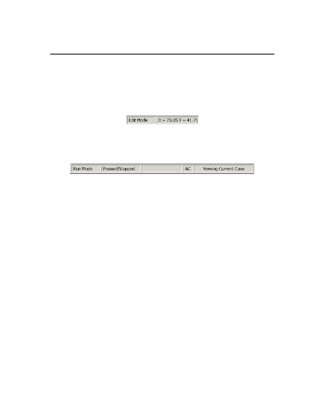
The Status Bar is displayed across the bottom of the PowerWorld Simulator window. The left-most field of the status
bar displays the current Simulator mode (Edit or Run). The remaining fields vary depending on which mode of
operation Simulator is currently in. The status bar displays Tool Tips when the cursor is positioned over a toolbar
button or menu item. The tool tip is also shown next to the cursor after a short time delay. To change the display of
tool tips, see Customizing the Toolbars.
Edit Mode
The Edit Mode status bar displays the Screen Coordinates of the cursor when positioned over a oneline diagram.
Edit Mode Status Bar
Run Mode
The Left side of the Run Mode status bar displays simulation status ("Paused/Stopped" or "Running"), AC or DC
depending on solution options and the Difference Flows status ("Current Case", "Base Case", or "Difference Case").
Run Mode Status Bar (Left Side)
17
Toolbars
Using the Toolbars
Simulator 11.0 makes extensive use of toolbars for easy access to its many features. You can move and size these
toolbars according to your preferences. The toolbars house several controls, each of which can be activated with a
single mouse click. Simulator provides several customizable toolbars that group commonly used functionality. Many
of these toolbars are displayed by default, with certain toolbars available only in Edit mode or Run mode respectively.
To display or hide toolbars select the Window > Toolbars menu option or right-click in the toolbar docking area near
the top of the oneline diagram. The Toolbars available in Simulator are:
· Main Menu Toolbar
· File Toolbar
· Program Toolbar
· Options/Info Toolbar
· Zoom Toolbar
· Format Toolbar
· Edit Toolbar
· Case Information Toolbar
· Insert Toolbar
· Pie Chart Options Toolbar
· Animated Flow Options Toolbar
· Contour Options Toolbar
· Solution Options Toolbar
· Thumbnail View Options Toolbar
· Oneline Options Toolbar
· Run Mode Toolbar
· Time Step Simulation Toolbar
18

Getting Started With PowerWorld
Main Menu Toolbar
The Main Menu toolbar provides access to the main menus of the program, such as File, Edit, Insert, Windows, and
Help. The default items displayed on the Main Menu vary based whether you are in Edit mode or Run mode. The
displayed Main Menu items also depend on which PowerWorld Simulator Add-on Tools are installed. This toolbar is
always visible, but it can be customized just like any other toolbar in Simulator. The drop-down menus can also be
customized to add additional options or remove the default options.
19
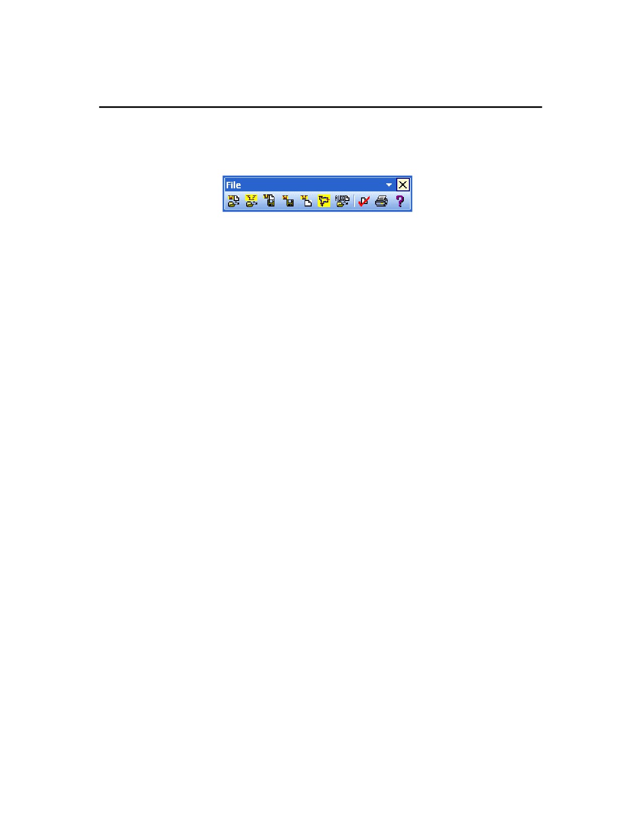
File Toolbar
The File Toolbar provides access to operating system activities such as saving a oneline diagram or case model to
disk, printing a oneline display to a printer, or loading a case or oneline from disk. This toolbar also offers access to
the on-line help system and to PowerWorld’s case validation tool
This toolbar contains the following default buttons, in order from left to right:
· Open Case
· Open Oneline
· Save Case
· Save Oneline
· New Case
· New Oneline
· Load Auxiliary File
· Validate Case
· Print Window
· Help
20
///////////////////////////////////////