TMS320C6000 Assembly Language Tools v 6.1. User's Guide - page 6
Chapter 8
Absolute Lister Description
The TMS320C6000™ absolute lister is a debugging tool that accepts linked object files as input and
creates .abs files as output. These .abs files can be assembled to produce a listing that shows the
absolute addresses of object code. Manually, this could be a tedious process requiring many operations;
however, the absolute lister utility performs these operations automatically.
Absolute Listing Is Not Supported for C6400+ and C6740
Note: The absolute listing capability is not supported for C6400+ and C6740. You can use the
disassembler (dis6x) or the --map_file linker option instead.
Topic
Page
8.1
Producing an Absolute Listing
212
8.2
Invoking the Absolute Lister
213
8.3
Absolute Lister Example
214
Absolute Lister Description
211
Producing an Absolute Listing
8.1
Producing an Absolute Listing
Figure
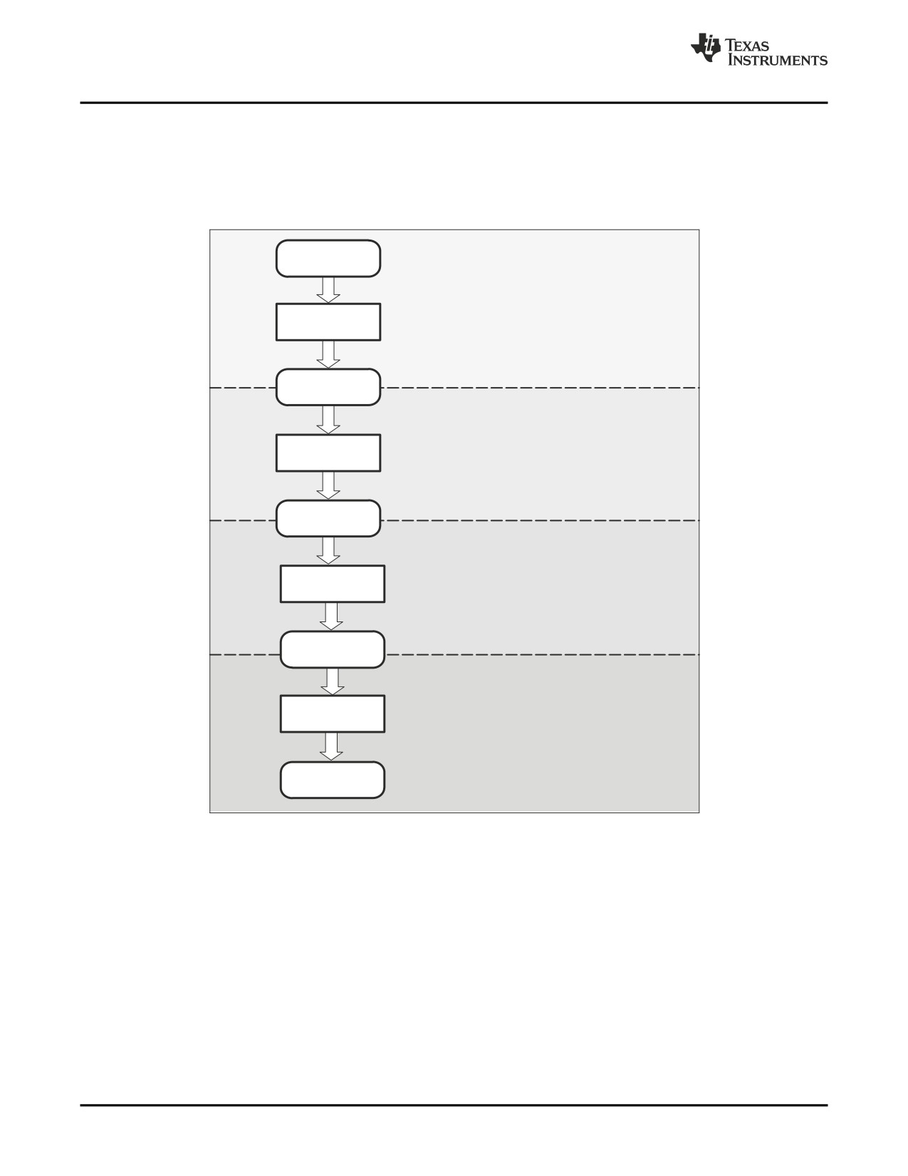
8-1 illustrates the steps required to produce an absolute listing.
Figure 8-1. Absolute Lister Development Flow
Assembler
Step 1:
First, assemble a source file.
source file
ÍÍ
ÍÍ
Assembler
ÍÍ
Object
file
Step 2:
ÍÍ
Link the resulting object file.
ÍÍ
Linker
ÍÍ
ÍÍ
Linked object
file
Step 3:
ÍÍ
Invoke the absolute lister; use the linked ob-
ject file as input. This creates a file with an .abs
ÍÍ
Absolute
extension.
lister
ÍÍ
ÍÍ
.abs
file
Step 4:
ÍÍ
Finally, assemble the .abs file; you must in-
voke the assembler with the −a option. This
Assembler
produces a listing file that contains absolute
addresses.
ÍÍ
bsolute
listing
212
Absolute Lister Description
Invoking the Absolute Lister
8.2
Invoking the Absolute Lister
The syntax for invoking the absolute lister is:
abs6x [-options] input file
abs6x
is the command that invokes the absolute lister.
options
identifies the absolute lister options that you want to use. Options are not case sensitive
and can appear anywhere on the command line following the command. Precede each
option with a hyphen (-). The absolute lister options are as follows:
-e enables you to change the default naming conventions for filename extensions on
assembly files, C source files, and C header files. The valid options are:
• ea [.]asmext for assembly files (default is .asm)
• ec [.]cext for C source files (default is .c)
• eh [.]hext for C header files (default is .h)
• ep [.]pext for CPP source files (default is cpp)
The . in the extensions and the space between the option and the extension are
optional.
-q
(quiet) suppresses the banner and all progress information.
input file
names the linked object file. If you do not supply an extension, the absolute lister
assumes that the input file has the default extension .out. If you do not supply an input
filename when you invoke the absolute lister, the absolute lister prompts you for one.
The absolute lister produces an output file for each file that was linked. These files are named with the
input filenames and an extension of .abs. Header files, however, do not generate a corresponding .abs
file.
Assemble these files with the --absolute_listing assembler option as follows to create the absolute listing:
cl6x --absolute_listing filename.abs
The -e options affect both the interpretation of filenames on the command line and the names of the
output files. They should always precede any filename on the command line.
The -e options are useful when the linked object file was created from C files compiled with the debugging
option (--symdebug:dwarf compiler option). When the debugging option is set, the resulting linked object
file contains the name of the source files used to build it. In this case, the absolute lister does not generate
a corresponding .abs file for the C header files. Also, the .abs file corresponding to a C source file uses
the assembly file generated from the C source file rather than the C source file itself.
For example, suppose the C source file hello.csr is compiled with the debugging option set; the debugging
option generates the assembly file hello.s. The hello.csr file includes hello.hsr. Assuming the executable
file created is called hello.out, the following command generates the proper .abs file:
abs6x
-ea s
-ec csr
-eh hsr hello.out
An .abs file is not created for hello.hsr (the header file), and hello.abs includes the assembly file hello.s,
not the C source file hello.csr.
Absolute Lister Description
213
Absolute Lister Example
8.3
Absolute Lister Example
This example uses three source files. The files module1.asm and module2.asm both include the file
globals.def.
module1.asm
.text
.align
4
.bss
array, 100
.bss
dflag, 4
.copy
globals.def
MVKL
offset, A0
MVKH
offset, A0
LDW
*+b14(dflag), A2
nop
4
module2.asm
.bss offset,2
.copy globals.def
mvkl
offset,a0
mvkh
offset,a0
mvkl
array,a3
mvkh
array,a3
globals.def
.global dflag
.global array
.global offset
The following steps create absolute listings for the files module1.asm and module2.asm:
1. First, assemble module1.asm and module2.asm:
cl6x module1
cl6x module2
This creates two object files called module1.obj and module2.obj.
2. Next, link module1.obj and module2.obj using the following linker command file, called bttest.cmd:
--output_file=bttest.out
--map_file=bttest.map
module1.obj
module2.obj
MEMORY
{
PMEM:
origin=00000000h
length=00010000h
DMEM:
origin=80000000h
length=00010000h
}
SECTIONS
{
.data: >DMEM
.text: >PMEM
.bss:
>DMEM
}
Invoke the linker:
cl6x
--run_linker bttest.cmd
This command creates an executable object file called bttest.out; use this new file as input for the
absolute lister.
214
Absolute Lister Description
Absolute Lister Example
3.
Now, invoke the absolute lister:
abs6x bttest.out
This command creates two files called module1.abs and module2.abs:
module1.abs:
.nolist
array
.setsym
080000000h
dflag
.setsym
080000064h
offset
.setsym
080000068h
.data
.setsym
080000000h
___data__
.setsym
080000000h
edata
.setsym
080000000h
___edata__
.setsym
080000000h
.text
.setsym
000000000h
___text__
.setsym
000000000h
etext
.setsym
000000040h
___etext__
.setsym
000000040h
.bss
.setsym
080000000h
___bss__
.setsym
080000000h
end
.setsym
08000006ah
___end__
.setsym
08000006ah
$bss
.setsym
080000000h
.setsect
".text",000000020h
.setsect
".data",080000000h
.setsect
".bss",080000000h
.list
.text
.copy
"module1.asm"
Absolute Lister Description
215
Absolute Lister Example
module2.abs:
.nolist
array
.setsym
080000000h
dflag
.setsym
080000064h
offset
.setsym
080000068h
.data
.setsym
080000000h
___data__
.setsym
080000000h
edata
.setsym
080000000h
___edata__
.setsym
080000000h
.text
.setsym
000000000h
___text__
.setsym
000000000h
etext
.setsym
000000040h
___etext__
.setsym
000000040h
.bss
.setsym
080000000h
___bss__
.setsym
080000000h
end
.setsym
08000006ah
___end__
.setsym
08000006ah
$bss
.setsym
080000000h
.setsect
".text",000000000h
.setsect
".data",080000000h
.setsect
".bss",080000068h
.list
.text
.copy
"module2.asm"
These files contain the following information that the assembler needs for step 4:
• They contain .setsym directives, which equate values to global symbols. Both files contain global
equates for the symbol dflag. The symbol dflag was defined in the file globals.def, which was
included in module1.asm and module2.asm.
• They contain .setsect directives, which define the absolute addresses for sections.
• They contain .copy directives, which defines the assembly language source file to include.
The .setsym and .setsect directives are useful only for creating absolute listings, not normal assembly.
4.
Finally, assemble the .abs files created by the absolute lister (remember that you must use the
--absolute_listing option when you invoke the assembler):
cl6x
--absolute_listing module1.abs
cl6x
--absolute_listing module2.abs
This command sequence creates two listing files called module1.lst and module2.lst; no object code is
produced. These listing files are similar to normal listing files; however, the addresses shown are
absolute addresses.
The absolute listing files created are module1.lst (see Example 8-1 ) and module2.lst (see Example
8-2).
216
Absolute Lister Description
Absolute Lister Example
Example 8-1. module1.lst
TMS320C6x COFF Assembler
Version x.xx
Mon Jan
5 11:34:00 1998
Copyright (c) 1996-1998 Texas Instruments Incorporated
module1.abs
PAGE
1
22 00000020
.text
23
.copy
"module1.asm"
A
1 00000020
.text
A
2
.align
4
A
3 80000000
.bss
array, 100
A
4 80000064
.bss
dflag, 4
A
5
.copy
globals.def
B
1
.global dflag
B
2
.global array
B
3
.global offset
A
6
A
7 00000020 00003428!
MVKL
offset, A0
A
8 00000024 00400068!
MVKH
offset, A0
A
9 00000028 0100196C-
LDW
*+b14(dflag), A2
A
10 0000002c 00006000
nop
4
No Errors, No Warnings
Example 8-2. module2.lst
TMS320C6x COFF Assembler
Version x.xx
Mon Jan
5 11:34:05 1998
Copyright (c) 1996-1998 Texas Instruments Incorporated
module2.abs
PAGE
1
22 00000000
.text
23
.copy
"module2.asm"
A
1 80000068
.bss offset,2
A
2
.copy globals.def
B
1
.global dflag
B
2
.global array
B
3
.global offset
A
3
A
4 00000000 00003428-
mvkl
offset,a0
A
5 00000004 00400068-
mvkh
offset,a0
A
6 00000008 01800028!
mvkl
array,a3
A
7 0000000c 01C00068!
mvkh
array,a3
No Errors, No Warnings
Absolute Lister Description
217
218
Absolute Lister Description
Chapter 9
Cross-Reference Lister Description
The TMS320C6000™ cross-reference lister is a debugging tool. This utility accepts linked object files as
input and produces a cross-reference listing as output. This listing shows symbols, their definitions, and
their references in the linked source files.
Cross-Reference Listing Not Supported for C6400+ and C6740
Note: The cross-reference listing capability is not supported for C6400+ and C6740. You can use
the disassembler, the -m linker option or the object file utility (ofd6x) to obtain similar
information.
Topic
Page
9.1
Producing a Cross-Reference Listing
220
9.2
Invoking the Cross-Reference Lister
221
9.3
Cross-Reference Listing Example
221
Cross-Reference Lister Description
219
Producing a Cross-Reference Listing
9.1
Producing a Cross-Reference Listing
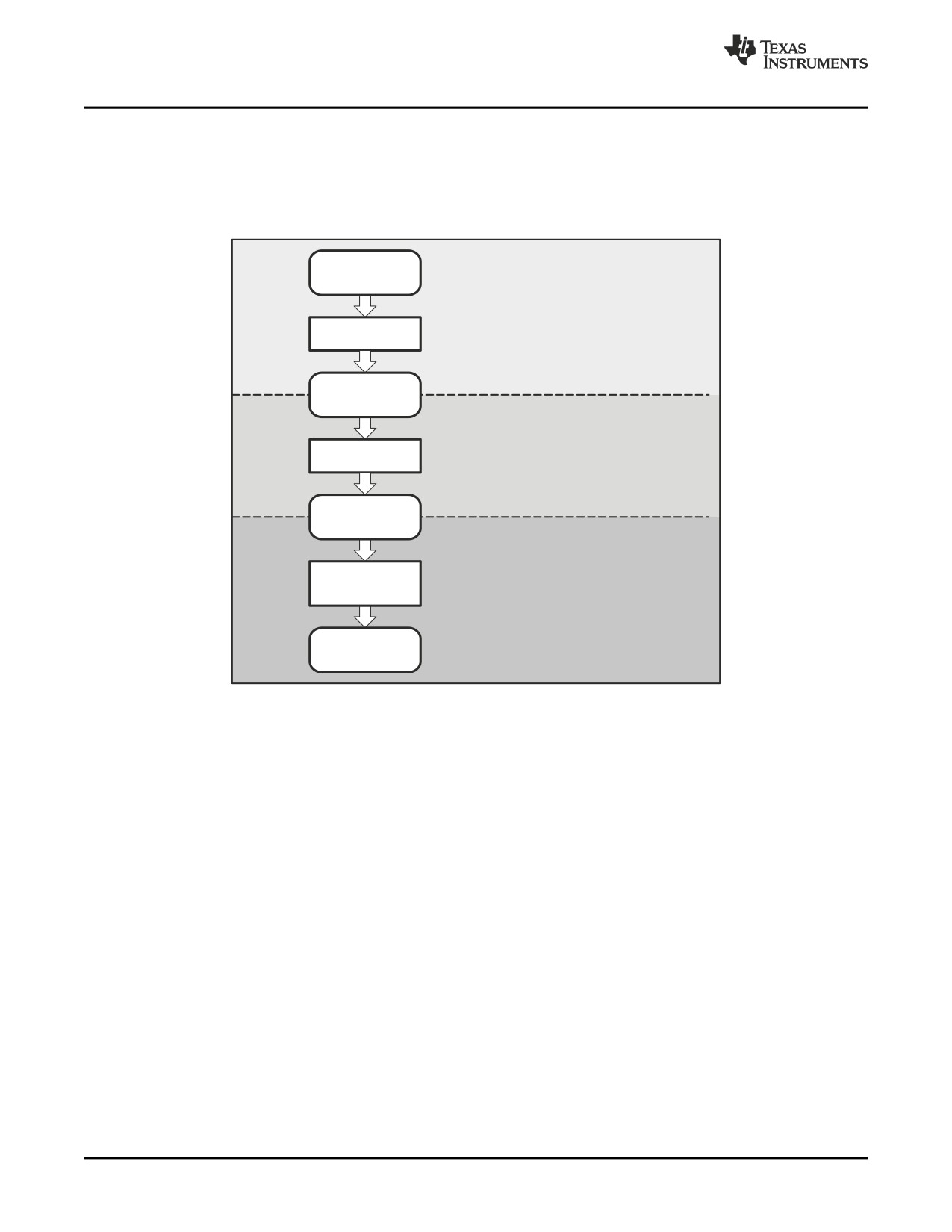
Figure 9-1 illustrates the steps required to produce a cross-reference listing.
Figure 9-1. The Cross-Reference Lister in the TMS320C6000 Software Development Flow
Step 1:
Assembler
First, invoke the assembler with the -ax option.
source file
This option produces a cross-reference table
in the listing file and adds to the object file
cross-reference information. By default, the
Assembler
assembler cross-references only global
symbols. If you use the -as option when
invoking the assembler, it cross-references
local symbols as well.
Object
file
Step 2:
Link the object file (.obj) to obtain an
executable object file (.out).
Link step
Linked object
file
Step 3:
Invoke the cross-reference lister. The following
section provides the command syntax for
Cross-reference
invoking the cross-reference lister utility.
lister
Cross-reference
listing
220
Cross-Reference Lister Description
Invoking the Cross-Reference Lister
9.2
Invoking the Cross-Reference Lister
To use the cross-reference utility, the file must be assembled with the correct options and then linked into
an executable file. Assemble the assembly language files with the --cross_reference option. This option
creates a cross-reference listing and adds cross-reference information to the object file. By default, the
assembler cross-references only global symbols, but if the assembler is invoked with the
--output_all_syms option, local symbols are also added. Link the object files to obtain an executable file.
To invoke the cross-reference lister, enter the following:
xref6x [options] [input filename [output filename]]
xref6x
is the command that invokes the cross-reference utility.
options
identifies the cross-reference lister options you want to use. Options are not case
sensitive and can appear anywhere on the command line following the command.
-l
(lowercase L) specifies the number of lines per page for the output file. The format
of the -l option is -lnum, where num is a decimal constant. For example, -l30 sets
the number of lines per page in the output file to 30. The space between the
option and the decimal constant is optional. The default is 60 lines per page.
-q suppresses the banner and all progress information (run quiet).
input filename is a linked object file. If you omit the input filename, the utility prompts for a filename.
output filename is the name of the cross-reference listing file. If you omit the output filename, the default
filename is the input filename with an .xrf extension.
9.3
Cross-Reference Listing Example
Example 9-1 is an example of cross-reference listing.
Example 9-1. Cross-Reference Listing
================================================================================
Symbol: _SETUP
Filename
RTYP
AsmVal
LnkVal
DefLn
RefLn
RefLn
RefLn
________
____
________
________
______
_______
_______
_______
demo.asm
EDEF '00000018
00000018
18
13
20
================================================================================
Symbol: _fill_tab
Filename
RTYP
AsmVal
LnkVal
DefLn
RefLn
RefLn
RefLn
________
____
________
________
______
_______
_______
_______
ctrl.asm
EDEF '00000000
00000040
10
5
================================================================================
Symbol: _x42
Filename
RTYP
AsmVal
LnkVal
DefLn
RefLn
RefLn
RefLn
________
____
________
________
______
_______
_______
_______
demo.asm
EDEF '00000000
00000000
7
4
18
================================================================================
Symbol: gvar
Filename
RTYP
AsmVal
LnkVal
DefLn
RefLn
RefLn
RefLn
________
____
________
________
______
_______
_______
_______
tables.asm
EDEF "00000000
08000000
11
10
================================================================================
Cross-Reference Lister Description
221
Cross-Reference Listing Example
The terms defined below appear in the preceding cross-reference listing:
Symbol
Name of the symbol listed
Filename
Name of the file where the symbol appears
RTYP
The symbol's reference type in this file. The possible reference types are:
STAT The symbol is defined in this file and is not declared as global.
EDEF The symbol is defined in this file and is declared as global.
EREF The symbol is not defined in this file but is referenced as global.
UNDF The symbol is not defined in this file and is not declared as global.
AsmVal
This hexadecimal number is the value assigned to the symbol at assembly time. A
value may also be preceded by a character that describes the symbol's attributes.
Table 9-1 lists these characters and names.
LnkVal
This hexadecimal number is the value assigned to the symbol after linking.
DefLn
The statement number where the symbol is defined.
RefLn
The line number where the symbol is referenced. If the line number is followed by an
asterisk (*), then that reference can modify the contents of the object. A blank in this
column indicates that the symbol was never used.
Table 9-1. Symbol Attributes in Cross-Reference
Listing
Character
Meaning
'
Symbol defined in a .text section
"
Symbol defined in a .data section
+
Symbol defined in a .sect section
-
Symbol defined in a .bss or .usect section
222
Cross-Reference Lister Description
Chapter 10
Object File Utilities Descriptions
This chapter describes how to invoke the following miscellaneous utilities:
• The object file display utility prints the contents of object files, executable files, and/or archive
libraries in both text and XML formats.
• The disassembler writes the disassembled object code from object or executable files.
• The name utility prints a list of names defined and referenced in an object or executable file.
• The strip utility removes symbol table and debugging information from object and executable files.
Topic
Page
10.1
Invoking the Object File Display Utility
224
10.2
Invoking the Disassembler
225
10.3
Invoking the Name Utility
226
10.4
Invoking the Strip Utility
227
Object File Utilities Descriptions
223
Invoking the Object File Display Utility
10.1
Invoking the Object File Display Utility
The object file display utility, ofd6x, prints the contents of object files (.obj), executable files (.out), and/or
archive libraries (.lib) in both text and XML formats.
To invoke the object file display utility, enter the following:
ofd6x [options] input filename [input filename]
ofd6x
is the command that invokes the object file display utility.
input filename
names the object file (.obj), executable file (.out), or archive library (.lib) source file.
The filename must contain an extension.
options
identify the object file display utility options that you want to use. Options are not case
sensitive and can appear anywhere on the command line following the command.
Precede each option with a hyphen.
--dwarf_display=attributes
controls the DWARF display filter settings by specifying a
comma-delimited list of attributes. When prefixed with no,
an attribute is disabled instead of enabled.
Examples:
--dwarf_display=nodabbrev,nodline
--dwarf_display=all,nodabbrev
--dwarf_display=none,dinfo,types
The ordering of attributes is important (see --obj_display).
The list of available display attributes can be obtained by
invoking ofd6x --dwarf_display=help.
--dynamic_info
outputs dynamic linking information for ELF only.
-g
appends DWARF debug information to program output.
-h
displays help
-o=filename
sends program output to filename rather than to the
screen.
--obj_display attributes
controls the object file display filter settings by specifying
a comma-delimited list of attributes. When prefixed with
no, an attribute is disabled instead of enabled.
Examples:
--obj_display=rawdata,nostrings
--obj_display=all,norawdata
--obj_display=none,header
The ordering of attributes is important. For instance, in
"--obj_display=none,header", ofd6x disables all output,
then re-enables file header information. If the attributes
are specified in the reverse order, (header,none), the file
header is enabled, the all output is disabled, including the
file header. Thus, nothing is printed to the screen for the
given files. The list of available display attributes can be
obtained by invoking ofd6x --obj_display=help.
-v
prints verbose text output.
-x
displays output in XML format.
--xml_indent=num
sets the number of spaces to indent nested XML tags.
224
Object File Utilities Descriptions
Invoking the Disassembler
If an archive file is given as input to the object file display utility, each object file member of the archive is
processed as if it was passed on the command line. The object file members are processed in the order in
which they appear in the archive file.
If the object file display utility is invoked without any options, it displays information about the contents of
the input files on the console screen.
Object File Display Format
Note: The object file display utility produces data in a text format by default. This data is not
intended to be used as machine or software input.
10.2
Invoking the Disassembler
The disassembler, dis6x, examines the output of the assembler or linker. This utility accepts an object file
or executable file as input and writes the disassembled object code to standard output or a specified file.
To invoke the disassembler, enter the following:
dis6x [options] input filename[.ext] [output filename]
dis6x
is the command that invokes the disassembler.
options
identifies the name utility options you want to use. Options are not case sensitive and
can appear anywhere on the command line following the invocation. Precede each
option with a hyphen (-). The name utility options are as follows:
-a
disables printing of branch destination address along with label
-b
displays data as bytes instead of words
-c
dumps the object file information.
-d
disables display of data sections.
-h
shows the current help screen.
-i
disassembles .data sections as instructions.
-n
suppresses FP header information for Joule Compact FPs
-o ##
disassembles single word ## or 0x## then exits
-q
(quiet mode) suppresses the banner and all progress information.
-qq
(super quiet mode) suppresses all headers.
-s
suppresses printing of address and data words.
-t
disables display of text sections
input
is the name of the input file. If the optional extension is not specified, the file is
filename[.ext]
searched for in this order:
1. infile
2. infile.out, an executable file
3. infile.obj, an object file
output filename
is the name of the optional output file to which the disassembly will be written. If an
output filename is not specified, the disassembly is written to standard output.
Object File Utilities Descriptions
225
Invoking the Name Utility
10.3
Invoking the Name Utility
The name utility, nm6x, prints the list of names defined and referenced in an object (.obj) or an executable
file (.out). It also prints the symbol value and an indication of the kind of symbol.
To invoke the name utility, enter the following:
nm6x [-options] [input filenames]
nm6x
is the command that invokes the name utility.
input filename
is an object file (.obj) or an executable file (.out).
options
identifies the name utility options you want to use. Options are not case sensitive and
can appear anywhere on the command line following the invocation. Precede each
option with a hyphen (-). The name utility options are as follows:
-a
prints all symbols.
-c
also prints C_NULL symbols for a COFF object module.
-d
also prints debug symbols for a COFF object module.
-f
prepends file name to each symbol.
-g
prints only global symbols.
-h
shows the current help screen.
-l
produces a detailed listing of the symbol information.
-n
sorts symbols numerically rather than alphabetically.
-o file
outputs to the given file.
-p
causes the name utility to not sort any symbols.
-q
(quiet mode) suppresses the banner and all progress information.
-r
sorts symbols in reverse order.
-s
lists symbols in the dynamic symbol table for an ELF object module.
-t
also prints tag information symbols for a COFF object module.
-u
only prints undefined symbols.
226
Object File Utilities Descriptions
Invoking the Strip Utility
10.4
Invoking the Strip Utility
The strip utility, strip6x, removes symbol table and debugging information from object and executable files.
To invoke the strip utility, enter the following:
strip6x [-p] input filename [input filename]
strip6x
is the command that invokes the strip utility.
input filename is an object file (.obj) or an executable file (.out).
options
identifies the strip utility options you want to use. Options are not case sensitive and can
appear anywhere on the command line following the invocation. Precede each option
with a hyphen (-). The strip utility option is as follows:
-o filename writes the stripped output to filename.
-p
removes all information not required for execution. This option causes more
information to be removed than the default behavior, but the object file is
left in a state that cannot be linked. This option should be used only with
executable (.out) files.
When the strip utility is invoked without the -o option, the input object files are replaced with the stripped
version.
Object File Utilities Descriptions
227
228
Object File Utilities Descriptions
Chapter 11
Hex Conversion Utility Description
The TMS320C6000™ assembler and linker create object files which are in binary formats that encourage
modular programming and provide powerful and flexible methods for managing code segments and target
system memory.
Most EPROM programmers do not accept object files as input. The hex conversion utility converts an
object file into one of several standard ASCII hexadecimal formats, suitable for loading into an EPROM
programmer. The utility is also useful in other applications requiring hexadecimal conversion of an object
file (for example, when using debuggers and loaders).
The hex conversion utility can produce these output file formats:
• ASCII-Hex, supporting 32-bit addresses
• Extended Tektronix (Tektronix)
• Intel MCS-86 (Intel)
• Motorola Exorciser (Motorola-S), supporting 16-bit addresses
• Texas Instruments SDSMAC (TI-Tagged), supporting 16-bit addresses
Topic
Page
11.1
The Hex Conversion Utility's Role in the Software Development
Flow
230
11.2
Invoking the Hex Conversion Utility
231
11.3
Understanding Memory Widths
234
11.4
The ROMS Directive
238
11.5
The SECTIONS Directive
242
11.6
Excluding a Specified Section
243
11.7
Assigning Output Filenames
244
11.8
Image Mode and the -fill Option
245
11.9
Building a Table for an On-Chip Boot Loader
246
11.10
Controlling the ROM Device Address
249
11.11
Description of the Object Formats
250
Hex Conversion Utility Description
229
The Hex Conversion Utility's Role in the Software Development Flow
11.1
The Hex Conversion Utility's Role in the Software Development Flow
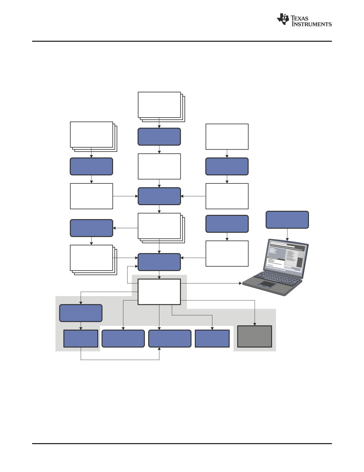
Figure 11-1 highlights the role of the hex conversion utility in the software development process.
Figure 11-1. The Hex Conversion Utility in the TMS320C6000 Software Development Flow
C/C++
source
files
Macro
source
C/C++
Linear
files
compiler
assembly
Assembler
Assembly
Archiver
source
optimizer
Assembly
Macro
Assembler
optimized
library
file
Debugging
Library-build
Object
tools
process
Archiver
files
Run-time-
Library of
support
object
library
Linker
files
Executable
object file
Hex-conversion
utility
EPROM
Cross-reference
Object file
C6000
Absolute lister
programmer
lister
utilities
230
Hex Conversion Utility Description
Invoking the Hex Conversion Utility
11.2
Invoking the Hex Conversion Utility
There are two basic methods for invoking the hex conversion utility:
• Specify the options and filenames on the command line. The following example converts the file
firmware.out into TI-Tagged format, producing two output files, firm.lsb and firm.msb.
hex6x -t firmware -o firm.lsb -o firm.msb
• Specify the options and filenames in a command file. You can create a batch file that stores
command line options and filenames for invoking the hex conversion utility. The following example
invokes the utility using a command file called hexutil.cmd:
hex6x hexutil.cmd
In addition to regular command line information, you can use the hex conversion utility ROMS and
SECTIONS directives in a command file.
11.2.1
Invoking the Hex Conversion Utility From the Command Line
To invoke the hex conversion utility, enter:
hex6x [options] filename
hex6x
is the command that invokes the hex conversion utility.
options
supplies additional information that controls the hex conversion process. You can use
options on the command line or in a command file. Table 11-1 lists the basic options.
• All options are preceded by a hyphen and are not case sensitive.
• Several options have an additional parameter that must be separated from the option
by at least one space.
• Options with multicharacter names must be spelled exactly as shown in this document;
no abbreviations are allowed.
• Options are not affected by the order in which they are used. The exception to this rule
is the -q (quiet) option, which must be used before any other options.
filename
names an object file or a command file (for more information, see Section 11.2.2). If you
do not specify a filename, the utility prompts you for one.
Hex Conversion Utility Description
231
Invoking the Hex Conversion Utility
Table 11-1. Basic Hex Conversion Utility Options
General Options
Option
Description
See
Control the overall operation of
-exclude=section_name
Ignore specified section
Section 11.6
the hex conversion utility.
-linkerfill
Include linker fill sections in images
-map=filename
Generate a map file
Section 11.4.2
-o=filename
Specify an output filename
Section 11.7
-quiet, -q
Run quietly (when used, it must appear before
Section 11.2.2
other options)
Image Options
Option
Description
See
Create a continuous image of a
-fill=value
Fill holes with value
Section 11.8.2
range of target memory
-image
Specify image mode
Section 11.8.1
-zero
Reset the address origin to 0 in image mode
Section 11.8.3
Memory Options
Option
Description
See
Configure the memory widths for
-memwidth=value
Define the system memory word width (default
Section 11.3.2
your output files
32 bits)
-order=L
Output file is in little-endian format
Section 11.3.4
-order=M
Output file is in big-endian format
Section 11.3.4
-romwidth=value
Specify the ROM device width (default
Section 11.3.3
depends on format used)
Output Options
Option
Description
See
Specify the output format
-a
Select ASCII-Hex
Section 11.11.1
-i
Select Intel
Section 11.11.2
-m
Select Motorola-S
Section 11.11.3
-t
Select TI-Tagged
Section 11.11.4
--ti_txt
Select TI-Txt
Section 11.11.5
-x
Select Tektronix (default)
Section 11.11.6
Boot Options
Option
Description
See
Control the boot loader
-boot
Convert all initialized sections into bootable
form (use instead of a SECTIONS directive)
-bootorg=addr
Specify origin address of the boot loader table
-bootsection sectname value
Specify which section contains the boot
routine and where it should be placed
-e value
Specify the entry point address or global
symbol at which to begin execution after boot
loading.
232
Hex Conversion Utility Description
Invoking the Hex Conversion Utility
11.2.2
Invoking the Hex Conversion Utility With a Command File
A command file is useful if you plan to invoke the utility more than once with the same input files and
options. It is also useful if you want to use the ROMS and SECTIONS hex conversion utility directives to
customize the conversion process.
Command files are ASCII files that contain one or more of the following:
• Options and filenames. These are specified in a command file in exactly the same manner as on the
command line.
• ROMS directive. The ROMS directive defines the physical memory configuration of your system as a
list of address-range parameters. (See Section 11.4.)
• SECTIONS directive. The hex conversion utility SECTIONS directive specifies which sections from the
object file are selected. (See Section 11.5.)
• Comments. You can add comments to your command file by using the /* and */ delimiters. For
example:
/*
This is a comment.
*/
To invoke the utility and use the options you defined in a command file, enter:
hex6x command_filename
You can also specify other options and files on the command line. For example, you could invoke the
utility by using both a command file and command line options:
hex6x firmware.cmd -map firmware.mxp
The order in which these options and filenames appear is not important. The utility reads all input from the
command line and all information from the command file before starting the conversion process. However,
if you are using the -q option, it must appear as the first option on the command line or in a command file.
The -q option suppresses the hex conversion utility's normal banner and progress information.
• Assume that a command file named firmware.cmd contains these lines:
firmware.out
/* input file
*/
-t
/* TI-Tagged
*/
-o
firm.lsb
/* output file */
-o
firm.msb
/* output file */
You can invoke the hex conversion utility by entering:
hex6x firmware.cmd
• This example shows how to convert a file called appl.out into eight hex files in Intel format. Each output
file is one byte wide and 4K bytes long.
appl.out
/* input file
*/
-I
/* Intel format */
-map appl.mxp
/* map file
*/
ROMS
{
ROW1: origin=0x00000000 len=0x4000 romwidth=8
files={ appl.u0 appl.u1 app1.u2 appl.u3 }
ROW2: origin=0x00004000 len=0x4000 romwidth=8
files={ app1.u4 appl.u5 appl.u6 appl.u7 }
}
SECTIONS
{
.text, .data, .cinit, .sect1, .vectors, .const:
}
Hex Conversion Utility Description
233
Understanding Memory Widths
11.3
Understanding Memory Widths
The hex conversion utility makes your memory architecture more flexible by allowing you to specify
memory and ROM widths. To use the hex conversion utility, you must understand how the utility treats
word widths. Three widths are important in the conversion process:
• Target width
• Memory width
• ROM width
The terms target word, memory word, and ROM word refer to a word of such a width.
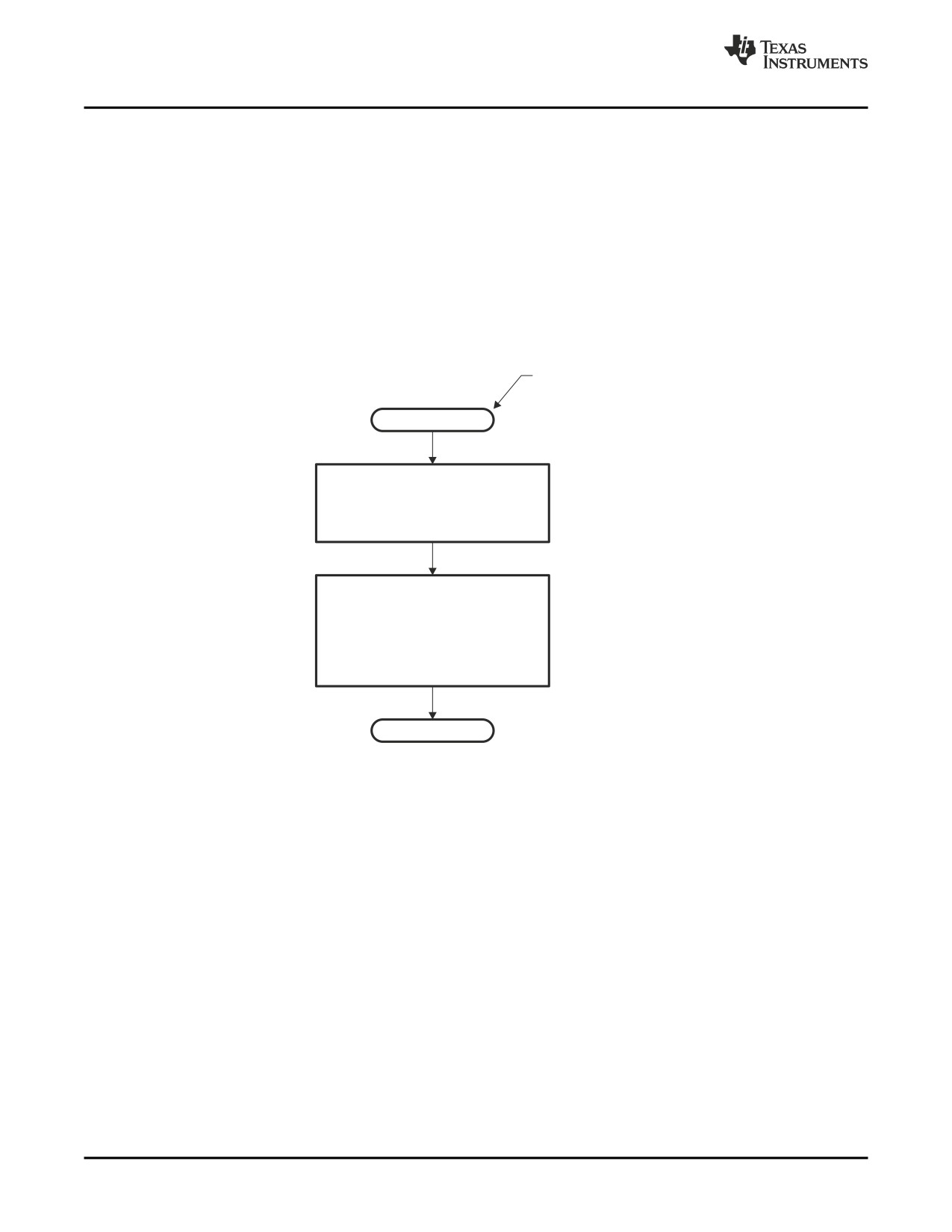
Figure 11-2 illustrates the two separate and distinct phases of the hex conversion utility's process flow.
Figure 11-2. Hex Conversion Utility Process Flow
Raw data in object files is
represented in the target’s
addressable units. For the
Input file
C6000, this is 32 bits.
The raw data in the object file
is grouped into words according
Phase I
to the size specified by the
-memwidth option.
The memwidth-sized words are
broken up according to the size
specified by the -romwidth option
Phase II
and are written to a file(s)
according to the specified format
(i.e., Intel, Tektronix, etc.).
Output file(s)
11.3.1
Target Width
Target width is the unit size (in bits) of the target processor's word. The unit size corresponds to the data
bus size on the target processor. The width is fixed for each target and cannot be changed. The
TMS320C6000 targets have a width of 32 bits.
234
Hex Conversion Utility Description
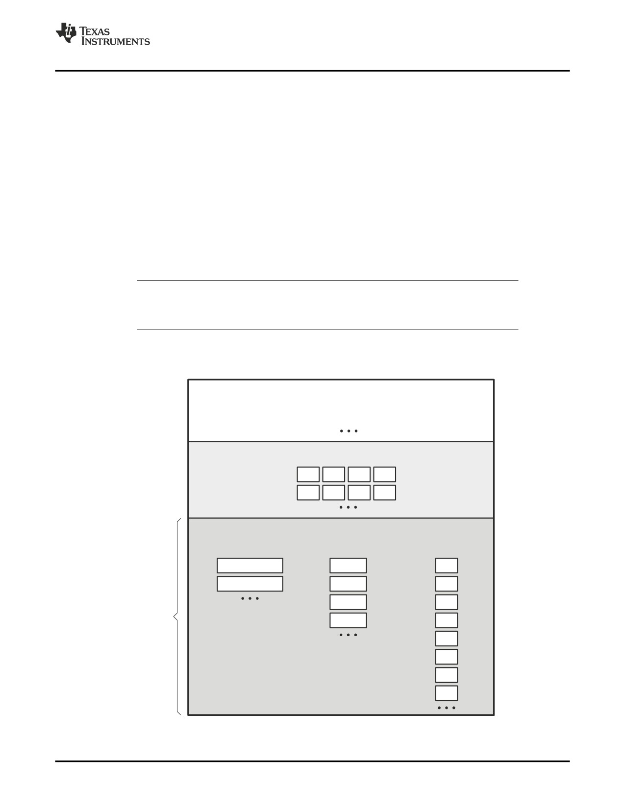
Understanding Memory Widths
11.3.2
Specifying the Memory Width
Memory width is the physical width (in bits) of the memory system. Usually, the memory system is
physically the same width as the target processor width: a 32-bit processor has a 32-bit memory
architecture. However, some applications require target words to be broken into multiple, consecutive, and
narrower memory words.
By default, the hex conversion utility sets memory width to the target width (in this case, 32 bits).
You can change the memory width (except for TI-TXT format) by:
• Using the -memwidth option. This changes the memory width value for the entire file.
• Setting the memwidth parameter of the ROMS directive. This changes the memory width value for the
address range specified in the ROMS directive and overrides the -memwidth option for that range. See
Section 11.4.
For both methods, use a value that is a power of 2 greater than or equal to 8.
You should change the memory width default value of 32 only when you need to break single target words
into consecutive, narrower memory words.
TI-TXT Format is 8 Bits Wide
Note: You cannot change the memory width of the TI-TXT format. The TI-TXT hex format supports
an 8-bit memory width only.
Figure
11-3 demonstrates how the memory width is related to object file data.
Figure 11-3. Object File Data and Memory Widths
Source file
.word
0AABBCCDDh
.word
011223344h
Object file data (assumed to be in little-endian format)
AA
BB
CC
DD
11
22
33
44
Memory widths (variable)
-memwidth 32 (default)
-memwidth 16
-memwidth 8
AABBCCDD
CCDD
DD
11223344
AABB
CC
Data after
3344
BB
phase I
1122
AA
of hex6x
44
33
22
11
Hex Conversion Utility Description
235
Understanding Memory Widths
11.3.3
Partitioning Data Into Output Files
ROM width specifies the physical width (in bits) of each ROM device and corresponding output file
(usually one byte or eight bits). The ROM width determines how the hex conversion utility partitions the
data into output files. After the object file data is mapped to the memory words, the memory words are
broken into one or more output files. The number of output files is determined by the following formulas:
• If memory width ≥ ROM width:
number of files = memory width ÷ ROM width
• If memory width < ROM width:
number of files = 1
For example, for a memory width of 32, you could specify a ROM width value of 32 and get a single
output file containing 32 bits words. Or you can use a ROM width value of 16 to get two files, each
containing 16 bits of each word.
The default ROM width that the hex conversion utility uses depends on the output format:
• All hex formats except TI-Tagged are configured as lists of 8-bit bytes; the default ROM width for these
formats is 8 bits.
• TI-Tagged is a 16-bit format; the default ROM width for TI-Tagged is 16 bits.
The TI-Tagged Format is 16 Bits Wide
Note: You cannot change the ROM width of the TI-Tagged format. The TI-Tagged format supports
a 16-bit ROM width only.
TI-TXT Format is 8 Bits Wide
Note: You cannot change the memory width of the TI-TXT format. The TI-TXT hex format supports
an 8-bit memory width only.
You can change ROM width (except for TI-Tagged format) by:
• Using the -romwidth option. This option changes the ROM width value for the entire object file.
• Setting the romwidth parameter of the ROMS directive. This parameter changes the ROM width value
for a specific ROM address range and overrides the -romwidth option for that range. See Section 11.4.
For both methods, use a value that is a power of 2 greater than or equal to 8.
If you select a ROM width that is wider than the natural size of the output format (16 bits for TI-Tagged or
8 bits for all others), the utility simply writes multibyte fields into the file.
Figure 11-4 illustrates how the object file data, memory, and ROM widths are related to one another.
-memwidth 32
A A B B C C D D 1 1 2 2 3 3 4 4
31
0
236
Hex Conversion Utility Description
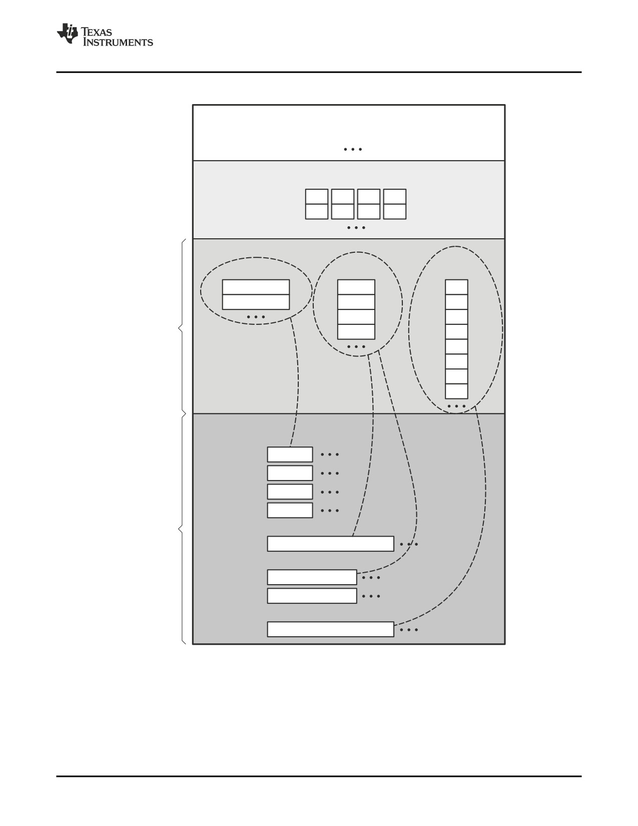
Understanding Memory Widths
Figure 11-4. Data, Memory, and ROM Widths
Source file
.word
0AABBCCDDh
.word
011223344h
Object file data (assumed to be in little-endian format)
AA
BB
CC
DD
11
22
33
44
Memory widths (variable)
-memwidth 32
-memwidth 16
-memwidth 8
AABBCCDD
CCDD
DD
11223344
AABB
CC
Data after
3344
BB
phase I
1122
AA
of hex6x
44
33
22
11
Output files
-romwidth 8
-o file.b0
DD
44
-o file.b1
CC
33
-o file.b2
BB
22
-o file.b3
AA
11
Data after
phase II
-romwidth 16
of hex6x
-o file.wrd
CCDDAABB334411
22
-romwidth 8
-o file.b0
DD BB
44
22
-o file.b1
CC AA
33
11
-romwidth 8
-o file.byt
DDCCBBAA443322
11
Hex Conversion Utility Description
237
The ROMS Directive
11.3.4
Specifying Word Order for Output Words
There are two ways to split a wide word into consecutive memory locations in the same hex conversion
utility output file:
•
-order=M specifies big-endian ordering, in which the most significant part of the wide word occupies
the first of the consecutive locations.
•
-order=L specifies little-endian ordering, in which the least significant part of the wide word occupies
the first of the consecutive locations.
By default, the utility uses little-endian format. Unless your boot loader program expects big-endian format,
avoid using -order=M.
When the -order Option Applies
Notes:
• This option applies only when you use a memory width with a value of 32
(-memwidth32). Otherwise, the hex utility does not have access to the entire 32-bit word
and cannot perform the byte swapping necessary to change the endianness; -order is
ignored.
• This option does not affect the way memory words are split into output files. Think of the
files as a set: the set contains a least significant file and a most significant file, but there
is no ordering over the set. When you list filenames for a set of files, you always list the
least significant first, regardless of the -order option.
11.4
The ROMS Directive
The ROMS directive specifies the physical memory configuration of your system as a list of address-range
parameters.
Each address range produces one set of files containing the hex conversion utility output data that
corresponds to that address range. Each file can be used to program one single ROM device.
The ROMS directive is similar to the MEMORY directive of the TMS320C6000 linker: both define the
memory map of the target address space. Each line entry in the ROMS directive defines a specific
address range. The general syntax is:
ROMS
{
romname :
[origin=value,] [length=value,] [romwidth=value,]
[ memwidth=value,] [fill=value]
[files={filename1, filename2, ...}]
romname :
[origin=value,] [length=value,] [romwidth=value,]
[ memwidth=value,] [fill=value]
[files={filename1, filename2, ...}]
}
ROMS
begins the directive definition.
romname
identifies a memory range. The name of the memory range can be one to eight
characters in length. The name has no significance to the program; it simply identifies
the range. (Duplicate memory range names are allowed.)
238
Hex Conversion Utility Description
The ROMS Directive
origin
specifies the starting address of a memory range. It can be entered as origin, org, or o.
The associated value must be a decimal, octal, or hexadecimal constant. If you omit
the origin value, the origin defaults to 0. The following table summarizes the notation
you can use to specify a decimal, octal, or hexadecimal constant:
Constant
Notation
Example
Hexadecimal
0x prefix or h suffix
0x77 or 077h
Octal
0 prefix
077
Decimal
No prefix or suffix
77
length
specifies the length of a memory range as the physical length of the ROM device. It
can be entered as length, len, or l. The value must be a decimal, octal, or hexadecimal
constant. If you omit the length value, it defaults to the length of the entire address
space.
romwidth
specifies the physical ROM width of the range in bits (see Section 11.3.3). Any value
you specify here overrides the -romwidth option. The value must be a decimal, octal,
or hexadecimal constant that is a power of 2 greater than or equal to 8.
memwidth
specifies the memory width of the range in bits (see Section 11.3.2). Any value you
specify here overrides the -memwidth option. The value must be a decimal, octal, or
hexadecimal constant that is a power of 2 greater than or equal to 8. When using the
memwidth parameter, you must also specify the paddr parameter for each section in
the SECTIONS directive. (See Section 11.5.)
fill
specifies a fill value to use for the range. In image mode, the hex conversion utility
uses this value to fill any holes between sections in a range. A hole is an area between
the input sections that comprises an output section that contains no actual code or
data. The fill value must be a decimal, octal, or hexadecimal constant with a width
equal to the target width. Any value you specify here overrides the -fill option. When
using fill, you must also use the -image command line option. (See Section 11.8.2.)
files
identifies the names of the output files that correspond to this range. Enclose the list of
names in curly braces and order them from least significant to most significant output
file, where the bits of the memory word are numbered from right to left. The number of
file names must equal the number of output files that the range generates. To calculate
the number of output files, see Section 11.3.3. The utility warns you if you list too many
or too few filenames.
Unless you are using the -image option, all of the parameters that define a range are optional; the
commas and equal signs are also optional. A range with no origin or length defines the entire address
space. In image mode, an origin and length are required for all ranges.
Ranges must not overlap and must be listed in order of ascending address.
11.4.1
When to Use the ROMS Directive
If you do not use a ROMS directive, the utility defines a single default range that includes the entire
address space. This is equivalent to a ROMS directive with a single range without origin or length.
Use the ROMS directive when you want to:
• Program large amounts of data into fixed-size ROMs. When you specify memory ranges
corresponding to the length of your ROMs, the utility automatically breaks the output into blocks that fit
into the ROMs.
Hex Conversion Utility Description
239
The ROMS Directive
• Restrict output to certain segments. You can also use the ROMS directive to restrict the conversion
to a certain segment or segments of the target address space. The utility does not convert the data
that falls outside of the ranges defined by the ROMS directive. Sections can span range boundaries;
the utility splits them at the boundary into multiple ranges. If a section falls completely outside any of
the ranges you define, the utility does not convert that section and issues no messages or warnings.
Thus, you can exclude sections without listing them by name with the SECTIONS directive. However, if
a section falls partially in a range and partially in unconfigured memory, the utility issues a warning and
converts only the part within the range.
• Use image mode. When you use the -image option, you must use a ROMS directive. Each range is
filled completely so that each output file in a range contains data for the whole range. Holes before,
between, or after sections are filled with the fill value from the ROMS directive, with the value specified
with the -fill option, or with the default value of 0.
11.4.2
An Example of the ROMS Directive
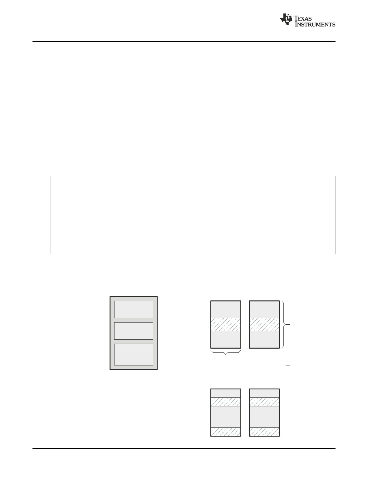
The ROMS directive in Example 11-1 shows how 16K bytes of 16-bit memory could be partitioned for two
8K-byte 8-bit EPROMs. Figure 11-5 illustrates the input and output files.
Example 11-1. A ROMS Directive Example
infile.out
-image
-memwidth 16
ROMS
}
EPROM1: org = 0x00004000, len = 0x2000, romwidth = 8
files = { rom4000.b0, rom4000.b1}
EPROM2: org = 0x00006000, len = 0x2000, romwidth = 8,
fill = 0xFF00FF00,
files = { rom6000.b0, rom6000.b1}
}
Figure 11-5. The infile.out File Partitioned Into Four Output Files
COFF file:
Output files:
infile.out
EPROM1
rom4000.b0
rom4000.b1
0x00004000
0x00004000
(org)
.text
.text
.text
0x0000487F
0x00004880
0x00005B80
0h
0h
.data
0x00005B80
0x0000633F
.data
.data
0x00006700
0x00005FFF
.table
Width = 8 bits
0x00007C7F
len = 2000h (8K)
EPROM2
rom6000.b0
rom6000.b1
0x00006000
.data
.data
0x00006340
FFh
00h
0x00006700
.table
.table
0x00007C80
FFh
00h
0x00007FFF
240
Hex Conversion Utility Description
The ROMS Directive
The map file (specified with the -map option) is advantageous when you use the ROMS directive with
multiple ranges. The map file shows each range, its parameters, names of associated output files, and a
list of contents (section names and fill values) broken down by address. Example 11-2 is a segment of the
map file resulting from the example in Example 11-1.
Example 11-2. Map File Output From Example 11-1 Showing Memory Ranges
-----------------------------------------------------
00004000..00005fff Page=0 Width=8 "EPROM1"
-----------------------------------------------------
OUTPUT FILES:
rom4000.b0
[b0..b7]
rom4000.b1
[b8..b15]
CONTENTS: 00004000..0000487f .text
00004880..00005b7f FILL = 00000000
00005b80..00005fff .data
-----------------------------------------------------
00006000..00007fff Page=0 Width=8 "EPROM2"
-----------------------------------------------------
OUTPUT FILES:
rom6000.b0
[b0..b7]
rom6000.b1
[b8..b15]
CONTENTS: 00006000..0000633f .data
00006340..000066ff FILL = ff00ff00
00006700..00007c7f .table
00007c80..00007fff FILL = ff00ff00
EPROM1 defines the address range from 0x00004000 through 0x00005FFF with the following sections:
This section ...
Has this range ...
.text
0x00004000 through 0x0000487F
.data
0x00005B80 through 0x00005FFF
The rest of the range is filled with 0h (the default fill value), converted into two output files:
• rom4000.b0 contains bits 0 through 7
• rom4000.b1 contains bits 8 through 15
EPROM2 defines the address range from 0x00006000 through 0x00007FFF with the following sections:
This section ...
Has this range ...
.data
0x00006000 through 0x0000633F
.table
0x00006700 through 0x00007C7F
The rest of the range is filled with 0xFF00FF00 (from the specified fill value). The data from this range is
converted into two output files:
• rom6000.b0 contains bits 0 through 7
• rom6000.b1 contains bits 8 through 15
Hex Conversion Utility Description
241
The SECTIONS Directive
11.5
The SECTIONS Directive
You can convert specific sections of the object file by name with the hex conversion utility SECTIONS
directive. You can also specify those sections that you want to locate in ROM at a different address than
the load address specified in the linker command file. If you:
• Use a SECTIONS directive, the utility converts only the sections that you list in the directive and
ignores all other sections in the object file.
• Do not use a SECTIONS directive, the utility converts all initialized sections that fall within the
configured memory. For the TMS320C6000 these sections are .text, .const, and .cinit.
Uninitialized sections are never converted, whether or not you specify them in a SECTIONS directive.
Sections Generated by the C/C++ Compiler
Note: The TMS320C6000 C/C++ compiler automatically generates these sections:
• Initialized sections: .text, .const, .cinit, and .switch
• Uninitialized sections: .bss, .stack, and .sysmem
Use the SECTIONS directive in a command file. (See Section 11.2.2.) The general syntax for the
SECTIONS directive is:
SECTIONS
{
sname[:] [paddr=value]
sname[:] [paddr=boot]
sname[:] [boot]
}
SECTIONS
begins the directive definition.
sname
identifies a section in the input file. If you specify a section that does not exist, the
utility issues a warning and ignores the name.
paddr=value
specifies the physical ROM address at which this section should be located. This value
overrides the section load address given by the linker. This value must be a decimal,
octal, or hexadecimal constant. It can also be the word boot (to indicate a boot table
section for use with a boot loader). If your file contains multiple sections, and if one
section uses a paddr parameter, then all sections must use a paddr parameter.
boot
configures a section for loading by a boot loader. This is equivalent to using
paddr=boot. Boot sections have a physical address determined by the location of the
boot table. The origin of the boot table is specified with the -bootorg option.
For more similarity with the linker's SECTIONS directive, you can use colons after the section names (in
place of the equal sign on the boot keyboard). For example, the following statements are equivalent:
SECTIONS { .text: .data: boot }
SECTIONS { .text: .data = boot }
In the example below, the object file contains six initialized sections: .text, .data, .const, .vectors, .coeff,
and .tables. Suppose you want only .text and .data to be converted. Use a SECTIONS directive to specify
this:
SECTIONS { .text: .data: }
To configure both of these sections for boot loading, add the boot keyword:
SECTIONS { .text = boot .data = boot }
242
Hex Conversion Utility Description
Excluding a Specified Section
Using the -boot Option and the SECTIONS Directive
Note: When you use the SECTIONS directive with the boot table (-boot) option, the -boot option is
ignored. You must explicitly specify any boot sections in the SECTIONS directive. For more
information about -boot and other command line options associated with boot tables, see
Section 11.2.
11.6
Excluding a Specified Section
The -exclude section_name option can be used to inform the hex utility to ignore the specified section. If a
SECTIONS directive is used, it overrides the -exclude option.
For example, if a SECTIONS directive containing the section name mysect is used and an -exclude
mysect is specified, the SECTIONS directive takes precedence and mysect is not excluded.
The -exclude option has a limited wildcard capability. The * character can be placed at the beginning or
end of the name specifier to indicate a suffix or prefix, respectively. For example, -exclude sect*
disqualifies all sections that begin with the characters sect.
If you specify the -exclude option on the command line with the * wildcard, enter quotes around the
section name and wildcard. For example, -exclude"sect*". Using quotes prevents the * form being
interpreted by the hex conversion utility. If -exclude is in a command file, then the quotes should not be
specified.
Hex Conversion Utility Description
243
Assigning Output Filenames
11.7
Assigning Output Filenames
When the hex conversion utility translates your object file into a data format, it partitions the data into one
or more output files. When multiple files are formed by splitting memory words into ROM words, filenames
are always assigned in order from least to most significant, where bits in the memory words are numbered
from right to left. This is true, regardless of target or endian ordering.
The hex conversion utility follows this sequence when assigning output filenames:
1.
It looks for the ROMS directive. If a file is associated with a range in the ROMS directive and you
have included a list of files (files = {. . .}) on that range, the utility takes the filename from the list.
For example, assume that the target data is 32-bit words being converted to four files, each eight bits
wide. To name the output files using the ROMS directive, you could specify:
ROMS
{
RANGE1: romwidth=8, files={ xyz.b0 xyz.b1 xyz.b2 xyz.b3 }
}
The utility creates the output files by writing the least significant bits to xyz.b0 and the most significant
bits to xyz.b3.
2.
It looks for the -o options. You can specify names for the output files by using the -o option. If no
filenames are listed in the ROMS directive and you use -o options, the utility takes the filename from
the list of -o options. The following line has the same effect as the example above using the ROMS
directive:
-o xyz.b0 -o xyz.b1 -o xyz.b2 -o xyz.b3
If both the ROMS directive and -o options are used together, the ROMS directive overrides the -o
options.
3.
It assigns a default filename. If you specify no filenames or fewer names than output files, the utility
assigns a default filename. A default filename consists of the base name from the input file plus a 2- to
3-character extension. The extension has three parts:
a. A format character, based on the output format (see Section 11.11):
a
for ASCII-Hex
i
for Intel
m for Motorola-S
t
for TI-Tagged
x
for Tektronix
b. The range number in the ROMS directive. Ranges are numbered starting with 0. If there is no
ROMS directive, or only one range, the utility omits this character.
c. The file number in the set of files for the range, starting with 0 for the least significant file.
For example, assume a.out is for a 32-bit target processor and you are creating Intel format output.
With no output filenames specified, the utility produces four output files named a.i0, a.i1, a.i2, a.i3.
If you include the following ROMS directive when you invoke the hex conversion utility, you would have
eight output files:
ROMS
{
range1: o = 0x00001000 l = 0x1000
range2: o = 0x00002000 l = 0x1000
}
These output files ...
Contain data in these locations ...
a.i00, a.i01, a.i02, a.i03
0x00001000 through 0x00001FFF
a.i10, a.i11, a.i12, a.i13
0x00002000 through 0x00002FFF
244
Hex Conversion Utility Description
Image Mode and the -fill Option
11.8
Image Mode and the -fill Option
This section points out the advantages of operating in image mode and describes how to produce output
files with a precise, continuous image of a target memory range.
11.8.1
Generating a Memory Image
With the -image option, the utility generates a memory image by completely filling all of the mapped
ranges specified in the ROMS directive.
An object file consists of blocks of memory (sections) with assigned memory locations. Typically, all
sections are not adjacent: there are holes between sections in the address space for which there is no
data. When such a file is converted without the use of image mode, the hex conversion utility bridges
these holes by using the address records in the output file to skip ahead to the start of the next section. In
other words, there may be discontinuities in the output file addresses. Some EPROM programmers do not
support address discontinuities.
In image mode, there are no discontinuities. Each output file contains a continuous stream of data that
corresponds exactly to an address range in target memory. Any holes before, between, or after sections
are filled with a fill value that you supply.
An output file converted by using image mode still has address records, because many of the
hexadecimal formats require an address on each line. However, in image mode, these addresses are
always contiguous.
Defining the Ranges of Target Memory
Note: If you use image mode, you must also use a ROMS directive. In image mode, each output
file corresponds directly to a range of target memory. You must define the ranges. If you do
not supply the ranges of target memory, the utility tries to build a memory image of the entire
target processor address space. This is potentially a huge amount of output data. To prevent
this situation, the utility requires you to explicitly restrict the address space with the ROMS
directive.
11.8.2
Specifying a Fill Value
The -fill option specifies a value for filling the holes between sections. The fill value must be specified as
an integer constant following the -fill option. The width of the constant is assumed to be that of a word on
the target processor. For example, specifying -fill 0FFFFh. The constant value is not sign extended.
The hex conversion utility uses a default fill value of 0 if you do not specify a value with the fill option. The
-fill option is valid only when you use -image; otherwise, it is ignored.
11.8.3
Steps to Follow in Using Image Mode
Step 1:
Define the ranges of target memory with a ROMS directive. See Section 11.4.
Step 2:
Invoke the hex conversion utility with the -image option. You can optionally use the -zero
option to reset the address origin to 0 for each output file. If you do not specify a fill value
with the ROMS directive and you want a value other than the default of 0, use the -fill option.
Hex Conversion Utility Description
245
Building a Table for an On-Chip Boot Loader
11.9
Building a Table for an On-Chip Boot Loader
On the C621x, C671x, and C64x devices, a ROM boot process is supported where the EDMA copies 1K
bytes from the beginning of CE1 (EMIFB CE1 on C64x) to address 0, using default ROM timings. After the
transfer, the CPU begins executing from address 0. In this mode a second level boot load typically occurs,
due to the limited amount of memory copied at boot.
The hex conversion utility supports the second level boot loader by automatically building the boot table.
11.9.1
Description of the Boot Table
The input for a boot loader is the boot table. The boot table contains records that instruct the boot loader
to copy blocks of data contained in the table to specified destination addresses. The hex conversion utility
automatically builds the boot table for the boot loader. Using the utility, you specify the sections you want
the boot loader to initialize through the boot table, the table location, and the name of the section
containing the boot loader and where it should be located. The hex conversion utility builds a complete
image of the table and converts it into hexadecimal in the output files. Then, you can burn the table into
ROM.
11.9.2
The Boot Table Format
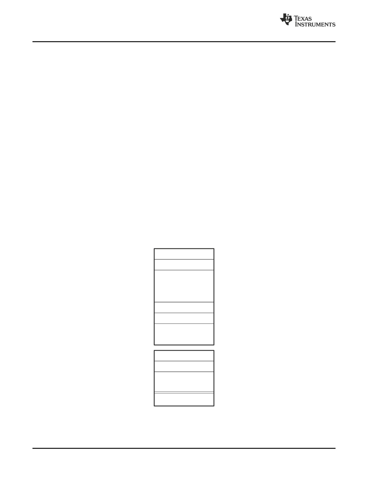
The boot table format is simple. There is a header record containing a 4 byte field that indicates where the
boot loader should branch after it has completed coping data. After the header, each section that is to be
included in the boot table will have the following:
1.
4 byte field containing the size of the section
2.
4 byte field containing the destination address for the copy
3. The actual data to be copied
Multiple sections can be entered; a termination block containing a 4 byte field of zeros follows the last
section.
Section 1 Size
Section 1 Dest
Section 1 Data
Section 2 Size
Section 2 Dest
Section 2 Data
Section N Size
Section N Dest
Section N Data
0x00000000
246
Hex Conversion Utility Description
Building a Table for an On-Chip Boot Loader
11.9.3
How to Build the Boot Table
Table 11-2 summarizes the hex conversion utility options available for the boot loader.
Table 11-2. Boot-Loader Options
Option
Description
-boot
Convert all sections into bootable form (use instead of a SECTIONS directive).
-bootorg value
Specify the source address of the boot loader table.
-bootsection sectname value
Specify the section name sectname containing the boot loader routine. The value
argument tells the hex utility where to place the boot loader routine.
-e value
Specify the entry point at which to begin execution after boot loading. The value can be
an address or a global symbol.
11.9.3.1
Building the Boot Table
To build the boot table, follow these steps:
Step
1:
Link the file. Each block of the boot table data corresponds to an initialized section in the
object file. Uninitialized sections are not converted by the hex conversion utility (see
Section 11.5). You must link into your application a boot loader routine that will read the boot
table and perform the copy operations. It should be linked to its eventual run-time address.
When you select a section for placement in a boot-loader table, the hex conversion utility
places the section's load address in the destination address field for the block in the boot
table. The section content is then treated as raw data for that block. The hex conversion
utility does not use the section run address. When linking, you need not worry about the
ROM address or the construction of the boot table-- the hex conversion utility handles this.
Step
2:
Identify the bootable sections. You can use the -boot option to tell the hex conversion
utility to configure all sections for boot loading. Or, you can use a SECTIONS directive to
select specific sections to be configured (see Section 11.5). If you use a SECTIONS
directive, the -boot option is ignored.
Step
3:
Set the ROM address of the boot table. Use the -bootorg option to set the source address
of the complete table. For example, if you are using the C6711 and booting from memory
location 0x90000400, specify -bootorg 0x90000400. The address field for the boot table in
the hex conversion utility output file will then start at 0x90000400.
If you do not use the -bootorg option at all, the utility places the table at the origin of the first
memory range in a ROMS directive. If you do not use a ROMS directive, the table will start at
the first section load address.
Step
4:
Set boot-loader-specific options. Set entry point. If -e is not used to set the entry point,
then it will default to the entry point indicated in the object file.
Step
5:
Describe the boot routine. If the boot option is used, then you should use the -bootsection
option to indicate to the hex utility which section contains the boot routine. This option will
prevent the boot routine from being in the boot table. The -bootsection option also indicates
to the hex utility where the routine should be placed in ROM. For the C621x, C671x, and
C64x devices, this address would typically be the beginning of CE1 (EMIFB CE1 on C64x).
This option is ignored if -boot is not used.
When the SECTIONS directive is used to explicitly identify which sections should exits in the
boot table, use the PADDR section option to indicate where the boot routine section will exist.
Step
6:
Describe your system memory configuration. See Section 11.3 and Section 11.4.
Hex Conversion Utility Description
247
Building a Table for an On-Chip Boot Loader
11.9.3.2
Leaving Room for the Boot Table
The complete boot table is similar to a single section containing all of the header records and data for the
boot loader. The address of this section is the boot table origin. As part of the normal conversion process,
the hex conversion utility converts the boot table to hexadecimal format and maps it into the output files
like any other section.
Be sure to leave room in your system memory for the boot table, especially when you are using the
ROMS directive. The boot table cannot overlap other nonboot sections or unconfigured memory. Usually,
this is not a problem; typically, a portion of memory in your system is reserved for the boot table. Simply
configure this memory as one or more ranges in the ROMS directive, and use the -bootorg option to
specify the starting address.
11.9.3.3
Setting the Entry Point for the Boot Table
After the boot routine finishes copying data, it branches to the entry point defined the object file. By using
the -e option with the hex conversion utility, you can set the entry point to a different address.
For example, if you want your program to start running at address 0x0123 after loading, specify
-e=0x0123 on the command line or in a command file. You can determine the -e address by looking at the
map file that the linker generates.
Valid Entry Points
Note: The value can be a constant, or it can be a symbol that is externally defined (for example,
with a .global) in the assembly source.
11.9.4
Using the C6000 Boot Loader
This subsection explains how to use the hex conversion utility with the boot loader for C6000 devices
through sample hex utility command files. Example 11-3 uses the SECTIONS directive to specify exactly
which sections will be placed in the boot table.
Example 11-3. Sample Command File for Booting From a C6000 EPROM
abc.out
/* input file
*/
-a
/* ascii format
*/
-image
/* create complete ROM image */
-zero
/* reset address origin to 0 */
-memwidth 8
/* 8-bit memory
*/
-map abchex.map
/* create a hex map file
*/
-bootorg 0x90000400
/* external memory boot
*/
ROMS
{
FLASH: org=0x90000000, len=0x20000, romwidth=8, files={abc.hex}
}
SECTIONS
{
.boot_load:
PADDR=0x90000000
.text:
BOOT
.cinit:
BOOT
.const:
BOOT
}
Example 11-4 does not explicitly name the boot sections with the SECTIONS directive. Instead, it uses the
-boot option to indicate that all initialized sections should be placed in the boot table. It also uses the
-bootsection option to distinguish the section containing the boot routine.
248
Hex Conversion Utility Description
Controlling the ROM Device Address
Example 11-4. Alternative Sample Command File for Booting From a C6x EPROM
abc.out
/* input file
*/
-a
/* ascii format
*/
-image
/* create complete Rom image */
-zero
/* reset address origin to 0 */
-memwidth 8
/* 8-bit memory
*/
-map abchex.map
/* create a hex map file
*/
-boot
/* create boot table
*/
-bootorg 0x90000400
/* external memory boot
*/
-bootsection .boot_load 0x90000000
/* give boot section & addr
*/
ROMS
{
FLASH: org=0x90000000, len=0x20000, romwidth=8, files={abc.hex}
}
11.10
Controlling the ROM Device Address
The hex conversion utility output address field corresponds to the ROM device address. The EPROM
programmer burns the data into the location specified by the hex conversion utility output file address field.
The hex conversion utility offers some mechanisms to control the starting address in ROM of each
section. However, many EPROM programmers offer direct control of the location in ROM in which the
data is burned.
Depending on whether or not you are using the boot loader, the hex conversion utility output file
controlling mechanisms are different.
Non-boot loader mode. The address field of the hex conversion utility output file is controlled by the
following mechanisms listed from low to high priority:
1. The linker command file. By default, the address field of the hex conversion utility output file is the
load address (as given in the linker command file).
2. The paddr parameter of the SECTIONS directive. When the paddr parameter is specified for a
section, the hex conversion utility bypasses the section load address and places the section in the
address specified by paddr.
3. The -zero option. When you use the -zero option, the utility resets the address origin to 0 for each
output file. Since each file starts at 0 and counts upward, any address records represent offsets from
the beginning of the file (the address within the ROM) rather than actual target addresses of the data.
You must use the -zero option in conjunction with the -image option to force the starting address in
each output file to be zero. If you specify the -zero option without the -image option, the utility issues a
warning and ignores the -zero option.
Boot-Loader Mode. When the boot loader is used, the hex conversion utility places the different sections
that are in the boot table into consecutive memory locations. Each section becomes a boot table block
whose destination address is equal to the linker-assigned section load address.
In a boot table, the address field of the hex conversion utility output file is not related to the section load
addresses assigned by the linker. The address fields of the boot table are simply offsets to the beginning
of the table. The section load addresses assigned by the linker will be encoded into the boot table along
with the size of the section and the data contained within the section. These addresses will be used to
store the data into memory during the boot load process.
The beginning of the boot table defaults to the linked load address of the first bootable section in the input
file, unless you use one of the following mechanisms, listed here from low to high priority. Higher priority
mechanisms override the values set by low priority options in an overlapping range.
1. The ROM origin specified in the ROMS directive. The hex conversion utility places the boot table at
the origin of the first memory range in a ROMS directive.
2. The -bootorg option. The hex conversion utility places the boot table at the address specified by the
-bootorg option if you select boot loading from memory.
Hex Conversion Utility Description
249
Description of the Object Formats
11.11
Description of the Object Formats
The hex conversion utility has options that identify each format. Table 11-3 specifies the format options.
They are described in the following sections.
• You need to use only one of these options on the command line. If you use more than one option, the
last one you list overrides the others.
• The default format is Tektronix (-x option).
Table 11-3. Options for Specifying Hex Conversion Formats
Option
Format
Address Bits
Default Width
-a
ASCII-Hex
16
8
-i
Intel
32
8
-m
Motorola-S
32
8
-t
TI-Tagged
16
16
--ti_txt
TI_TXT
8
8
-x
Tektronix
32
8
Address bits determine how many bits of the address information the format supports. Formats with
16-bit addresses support addresses up to 64K only. The utility truncates target addresses to fit in the
number of available bits.
The default width determines the default output width of the format. You can change the default width by
using the -romwidth option or by using the romwidth parameter in the ROMS directive. You cannot change
the default width of the TI-Tagged format, which supports a 16-bit width only.
11.11.1
ASCII-Hex Object Format (-a Option)
The ASCII-Hex object format supports 32-bit addresses. The format consists of a byte stream with bytes
separated by spaces. Figure 11-6 illustrates the ASCII-Hex format.
Figure 11-6. ASCII-Hex Object Format
Nonprintable
Nonprintable
Address
end code
start code
^B $AXXXXXXXX,
XX XX XX XX XX XX XX XX XX XX. . .^C
Data byte
The file begins with an ASCII STX character (ctrl-B, 02h) and ends with an ASCII ETX character (ctrl-C,
03h). Address records are indicated with $AXXXXXXX, in which XXXXXXXX is a 8-digit (16-bit)
hexadecimal address. The address records are present only in the following situations:
• When discontinuities occur
• When the byte stream does not begin at address 0
You can avoid all discontinuities and any address records by using the -image and -zero options. This
creates output that is simply a list of byte values.
250
Hex Conversion Utility Description
Description of the Object Formats
11.11.2
Intel MCS-86 Object Format (-i Option)
The Intel object format supports 16-bit addresses and 32-bit extended addresses. Intel format consists of
a 9-character (4-field) prefix (which defines the start of record, byte count, load address, and record type),
the data, and a 2-character checksum suffix.
The 9-character prefix represents three record types:
Record Type
Description
00
Data record
01
End-of-file record
04
Extended linear address record
Record type00, the data record, begins with a colon ( : ) and is followed by the byte count, the address of
the first data byte, the record type (00), and the checksum. The address is the least significant 16 bits of a
32-bit address; this value is concatenated with the value from the most recent 04 (extended linear
address) record to create a full 32-bit address. The checksum is the 2s complement (in binary form) of the
preceding bytes in the record, including byte count, address, and data bytes.
Record type 01, the end-of-file record, also begins with a colon ( : ), followed by the byte count, the
address, the record type (01), and the checksum.
Record type 04, the extended linear address record, specifies the upper 16 address bits. It begins with a
colon ( : ), followed by the byte count, a dummy address of 0h, the record type (04), the most significant
16 bits of the address, and the checksum. The subsequent address fields in the data records contain the
least significant bytes of the address.
Figure 11-7 illustrates the Intel hexadecimal object format.
Figure 11-7. Intel Hexadecimal Object Format
Start
Extended linear
character
address record
Address
Most significant 16 bits
:2000000000000100020003000400050006000700080009000A000B000C000D000E000F0068
:2000200010001100120013001400150016001700180019001A001B001C001D001E001F0048
Data
:2000400000000100020003000400050006000700080009000A000B000C000D000E000F0028
records
:2000600010001100120013001400150016001700180019001A001B001C001D001E001F0008
:00000001FF
Checksum
Byte
Record
End-of-file
count type
record
Hex Conversion Utility Description
251
Description of the Object Formats
11.11.3
Motorola Exorciser Object Format (-m Option)
The Motorola-S format supports 32-bit addresses. It consists of a start-of-file (header) record, data
records, and an end-of-file (termination) record. Each record consists of five fields: record type, byte
count, address, data, and checksum. The three record types are:
Record Type
Description
S0
Header record
S3
Code/data record
S7
Termination record
The byte count is the character pair count in the record, excluding the type and byte count itself.
The checksum is the least significant byte of the 1s complement of the sum of the values represented by
the pairs of characters making up the byte count, address, and the code/data fields.
Figure 11-8 illustrates the Motorola-S object format.
Figure 11-8. Motorola-S Format
Record
Address
Checksum
type
S00600004844521B
Header record
S322000000000000000000000000000000000000000000000000000000000000000000DD
Data records
S31A0001FFEB000000000000000000000000000000000000000000FA
S70500000000FA
Termination
record
Checksum
Byte count
Address for S3 records
252
Hex Conversion Utility Description