TMS320C6000 Assembly Language Tools v 6.1. User's Guide - page 5
The MEMORY Directive
The general syntax for the MEMORY directive is:
MEMORY
{
name 1
[(attr)] : origin = constant, length = constant [, fill = constant]
name n [(attr)] : origin = constant, length = constant [, fill = constant]
}
name
names a memory range. A memory name can be one to 64 characters; valid characters
include A-Z, a-z, $, ., and _. The names have no special significance to the linker; they
simply identify memory ranges. Memory range names are internal to the linker and are not
retained in the output file or in the symbol table. All memory ranges must have unique
names and must not overlap.
attr
specifies one to four attributes associated with the named range. Attributes are optional;
when used, they must be enclosed in parentheses. Attributes restrict the allocation of
output sections into certain memory ranges. If you do not use any attributes, you can
allocate any output section into any range with no restrictions. Any memory for which no
attributes are specified (including all memory in the default model) has all four attributes.
Valid attributes are:
R specifies that the memory can be read.
W specifies that the memory can be written to.
X specifies that the memory can contain executable code.
I
specifies that the memory can be initialized.
origin
specifies the starting address of a memory range; enter as origin, org, or o. The value,
specified in bytes, is a 32-bit constant and can be decimal, octal, or hexadecimal.
length
specifies the length of a memory range; enter as length, len, or l. The value, specified in
bytes, is a 32-bit constant and can be decimal, octal, or hexadecimal.
fill
specifies a fill character for the memory range; enter as fill or f. Fills are optional. The value
is a integer constant and can be decimal, octal, or hexadecimal. The fill value is used to fill
areas of the memory range that are not allocated to a section.
Filling Memory Ranges
Note: If you specify fill values for large memory ranges, your output file will be very large because
filling a memory range (even with 0s) causes raw data to be generated for all unallocated
blocks of memory in the range.
The following example specifies a memory range with the R and W attributes and a fill constant of
0FFFFFFFFh:
MEMORY
{
RFILE (RW) : o = 0x00000020, l = 0x00001000, f = 0xFFFFFFFF
}
You normally use the MEMORY directive in conjunction with the SECTIONS directive to control allocation
of output sections. After you use MEMORY to specify the target system's memory model, you can use
SECTIONS to allocate output sections into specific named memory ranges or into memory that has
specific attributes. For example, you could allocate the .text and .data sections into the area named
FAST_MEM and allocate the .bss section into the area named SLOW_MEM.
Linker Description
169
The SECTIONS Directive
7.8
The SECTIONS Directive
The SECTIONS directive controls your sections in the following ways:
• Describes how input sections are combined into output sections
• Defines output sections in the executable program
• Specifies where output sections are placed in memory (in relation to each other and to the entire
memory space)
• Permits renaming of output sections
For more information, see Section 2.3, Section 2.4, and Section 2.2.4. Subsections allow you to
manipulate sections with greater precision.
If you do not specify a SECTIONS directive, the linker uses a default algorithm for combining and
allocating the sections. Section 7.12, describes this algorithm in detail.
7.8.1
SECTIONS Directive Syntax
The SECTIONS directive is specified in a command file by the word SECTIONS (uppercase), followed by
a list of output section specifications enclosed in braces.
The general syntax for the SECTIONS directive is:
SECTIONS
{
name : [property [, property] [, property] . . . ]
name : [property [, property] [, property] . . . ]
name : [property [, property] [, property] . . . ]
}
Each section specification, beginning with name, defines an output section. (An output section is a section
in the output file.) A section name can be a subsection specification. (See Section 7.8.4 for information on
multi-level subsections.) After the section name is a list of properties that define the section's contents and
how the section is allocated. The properties can be separated by optional commas. Possible properties for
a section are as follows:
• Load allocation defines where in memory the section is to be loaded.
Syntax:
load = allocation
or
allocation
or
> allocation
• Run allocation defines where in memory the section is to be run.
Syntax:
run = allocation
or
run > allocation
• Input sections defines the input sections (object files) that constitute the output section.
Syntax:
{ input_sections }
• Section type defines flags for special section types.
Syntax:
type = COPY
or
type = DSECT
or
170
Linker Description
The SECTIONS Directive
type = NOLOAD
See Section 7.11.
• Fill value defines the value used to fill uninitialized holes.
Syntax:
fill = value
or
name : [properties =
value]
See Section 7.14.
Example 7-4 shows a SECTIONS directive in a sample link command file.
Example 7-4. The SECTIONS Directive
/**************************************************/
/* Sample command file with SECTIONS directive
*/
/**************************************************/
file1.obj
file2.obj
/* Input files
*/
--output_file=prog.out
/* Options
*/
SECTIONS
{
.text:
load = EXT_MEM, run = 0x00000800
.const:
load = FAST_MEM
.bss:
load = SLOW_MEM
.vectors:
load = 0x00000000
{
t1.obj(.intvec1)
t2.obj(.intvec2)
endvec = .;
}
.data:alpha: align = 16
.data:beta: align = 16
}
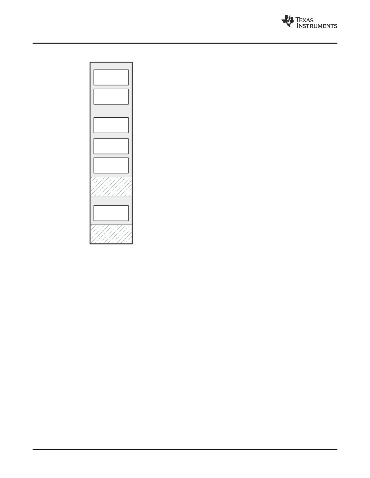
Figure 7-2 shows the six output sections defined by the SECTIONS directive in Example 7-4 (.vectors,
.text, .const, .bss, .data:alpha, and .data:beta) and shows how these sections are allocated in memory.
Linker Description
171
The SECTIONS Directive
Figure 7-2. Section Allocation Defined by Example 7-4
0x00000000
FAST_MEM
- Bound at 0x00000000
The
.vectors
section is composed of the .intvec1
.vectors
section from t1.obj and the .intvec2 section from
t2.obj.
- Allocated in FAST_MEM
The
.const
section combines the .const sections
.const
from file1.obj and file2.obj.
0x00001000
SLOW_MEM
- Allocated in SLOW_MEM
The
.bss
section combines the .bss sections from
.bss
file1.obj and file2.obj.
- Aligned on 16-byte
The
.data:alpha
subsection combines the .data:al-
.data:alpha
boundary
pha subsections from file1.obj and file2.obj. The
.data:beta
subsection combines the .data:beta
subsections from file1.obj and file2.obj. The linker
- Aligned on 16-byte
.data:beta
places the subsections anywhere there is space for
boundary
them (in SLOW_MEM in this illustration) and aligns
each on a 16-byte boundary.
0x00001800
- Empty range of memory
as defined in above
0x10000000
EXT_MEM
The
.text
section combines the .text sections from
- Allocated in EXT_MEM
file1.obj and file2.obj. The linker combines all sec-
.text
tions named .text into this section. The application
must relocate the section to run at 0x00000800.
0x10001000
- Empty range of memory
as defined in above
0xFFFFFFFF
7.8.2
Allocation
The linker assigns each output section two locations in target memory: the location where the section will
be loaded and the location where it will be run. Usually, these are the same, and you can think of each
section as having only a single address. The process of locating the output section in the target's memory
and assigning its address(es) is called allocation. For more information about using separate load and run
allocation, see Section 7.9.
If you do not tell the linker how a section is to be allocated, it uses a default algorithm to allocate the
section. Generally, the linker puts sections wherever they fit into configured memory. You can override this
default allocation for a section by defining it within a SECTIONS directive and providing instructions on
how to allocate it.
You control allocation by specifying one or more allocation parameters. Each parameter consists of a
keyword, an optional equal sign or greater-than sign, and a value optionally enclosed in parentheses. If
load and run allocation are separate, all parameters following the keyword LOAD apply to load allocation,
and those following the keyword RUN apply to run allocation. The allocation parameters are:
Binding
allocates a section at a specific address.
.text: load
=
0x1000
Named memory allocates the section into a range defined in the MEMORY directive with the specified
name (like SLOW_MEM) or attributes.
.text: load > SLOW_MEM
Alignment
uses the align or palign keyword to specify that the section must start on an address
boundary.
.text: align = 0x100
172
Linker Description
The SECTIONS Directive
Blocking
uses the block keyword to specify that the section must fit between two address
boundaries: if the section is too big, it starts on an address boundary.
.text: block(0x100)
For the load (usually the only) allocation, you can simply use a greater-than sign and omit the load
keyword:
text: > SLOW_MEM
.text: {...} > SLOW_MEM
.text: > 0x4000
If more than one parameter is used, you can string them together as follows:
.text: > SLOW_MEM align 16
Or if you prefer, use parentheses for readability:
.text: load = (SLOW_MEM align(16))
You can also use an input section specification to identify the sections from input files that are combined
to form an output section. See Section 7.8.3.
7.8.2.1
Binding
You can supply a specific starting address for an output section by following the section name with an
address:
.text: 0x00001000
This example specifies that the .text section must begin at location 0x1000. The binding address must be
a 32-bit constant.
Output sections can be bound anywhere in configured memory (assuming there is enough space), but
they cannot overlap. If there is not enough space to bind a section to a specified address, the linker issues
an error message.
Binding is Incompatible With Alignment and Named Memory
Note: You cannot bind a section to an address if you use alignment or named memory. If you try to
do this, the linker issues an error message.
7.8.2.2
Named Memory
You can allocate a section into a memory range that is defined by the MEMORY directive (see
Section 7.7). This example names ranges and links sections into them:
MEMORY
{
SLOW_MEM (RIX)
: origin = 0x00000000, length = 0x00001000
FAST_MEM (RWIX) : origin = 0x30000000, length = 0x00000300
}
SECTIONS
{
.text
:
> SLOW_MEM
.data
:
> FAST_MEM ALIGN(128)
.bss
:
> FAST_MEM
}
In this example, the linker places .text into the area called SLOW_MEM. The .data and .bss output
sections are allocated into FAST_MEM. You can align a section within a named memory range; the .data
section is aligned on a 128-byte boundary within the FAST_MEM range.
Linker Description
173
The SECTIONS Directive
Similarly, you can link a section into an area of memory that has particular attributes. To do this, specify a
set of attributes (enclosed in parentheses) instead of a memory name. Using the same MEMORY directive
declaration, you can specify:
SECTIONS
{
.text: >
(X)
/* .text --> executable memory
*/
.data: >
(RI)
/* .data --> read or init memory
*/
.bss : >
(RW)
/* .bss --> read or write memory
*/
}
In this example, the .text output section can be linked into either the SLOW_MEM or FAST_MEM area
because both areas have the X attribute. The .data section can also go into either SLOW_MEM or
FAST_MEM because both areas have the R and I attributes. The .bss output section, however, must go
into the FAST_MEM area because only FAST_MEM is declared with the W attribute.
You cannot control where in a named memory range a section is allocated, although the linker uses lower
memory addresses first and avoids fragmentation when possible. In the preceding examples, assuming no
conflicting assignments exist, the .text section starts at address 0. If a section must start on a specific
address, use binding instead of named memory.
7.8.2.3
Controlling Allocation Using The HIGH Location Specifier
The linker allocates output sections from low to high addresses within a designated memory range by
default. Alternatively, you can cause the linker to allocate a section from high to low addresses within a
memory range by using the HIGH location specifier in the SECTION directive declaration.
For example, given this MEMORY directive:
MEMORY
{
RAM
: origin = 0x0200, length = 0x0800
FLASH
: origin = 0x1100, length = 0xEEE0
VECTORS
: origin = 0xFFE0, length = 0x001E
RESET
: origin = 0xFFFE, length = 0x0002
}
and an accompanying SECTIONS directive:
SECTIONS
{
.bss
: {} > RAM
.sysmem
: {} > RAM
.stack
: {} > RAM (HIGH)
}
The HIGH specifier used on the .stack section allocation causes the linker to attempt to allocate .stack into
the higher addresses within the RAM memory range. The .bss and .sysmem sections are allocated into
the lower addresses within RAM. Example 7-5 illustrates a portion of a map file that shows where the
given sections are allocated within RAM for a typical program.
Example 7-5. Linker Allocation With the HIGH Specifier
.bss
0
00000200
00000270
UNINITIALIZED
00000200
0000011a
rtsxxx.lib
: defs.obj (.bss)
0000031a
00000088
: trgdrv.obj (.bss)
000003a2
00000078
: lowlev.obj (.bss)
0000041a
00000046
: exit.obj (.bss)
00000460
00000008
: memory.obj (.bss)
00000468
00000004
: _lock.obj (.bss)
0000046c
00000002
: fopen.obj (.bss)
0000046e
00000002
hello.obj (.bss)
.sysmem
0
00000470
00000120
UNINITIALIZED
00000470
00000004
rtsxxx .lib : memory.obj (.sysmem)
.stack
0
000008c0
00000140
UNINITIALIZED
000008c0
00000002
rtsxxx .lib : boot.obj (.stack)
174
Linker Description
The SECTIONS Directive
As shown in Example 7-5 , the .bss and .sysmem sections are allocated at the lower addresses of RAM
(0x0200 - 0x0590) and the .stack section is allocated at address 0x08c0, even though lower addresses
are available.
Without using the HIGH specifier, the linker allocation would have resulted in the code shown in Example
7-6
The HIGH specifier is ignored if it is used with specific address binding or automatic section splitting (>>
operator).
Example 7-6. Linker Allocation Without HIGH Specifier
.bss
0
00000200
00000270
UNINITIALIZED
00000200
0000011a
rtsxxx.lib
: defs.obj (.bss)
0000031a
00000088
: trgdrv.obj (.bss)
000003a2
00000078
: lowlev.obj (.bss)
0000041a
00000046
: exit.obj (.bss)
00000460
00000008
: memory.obj (.bss)
00000468
00000004
: _lock.obj (.bss)
0000046c
00000002
: fopen.obj (.bss)
0000046e
00000002
hello.obj (.bss)
.stack
0
00000470
00000140
UNINITIALIZED
00000470
00000002
rtsxxx.lib
: boot.obj (.stack)
.sysmem
0
000005b0
00000120
UNINITIALIZED
000005b0
00000004
rtsxxx.lib
: memory.obj (.sysmem)
7.8.2.4
Alignment and Blocking
You can tell the linker to place an output section at an address that falls on an n-byte boundary, where n
is a power of 2, by using the align keyword. For example, the following code allocates .text so that it falls
on a 32-byte boundary:
.text: load = align(32)
You can specify the same alignment with the palign keyword. In addition, palign ensures the section's size
is a multiple of its placement alignment restrictions, padding the section size up to such a boundary, as
needed.
Blocking is a weaker form of alignment that allocates a section anywhere within a block of size n. The
specified block size must be a power of 2. For example, the following code allocates .bss so that the entire
section is contained in a single 128-byte page or begins on that boundary.:
bss: load = block(0x0080)
You can use alignment or blocking alone or in conjunction with a memory area, but alignment and
blocking cannot be used together.
7.8.3
Specifying Input Sections
An input section specification identifies the sections from input files that are combined to form an output
section. In general, the linker combines input sections by concatenating them in the order in which they
are specified. However, if alignment or blocking is specified for an input section, all of the input sections
within the output section are ordered as follows:
• All aligned sections, from largest to smallest
• All blocked sections, from largest to smallest
• All other sections, from largest to smallest
The size of an output section is the sum of the sizes of the input sections that it comprises.
Example 7-7 shows the most common type of section specification; note that no input sections are listed.
Linker Description
175
The SECTIONS Directive
Example 7-7. The Most Common Method of Specifying Section Contents
SECTIONS
{
.text:
.data:
.bss:
}
In Example 7-7, the linker takes all the .text sections from the input files and combines them into the .text
output section. The linker concatenates the .text input sections in the order that it encounters them in the
input files. The linker performs similar operations with the .data and .bss sections. You can use this type of
specification for any output section.
You can explicitly specify the input sections that form an output section. Each input section is identified by
its filename and section name:
SECTIONS
{
.text :
/* Build .text output section
*/
{
f1.obj(.text)
/* Link .text section from f1.obj
*/
f2.obj(sec1)
/* Link sec1 section from f2.obj
*/
f3.obj
/* Link ALL sections from f3.obj
*/
f4.obj(.text,sec2) /* Link .text and sec2 from f4.obj
*/
}
}
It is not necessary for input sections to have the same name as each other or as the output section they
become part of. If a file is listed with no sections,all of its sections are included in the output section. If any
additional input sections have the same name as an output section but are not explicitly specified by the
SECTIONS directive, they are automatically linked in at the end of the output section. For example, if the
linker found more .text sections in the preceding example and these .text sections were not specified
anywhere in the SECTIONS directive, the linker would concatenate these extra sections after f4.obj(sec2).
The specifications in Example 7-7 are actually a shorthand method for the following:
SECTIONS
{
.text: { *(.text) }
.data: { *(.data) }
.bss:
{ *(.bss)
}
}
The specification *(.text) means the unallocated .text sections from all the input files. This format is useful
when:
• You want the output section to contain all input sections that have a specified name, but the output
section name is different from the input sections' name.
• You want the linker to allocate the input sections before it processes additional input sections or
commands within the braces.
The following example illustrates the two purposes above:
SECTIONS
{
.text
:
{
abc.obj(xqt)
*(.text)
}
.data
:
{
*(.data)
fil.obj(table)
}
}
176
Linker Description
The SECTIONS Directive
In this example, the .text output section contains a named section xqt from file abc.obj, which is followed
by all the .text input sections. The .data section contains all the .data input sections, followed by a named
section table from the file fil.obj. This method includes all the unallocated sections. For example, if one of
the .text input sections was already included in another output section when the linker encountered
*(.text), the linker could not include that first .text input section in the second output section.
7.8.4
Using Multi-Level Subsections
Originally, subsections were identified with the base section name and a subsection name separated by a
colon. For example, A:B names a subsection of the base section A. In certain places in a link command
file specifying a base name, such as A, selects the section A as well as any subsections of A, such as A:B
or A:C.
This concept has been extended to include multiple levels of subsection naming. The original constraints
are still true, but a name such as A:B can be used to specify a (sub)section of that name as well as any
(multi-level) subsections beginning with that name, such as A:B:C, A:B:OTHER, etc. All the subsections of
A:B are also subsections of A. A and A:B are supersections of A:B:C. Among a group of supersections of
a subsection, the nearest supersection is the supersection with the longest name. Thus, among {A, A:B}
the nearest supersection of A:B:C:D is A:B.
With multiple levels of subsections, the constraints are the following:
1. When specifying input sections within a file (or library unit) the section name selects an input section
of the same name and any subsections of that name.
2. Input sections that are not explicitly allocated are allocated in an existing output section of the same
name or in the nearest existing supersection of such an output section. An exception to this rule is that
during a partial link (specified by the --relocatable linker option) a subsection is allocated only to an
existing output section of the same name.
3. If no such output section described in 2) is defined, the input section is put in a newly created output
section with the same name as the base name of the input section
Consider linking input sections with the following names:
europe:north:norway
europe:central:france
europe:south:spain
europe:north:sweden
europe:central:germany
europe:south:italy
europe:north:finland
europe:central:denmark
europe:south:malta
europe:north:iceland
This SECTIONS specification allocates the input sections as indicated in the comments:
SECTIONS {
nordic:
{*(europe:north)
*(europe:central:denmark)} /* the nordic countries */
central: {*(europe:central)}
/* france, germany
*/
therest: {*(europe)}
/* spain, italy, malta
*/
}
This SECTIONS specification allocates the input sections as indicated in the comments:
SECTIONS {
islands: {*(europe:south:malta)
*(europe:north:iceland)}
/* malta, iceland
*/
europe:north:finland : {}
/* finland
*/
europe:north
: {}
/* norway, sweden
*/
europe:central
: {}
/* germany, denmark */
europe:central:france: {}
/* france
*/
/* (italy, spain) go into a linker-generated output section "europe" */
}
Linker Description
177
The SECTIONS Directive
Upward Compatibility of Multi-Level Subsections
Note: Existing linker commands that use the existing single-level subsection features and which do
not contain section names containing multiple colon characters continue to behave as
before. However, if section names in a link command file or in the input sections supplied to
the linker contain multiple colon characters, some change in behavior could be possible. You
should carefully consider the impact of the new rules for multiple levels to see if it affects a
particular system link.
7.8.5
Allocation Using Multiple Memory Ranges
The linker allows you to specify an explicit list of memory ranges into which an output section can be
allocated. Consider the following example:
MEMORY
{
P_MEM1 : origin = 0x02000, length = 0x01000
P_MEM2 : origin = 0x04000, length = 0x01000
P_MEM3 : origin = 0x06000, length = 0x01000
P_MEM4 : origin = 0x08000, length = 0x01000
}
SECTIONS
{
.text
: { } > P_MEM1 | P_MEM2 | P_MEM4
}
The | operator is used to specify the multiple memory ranges. The .text output section is allocated as a
whole into the first memory range in which it fits. The memory ranges are accessed in the order specified.
In this example, the linker first tries to allocate the section in P_MEM1. If that attempt fails, the linker tries
to place the section into P_MEM2, and so on. If the output section is not successfully allocated in any of
the named memory ranges, the linker issues an error message.
With this type of SECTIONS directive specification, the linker can seamlessly handle an output section
that grows beyond the available space of the memory range in which it is originally allocated. Instead of
modifying the link command file, you can let the linker move the section into one of the other areas.
7.8.6
Automatic Splitting of Output Sections Among Non-Contiguous Memory Ranges
The linker can split output sections among multiple memory ranges to achieve an efficient allocation. Use
the >> operator to indicate that an output section can be split, if necessary, into the specified memory
ranges. For example:
MEMORY
{
P_MEM1 : origin = 0x2000, length = 0x1000
P_MEM2 : origin = 0x4000, length = 0x1000
P_MEM3 : origin = 0x6000, length = 0x1000
P_MEM4 : origin = 0x8000, length = 0x1000
}
SECTIONS
{
.text: { *(.text) } >> P_MEM1 | P_MEM2 | P_MEM3 | P_MEM4
}
In this example, the >> operator indicates that the .text output section can be split among any of the listed
memory areas. If the .text section grows beyond the available memory in P_MEM1, it is split on an input
section boundary, and the remainder of the output section is allocated to P_MEM2 | P_MEM3 | P_MEM4.
The | operator is used to specify the list of multiple memory ranges.
You can also use the >> operator to indicate that an output section can be split within a single memory
range. This functionality is useful when several output sections must be allocated into the same memory
range, but the restrictions of one output section cause the memory range to be partitioned. Consider the
following example:
MEMORY
178
Linker Description
The SECTIONS Directive
{
RAM : origin = 0x1000, length = 0x8000
}
SECTIONS
{
.special: { f1.obj(.text) } = 0x4000
.text: { *(.text) } >> RAM
}
The .special output section is allocated near the middle of the RAM memory range. This leaves two
unused areas in RAM: from 0x1000 to 0x4000, and from the end of f1.obj(.text) to 0x8000. The
specification for the .text section allows the linker to split the .text section around the .special section and
use the available space in RAM on either side of .special.
The >> operator can also be used to split an output section among all memory ranges that match a
specified attribute combination. For example:
MEMORY
{
P_MEM1 (RWX) : origin = 0x1000, length = 0x2000
P_MEM2 (RWI) : origin = 0x4000, length = 0x1000
}
SECTIONS
{
.text: { *(.text) } >>
(RW)
}
The linker attempts to allocate all or part of the output section into any memory range whose attributes
match the attributes specified in the SECTIONS directive.
This SECTIONS directive has the same effect as:
SECTIONS
{
.text: { *(.text) } >> P_MEM1
| P_MEM2}
}
Certain sections should not be split:
• Certain sections created by the compiler, including
- The .cinit section, which contains the autoinitialization table for C/C++ programs
- The .pinit section, which contains the list of global constructors for C++ programs
- The .bss section, which defines global variables
• An output section with an input section specification that includes an expression to be evaluated. The
expression may define a symbol that is used in the program to manage the output section at run time.
• An output section that has a START(), END(), OR SIZE() operator applied to it. These operators
provide information about a section's load or run address, and size. Splitting the section may
compromise the integrity of the operation.
• The run allocation of a UNION. (Splitting the load allocation of a UNION is allowed.)
If you use the >> operator on any of these sections, the linker issues a warning and ignores the operator.
7.8.7
Allocating an Archive Member to an Output Section
The ability to specify an archive member of a library archive for allocation into a specific output section
can be specified inside angle brackets after a library name. Any object files separated by commas or
spaces from the specified archive file are legal within the angle brackets. The syntax for allocating
archived library members specifically inside of a SECTIONS directive is as follows:
[--library=] library name <member1[,] member2[,] ...> [(input sections)]
Linker Description
179
Specifying a Section's Run-Time Address
Example 7-8 specifies that the text sections of boot.obj, exit.obj, and strcpy.obj from the run-time-support
library should be placed in section .boot. The remainder of the .text sections from the run-time-support
library are to be placed in section .rts. Finally, the remainder of all other .text sections are to be placed in
section .text.
Example 7-8. Archive Members to Output Sections
SECTIONS
{
boot
>
BOOT1
{
--library=rtsXX.lib<boot.obj> (.text)
--library=rtsXX.lib<exit.obj strcpy.obj> (.text)
}
.rts
>
BOOT2
{
--library=rtsXX.lib (.text)
}
.text
>
RAM
{
* (.text)
}
}
The --library option (which normally implies a library path search be made for the named file following the
option) listed before each library in Example 7-8 is optional when listing specific archive members inside <
>. Using < > implies that you are referring to a library.
To collect a set of the input sections from a library in one place, use the --library option within the
SECTIONS directive. For example, the following collects all the .text sections from rts62.lib into the .rtstest
section:
SECTIONS
{
.rtstest { ---library=rts62.lib(.text) } > RAM
}
SECTIONS Directive Effect on --priority
Note: Specifying a library in a SECTIONS directive causes that library to be entered in the list of
libraries that the linker searches to resolve references. If you use the --priority option, the first
library specified in the command file will be searched first.
7.9
Specifying a Section's Run-Time Address
At times, you may want to load code into one area of memory and run it in another. For example, you may
have performance-critical code in slow external memory. The code must be loaded into slow external
memory, but it would run faster in fast external memory.
The linker provides a simple way to accomplish this. You can use the SECTIONS directive to direct the
linker to allocate a section twice: once to set its load address and again to set its run address. For
example:
.fir: load = SLOW_MEM, run = FAST_MEM
Use the load keyword for the load address and the run keyword for the run address.
See Section 2.5 for an overview on run-time relocation.
180
Linker Description
Specifying a Section's Run-Time Address
7.9.1
Specifying Load and Run Addresses
The load address determines where a loader places the raw data for the section. Any references to the
section (such as labels in it) refer to its run address. The application must copy the section from its load
address to its run address; this does not happen automatically when you specify a separate run address.
If you provide only one allocation (either load or run) for a section, the section is allocated only once and
loads and runs at the same address. If you provide both allocations, the section is allocated as if it were
two sections of the same size. This means that both allocations occupy space in the memory map and
cannot overlay each other or other sections. (The UNION directive provides a way to overlay sections; see
Section 7.10.1.)
If either the load or run address has additional parameters, such as alignment or blocking, list them after
the appropriate keyword. Everything related to allocation after the keyword load affects the load address
until the keyword run is seen, after which, everything affects the run address. The load and run allocations
are completely independent, so any qualification of one (such as alignment) has no effect on the other.
You can also specify run first, then load. Use parentheses to improve readability.
The examples below specify load and run addresses:
.data: load = SLOW_MEM, align = 32, run = FAST_MEM
(align applies only to load)
.data: load = (SLOW_MEM align 32), run = FAST_MEM
(identical to previous example)
.data: run
= FAST_MEM, align 32,
load = align 16
(align 32 in FAST_MEM for run; align 16 anywhere for load)
7.9.2
Uninitialized Sections
Uninitialized sections (such as .bss) are not loaded, so their only significant address is the run address.
The linker allocates uninitialized sections only once: if you specify both run and load addresses, the linker
warns you and ignores the load address. Otherwise, if you specify only one address, the linker treats it as
a run address, regardless of whether you call it load or run. This example specifies load and run
addresses for an uninitialized section:
.bss: load = 0x1000, run = FAST_MEM
A warning is issued, load is ignored, and space is allocated in FAST_MEM. All of the following examples
have the same effect. The .bss section is allocated in FAST_MEM.
.bss: load = FAST_MEM
.bss: run = FAST_MEM
.bss: > FAST_MEM
7.9.3
Referring to the Load Address by Using the .label Directive
Normally, any reference to a symbol in a section refers to its run-time address. However, it may be
necessary at run time to refer to a load-time address. Specifically, the code that copies a section from its
load address to its run address must have access to the load address. The .label directive defines a
special symbol that refers to the section's load address. Thus, whereas normal symbols are relocated with
respect to the run address, .label symbols are relocated with respect to the load address. See Create a
Load-Time Address Label for more information on the .label directive.
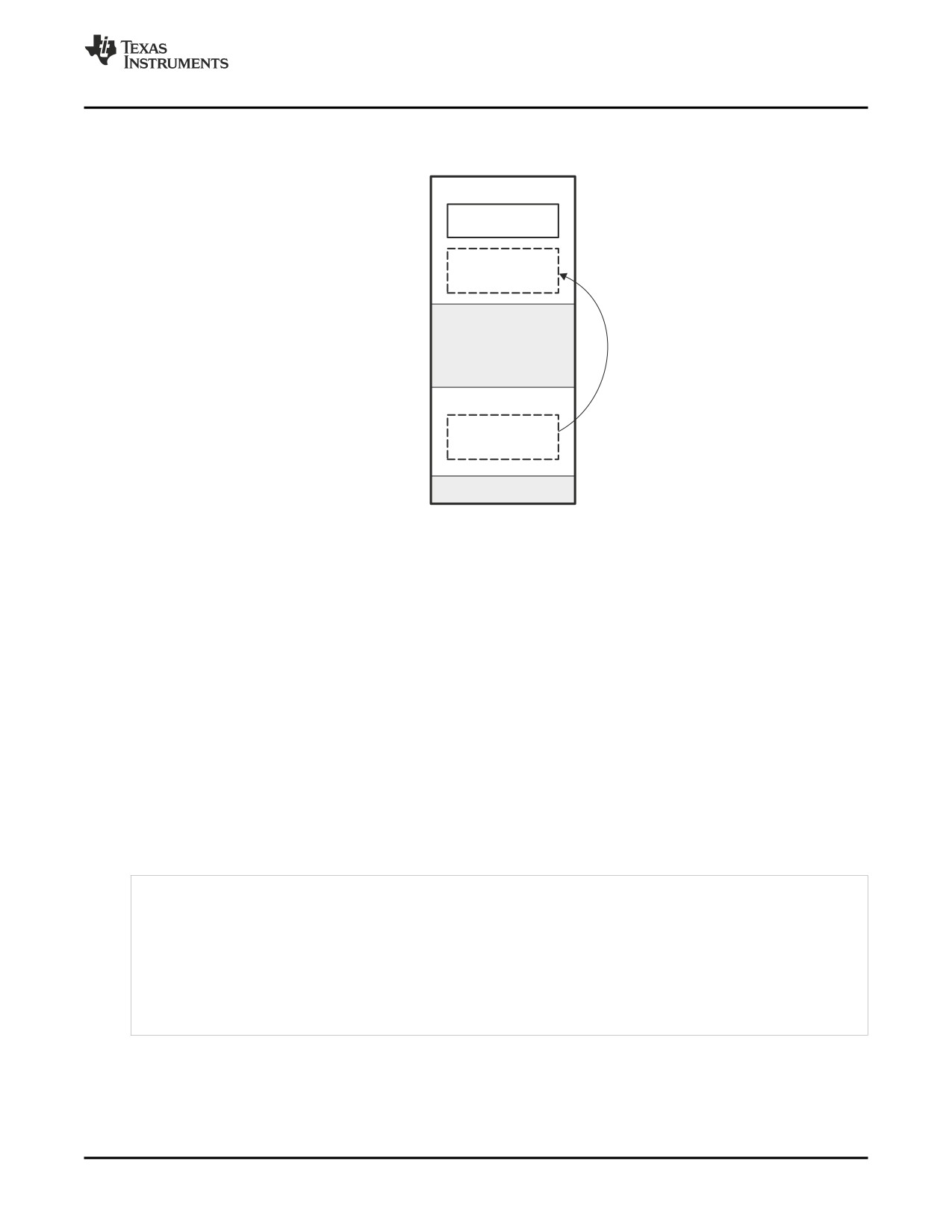
Example 7-9 and Example 7-10 show the use of the .label directive to copy a section from its load address
in SLOW_MEM to its run address in FAST_MEM. Figure 7-3 illustrates the run-time execution of Example
7-9.
Linker Description
181
Specifying a Section's Run-Time Address
Example 7-9. Copying Section Assembly Language File
.sect ".fir"
.align 4
.label fir_src
fir
; insert code here
.label fir_end
.text
MVKL
fir_src, A4
MVKH
fir_src, A4
MVKL
fir_end, A5
MVKH
fir_end, A5
MVKL
fir, A6
MVKH
fir, A6
SUB
A5, A4, A1
loop:
[!A1] B
done
LDW
*A4+ +, B3
NOP
4
; branch occurs
STW
B3, *A6+ +
SUB
A1, 4, A1
B
loop
NOP
5
; branch occurs
done:
B
fir
NOP
5
; call occurs
Example 7-10. Linker Command File for Example 7-9
/******************************************************/
/*
PARTIAL LINKER COMMAND FILE FOR FIR EXAMPLE
*/
/******************************************************/
MEMORY
{
FAST_MEM : origin = 0x00001000, length = 0x00001000
SLOW_MEM : origin = 0x10000000, length = 0x00001000
}
SECTIONS
{
.text: load = FAST_MEM
.fir: load = SLOW_MEM, run FAST_MEM
}
182
Linker Description
Using UNION and GROUP Statements
Figure 7-3. Run-Time Execution of Example 7-9
0x00000000
FAST_MEM
.text
fir (relocated
to run here)
0x00001000
0x10000000
SLOW_MEM
fir (loads here)
0x10001000
0xFFFFFFFF
7.10
Using UNION and GROUP Statements
Two SECTIONS statements allow you to conserve memory: GROUP and UNION. Unioning sections
causes the linker to allocate them to the same run address. Grouping sections causes the linker to
allocate them contiguously in memory. Section names can refer to sections, subsections, or archive library
members.
7.10.1
Overlaying Sections With the UNION Statement
For some applications, you may want to allocate more than one section to run at the same address. For
example, you may have several routines you want in fast external memory at various stages of execution.
Or you may want several data objects that are not active at the same time to share a block of memory.
The UNION statement within the SECTIONS directive provides a way to allocate several sections at the
same run-time address.
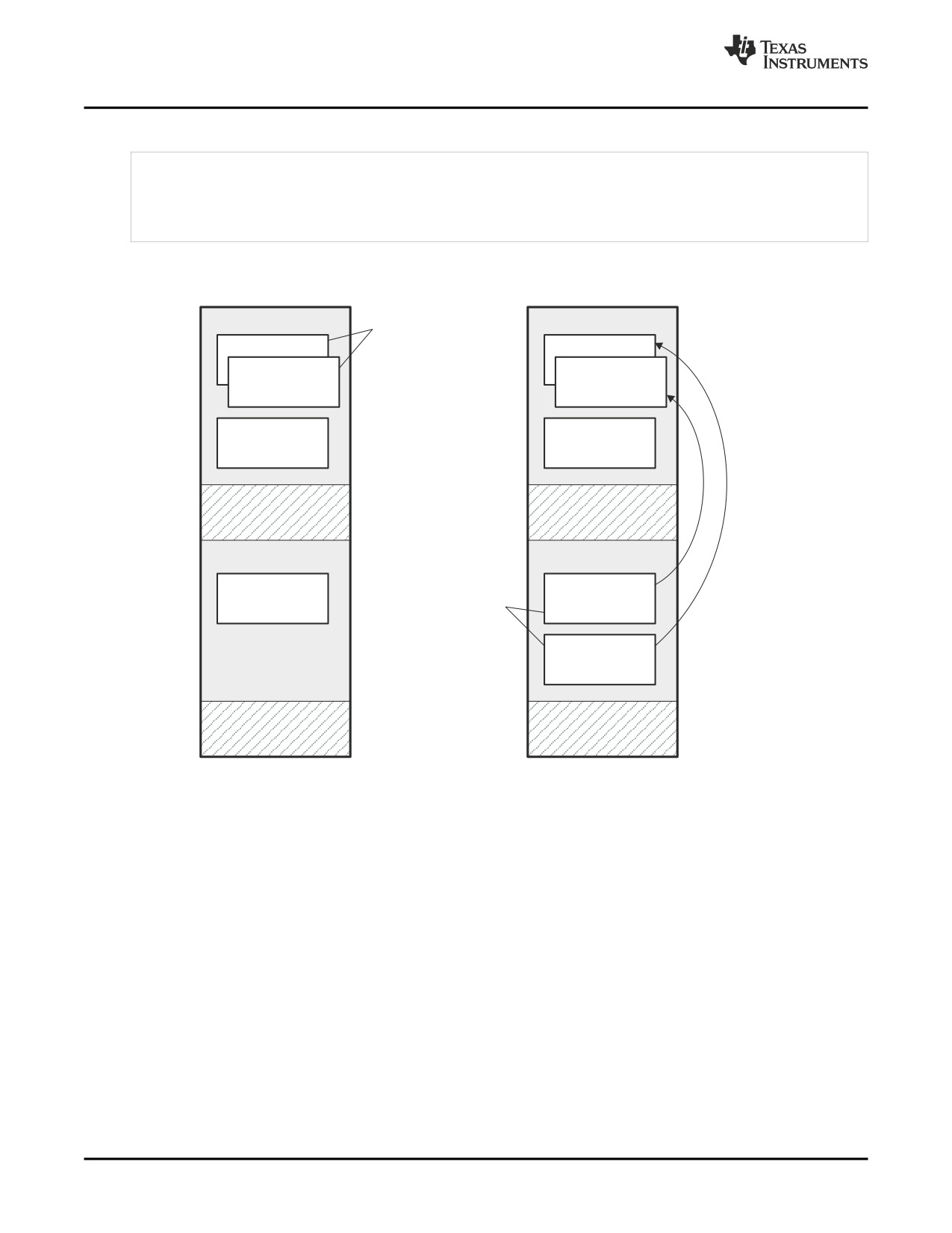
In Example 7-11, the .bss sections from file1.obj and file2.obj are allocated at the same address in
FAST_MEM. In the memory map, the union occupies as much space as its largest component. The
components of a union remain independent sections; they are simply allocated together as a unit.
Example 7-11. The UNION Statement
SECTIONS
{
.text: load = SLOW_MEM
UNION: run
= FAST_MEM
{
.bss:part1: { file1.obj(.bss) }
.bss:part2: { file2.obj(.bss) }
}
.bss:part3: run = FAST_MEM { globals.obj(.bss) }
}
Allocation of a section as part of a union affects only its run address. Under no circumstances can
sections be overlaid for loading. If an initialized section is a union member (an initialized section, such as
.text, has raw data), its load allocation must be separately specified. See Example 7-12.
Linker Description
183
Using UNION and GROUP Statements
Example 7-12. Separate Load Addresses for UNION Sections
UNION run = FAST_MEM
{
.text:part1: load = SLOW_MEM, { file1.obj(.text) }
.text:part2: load = SLOW_MEM, { file2.obj(.text) }
}
Figure 7-4. Memory Allocation Shown in Example 7-11 and Example 7-12
FAST_MEM
Sections can run
FAST_MEM
as a union. This
Copies at
.bss:part2
is run-time alloca-
.text 2 (run)
run time
.bss:part1
tion only.
.text 1 (run)
.bss:part3
.bss:part3
SLOW_MEM
SLOW_MEM
.text
.text 1 (load)
Sections cannot
load as a union
.text 2 (load)
Since the .text sections contain data, they cannot load as a union, although they can be run as a union.
Therefore, each requires its own load address. If you fail to provide a load allocation for an initialized
section within a UNION, the linker issues a warning and allocates load space anywhere it can in
configured memory.
Uninitialized sections are not loaded and do not require load addresses.
The UNION statement applies only to allocation of run addresses, so it is meaningless to specify a load
address for the union itself. For purposes of allocation, the union is treated as an uninitialized section: any
one allocation specified is considered a run address, and if both run and load addresses are specified, the
linker issues a warning and ignores the load address.
184
Linker Description
Using UNION and GROUP Statements
7.10.2
Grouping Output Sections Together
The SECTIONS directive's GROUP option forces several output sections to be allocated contiguously. For
example, assume that a section named term_rec contains a termination record for a table in the .data
section. You can force the linker to allocate .data and term_rec together:
Example 7-13. Allocate Sections Together
SECTIONS
{
.text
/* Normal output section
*/
.bss
/* Normal output section
*/
GROUP 0x00001000 : /* Specify a group of sections
*/
{
.data
/* First section in the group
*/
term_rec
/* Allocated immediately after .data */
}
}
You can use binding, alignment, or named memory to allocate a GROUP in the same manner as a single
output section. In the preceding example, the GROUP is bound to address 0x1000. This means that .data
is allocated at 0x1000, and term_rec follows it in memory.
You Cannot Specify Addresses for Sections Within a GROUP
Note: When you use the GROUP option, binding, alignment, or allocation into named memory can
be specified for the group only. You cannot use binding, named memory, or alignment for
sections within a group.
7.10.3
Nesting UNIONs and GROUPs
The linker allows arbitrary nesting of GROUP and UNION statements with the SECTIONS directive. By
nesting GROUP and UNION statements, you can express hierarchical overlays and groupings of sections.
Example 7-14 shows how two overlays can be grouped together.
Example 7-14. Nesting GROUP and UNION Statements
SECTIONS
{
GROUP 0x1000 : run = FAST_MEM
{
UNION:
{
mysect1: load = SLOW_MEM
mysect2: load = SLOW_MEM
}
UNION:
{
mysect3: load = SLOW_MEM
mysect4: load = SLOW_MEM
}
}
}
For this example, the linker performs the following allocations:
• The four sections (mysect1, mysect2, mysect3, mysect4) are assigned unique, non-overlapping load
addresses in the SLOW_MEM memory region. This assignment is determined by the particular load
allocations given for each section.
• Sections mysect1 and mysect2 are assigned the same run address in FAST_MEM.
• Sections mysect3 and mysect4 are assigned the same run address in FAST_MEM.
Linker Description
185
Using UNION and GROUP Statements
• The run addresses of mysect1/mysect2 and mysect3/mysect4 are allocated contiguously, as directed
by the GROUP statement (subject to alignment and blocking restrictions).
To refer to groups and unions, linker diagnostic messages use the notation:
GROUP_n UNION_n
In this notation, n is a sequential number (beginning at 1) that represents the lexical ordering of the group
or union in the linker control file, without regard to nesting. Groups and unions each have their own
counter.
7.10.4
Checking the Consistency of Allocators
The linker checks the consistency of load and run allocations specified for unions, groups, and sections.
The following rules are used:
• Run allocations are only allowed for top-level sections, groups, or unions (sections, groups, or unions
that are not nested under any other groups or unions). The linker uses the run address of the top-level
structure to compute the run addresses of the components within groups and unions.
• The linker does not accept a load allocation for UNIONs.
• The linker does not accept a load allocation for uninitialized sections.
• In most cases, you must provide a load allocation for an initialized section. However, the linker does
not accept a load allocation for an initialized section that is located within a group that already defines
a load allocator.
• As a shortcut, you can specify a load allocation for an entire group, to determine the load allocations
for every initialized section or subgroup nested within the group. However, a load allocation is
accepted for an entire group only if all of the following conditions are true:
- The group is initialized (that is, it has at least one initialized member).
- The group is not nested inside another group that has a load allocator.
- The group does not contain a union containing initialized sections.
• If the group contains a union with initialized sections, it is necessary to specify the load allocation for
each initialized section nested within the group. Consider the following example:
SECTIONS
{
GROUP: load = SLOW_MEM, run = SLOW_MEM
{
.text1:
UNION:
{
.text2:
.text3:
}
}
}
• The load allocator given for the group does not uniquely specify the load allocation for the elements
within the union: .text2 and .text3. In this case, the linker issues a diagnostic message to request that
these load allocations be specified explicitly.
186
Linker Description
Special Section Types (DSECT, COPY, and NOLOAD)
7.10.5
Naming UNIONs and GROUPs
You can give a name to a UNION or GROUP by entering the name in parentheses after the declaration.
For example:
GROUP(BSS_SYSMEM_STACK_GROUP)
{
.bss
:{}
.sysmem :{}
.stack
:{}
} load=D_MEM, run=D_MEM
The name you defined is used in diagnostics for easy identification of the problem LCF area. For example:
warning: LOAD placement ignored for "BSS_SYSMEM_STACK_GROUP": object is uninitialized
UNION(TEXT_CINIT_UNION)
{
.const :{}load=D_MEM, table(table1)
.pinit :{}load=D_MEM, table(table1)
}run=P_MEM
warning:table(table1) operator ignored: table(table1) has already been applied to a section
in the "UNION(TEXT_CINIT_UNION)" in which ".pinit" is a descendant
7.11
Special Section Types (DSECT, COPY, and NOLOAD)
You can assign three special types to output sections: DSECT, COPY, and NOLOAD. These types affect
the way that the program is treated when it is linked and loaded. You can assign a type to a section by
placing the type after the section definition. For example:
SECTIONS
{
sec1: load = 0x00002000, type = DSECT
{f1.obj}
sec2: load = 0x00004000, type = COPY
{f2.obj}
sec3: load = 0x00006000, type = NOLOAD {f3.obj}
}
• The DSECT type creates a dummy section with the following characteristics:
- It is not included in the output section memory allocation. It takes up no memory and is not included
in the memory map listing.
- It can overlay other output sections, other DSECTs, and unconfigured memory.
- Global symbols defined in a dummy section are relocated normally. They appear in the output
module's symbol table with the same value they would have if the DSECT had actually been
loaded. These symbols can be referenced by other input sections.
- Undefined external symbols found in a DSECT cause specified archive libraries to be searched.
- The section's contents, relocation information, and line number information are not placed in the
output module.
In the preceding example, none of the sections from f1.obj are allocated, but all the symbols are
relocated as though the sections were linked at address 0x2000. The other sections can refer to any of
the global symbols in sec1.
• A COPY section is similar to a DSECT section, except that its contents and associated information are
written to the output module. The .cinit section that contains initialization tables for the TMS320C6000
C/C++ compiler has this attribute under the run-time initialization model.
• A NOLOAD section differs from a normal output section in one respect: the section's contents,
relocation information, and line number information are not placed in the output module. The linker
allocates space for the section, and it appears in the memory map listing.
Linker Description
187
Default Allocation Algorithm
7.12
Default Allocation Algorithm
The MEMORY and SECTIONS directives provide flexible methods for building, combining, and allocating
sections. However, any memory locations or sections that you choose not to specify must still be handled
by the linker. The linker uses default algorithms to build and allocate sections within the specifications you
supply.
If you do not use the MEMORY and SECTIONS directives, the linker allocates output sections as though
the definitions in Example 7-15 were specified.
Example 7-15. Default Allocation for TMS320C6000 Devices
MEMORY
{
RAM
: origin = 0x00000001, length = 0xFFFFFFFE
}
SECTIONS
{
.text
: ALIGN(32) {} > RAM
.const : ALIGN(8)
{} > RAM
.data
: ALIGN(8)
{} > RAM
.bss
: ALIGN(8)
{} > RAM
.cinit : ALIGN(4)
{} > RAM
; cflag option only
.pinit : ALIGN(4)
{} > RAM
; cflag option only
.stack : ALIGN(8)
{} > RAM
; cflag option only
.far
: ALIGN(8)
{} > RAM
; cflag option only
.sysmem: ALIGN(8)
{} > RAM
; cflag option only
.switch: ALIGN(4)
{} > RAM
; cflag option only
.cio
: ALIGN(4)
{} > RAM
; cflag option only
}
All .text input sections are concatenated to form a .text output section in the executable output file, and all
.data input sections are combined to form a .data output section.
If you use a SECTIONS directive, the linker performs no part of the default allocation. Allocation is
performed according to the rules specified by the SECTIONS directive and the general algorithm
described next in Section 7.12.1.
7.12.1
How the Allocation Algorithm Creates Output Sections
An output section can be formed in one of two ways:
Method 1
As the result of a SECTIONS directive definition
Method 2
By combining input sections with the same name into an output section that is not defined in
a SECTIONS directive
If an output section is formed as a result of a SECTIONS directive, this definition completely determines
the section's contents. (See Section 7.8 for examples of how to define an output section's content.)
If an output section is formed by combining input sections not specified by a SECTIONS directive, the
linker combines all such input sections that have the same name into an output section with that name.
For example, suppose the files f1.obj and f2.obj both contain named sections called Vectors and that the
SECTIONS directive does not define an output section for them. The linker combines the two Vectors
sections from the input files into a single output section named Vectors, allocates it into memory, and
includes it in the output file.
By default, the linker does not display a message when it creates an output section that is not defined in
the SECTIONS directive. You can use the --warn_sections linker option (see Section 7.4.33) to cause the
linker to display a message when it creates a new output section.
188
Linker Description
Assigning Symbols at Link Time
After the linker determines the composition of all output sections, it must allocate them into configured
memory. The MEMORY directive specifies which portions of memory are configured. If there is no
MEMORY directive, the linker uses the default configuration as shown in Example 7-15. (See Section 7.7
for more information on configuring memory.)
7.12.2
Reducing Memory Fragmentation
The linker's allocation algorithm attempts to minimize memory fragmentation. This allows memory to be
used more efficiently and increases the probability that your program will fit into memory. The algorithm
comprises these steps:
1. Each output section for which you have supplied a specific binding address is placed in memory at that
address.
2. Each output section that is included in a specific, named memory range or that has memory attribute
restrictions is allocated. Each output section is placed into the first available space within the named
area, considering alignment where necessary.
3. Any remaining sections are allocated in the order in which they are defined. Sections not defined in a
SECTIONS directive are allocated in the order in which they are encountered. Each output section is
placed into the first available memory space, considering alignment where necessary.
7.13
Assigning Symbols at Link Time
Linker assignment statements allow you to define external (global) symbols and assign values to them at
link time. You can use this feature to initialize a variable or pointer to an allocation-dependent value.
7.13.1
Syntax of Assignment Statements
The syntax of assignment statements in the linker is similar to that of assignment statements in the C
language:
symbol
=
expression;
assigns the value of expression to symbol
symbol
+=
expression;
adds the value of expression to symbol
symbol
-=
expression;
subtracts the value of expression from symbol
symbol
*=
expression;
multiplies symbol by expression
symbol
/=
expression;
divides symbol by expression
The symbol should be defined externally. If it is not, the linker defines a new symbol and enters it into the
symbol table. The expression must follow the rules defined in Section 7.13.3. Assignment statements must
terminate with a semicolon.
The linker processes assignment statements after it allocates all the output sections. Therefore, if an
expression contains a symbol, the address used for that symbol reflects the symbol's address in the
executable output file.
For example, suppose a program reads data from one of two tables identified by two external symbols,
Table1 and Table2. The program uses the symbol cur_tab as the address of the current table. The
cur_tab symbol must point to either Table1 or Table2. You could accomplish this in the assembly code,
but you would need to reassemble the program to change tables. Instead, you can use a linker
assignment statement to assign cur_tab at link time:
prog.obj
/* Input file
*/
cur_tab = Table1; /* Assign cur_tab to one of the tables */
Linker Description
189
Assigning Symbols at Link Time
7.13.2
Assigning the SPC to a Symbol
A special symbol, denoted by a dot (.), represents the current value of the section program counter (SPC)
during allocation. The SPC keeps track of the current location within a section. The linker's . symbol is
analogous to the assembler's $ symbol. The . symbol can be used only in assignment statements within a
SECTIONS directive because . is meaningful only during allocation and SECTIONS controls the allocation
process. (See Section 7.8.)
The . symbol refers to the current run address, not the current load address, of the section.
For example, suppose a program needs to know the address of the beginning of the .data section. By
using the .global directive (see Identify Global Symbols ), you can create an external undefined variable
called Dstart in the program. Then, assign the value of . to Dstart:
SECTIONS
{
.text:
{}
.data:
{Dstart = .;}
.bss :
{}
}
This defines Dstart to be the first linked address of the .data section. (Dstart is assigned before .data is
allocated.) The linker relocates all references to Dstart.
A special type of assignment assigns a value to the . symbol. This adjusts the SPC within an output
section and creates a hole between two input sections. Any value assigned to . to create a hole is relative
to the beginning of the section, not to the address actually represented by the . symbol. Holes and
assignments to . are described in Section 7.14.
7.13.3
Assignment Expressions
These rules apply to linker expressions:
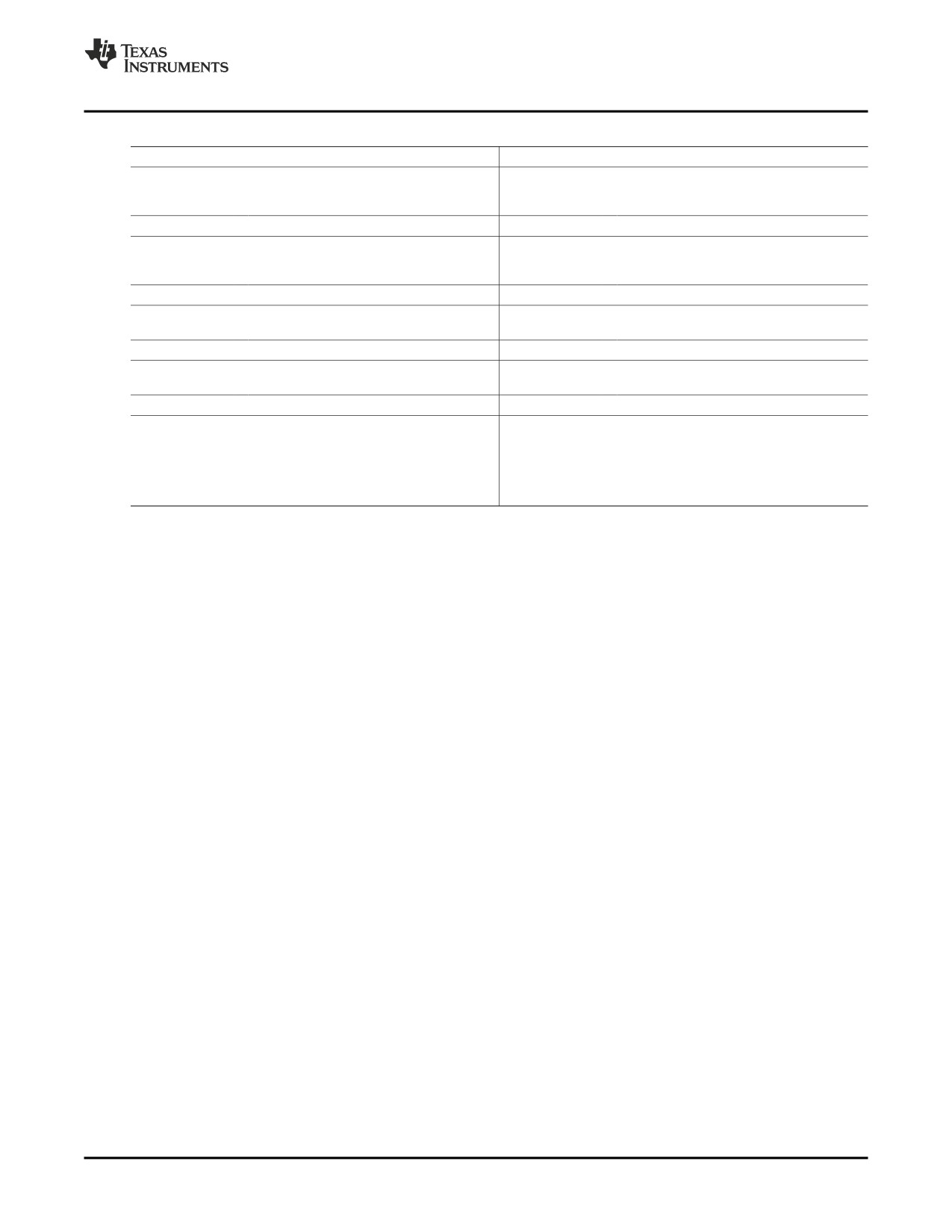
• Expressions can contain global symbols, constants, and the C language operators listed in Table 7-2.
• All numbers are treated as long (32-bit) integers.
• Constants are identified by the linker in the same way as by the assembler. That is, numbers are
recognized as decimal unless they have a suffix (H or h for hexadecimal and Q or q for octal). C
language prefixes are also recognized (0 for octal and 0x for hex). Hexadecimal constants must begin
with a digit. No binary constants are allowed.
• Symbols within an expression have only the value of the symbol's address. No type-checking is
performed.
• Linker expressions can be absolute or relocatable. If an expression contains any relocatable symbols
(and 0 or more constants or absolute symbols), it is relocatable. Otherwise, the expression is absolute.
If a symbol is assigned the value of a relocatable expression, it is relocatable; if it is assigned the value
of an absolute expression, it is absolute.
The linker supports the C language operators listed in Table 7-2 in order of precedence. Operators in the
same group have the same precedence. Besides the operators listed in Table 7-2, the linker also has an
align operator that allows a symbol to be aligned on an n-byte boundary within an output section (n is a
power of 2). For example, the following expression aligns the SPC within the current section on the next
16-byte boundary. Because the align operator is a function of the current SPC, it can be used only in the
same context as . —that is, within a SECTIONS directive.
. = align(16);
190
Linker Description
Assigning Symbols at Link Time
Table 7-2. Groups of Operators Used in Expressions (Precedence)
Group 1 (Highest Precedence)
Group 6
!
Logical NOT
&
Bitwise AND
~
Bitwise NOT
-
Negation
Group 2
Group 7
Multiplication
|
Bitwise OR
/
Division
%
Modulus
Group 3
Group 8
+
Addition
&&
Logical AND
-
Subtraction
Group 4
Group 9
>>
Arithmetic right shift
||
Logical OR
<<
Arithmetic left shift
Group 5
Group 10 (Lowest Precedence)
==
Equal to
=
Assignment
!=
Not equal to
+=
A+=B"A=A+B
>
Greater than
-=
A-=B"A=A-B
<
Less than
*=
A*=B"A=A*B
<=
Less than or equal to
/=
A/=B"A=A/B
>=
Greater than or equal to
7.13.4
Symbols Defined by the Linker
The linker automatically defines several symbols based on which sections are used in your assembly
source. A program can use these symbols at run time to determine where a section is linked. Since these
symbols are external, they appear in the linker map. Each symbol can be accessed in any assembly
language module if it is declared with a .global directive (see Identify Global Symbols ). You must have
used the corresponding section in a source module for the symbol to be created. Values are assigned to
these symbols as follows:
.text
is assigned the first address of the .text output section.
(It marks the beginning of executable code.)
etext
is assigned the first address following the .text output section.
(It marks the end of executable code.)
.data
is assigned the first address of the .data output section.
(It marks the beginning of initialized data tables.)
edata
is assigned the first address following the .data output section.
(It marks the end of initialized data tables.)
.bss
is assigned the first address of the .bss output section.
(It marks the beginning of uninitialized data.)
end
is assigned the first address following the .bss output section.
(It marks the end of uninitialized data.)
The following symbols are defined only for C/C++ support when the --ram_model or --rom_model option is
used.
__STACK_SIZE
is assigned the size of the .stack section.
__SYSMEM_SIZE
is assigned the size of the .sysmem section.
Linker Description
191
Assigning Symbols at Link Time
7.13.5
Assigning Exact Start, End, and Size Values of a Section to a Symbol
The code generation tools currently support the ability to load program code in one area of (slow) memory
and run it in another (faster) area. This is done by specifying separate load and run addresses for an
output section or group in the link command file. Then execute a sequence of instructions (the copying
code in Example 7-9) that moves the program code from its load area to its run area before it is needed.
There are several responsibilities that a programmer must take on when setting up a system with this
feature. One of these responsibilities is to determine the size and run-time address of the program code to
be moved. The current mechanisms to do this involve use of the .label directives in the copying code. A
simple example is illustrated Example 7-9.
This method of specifying the size and load address of the program code has limitations. While it works
fine for an individual input section that is contained entirely within one source file, this method becomes
more complicated if the program code is spread over several source files or if the programmer wants to
copy an entire output section from load space to run space.
Another problem with this method is that it does not account for the possibility that the section being
moved may have an associated far call trampoline section that needs to be moved with it.
7.13.6
Why the Dot Operator Does Not Always Work
The dot operator (.) is used to define symbols at link-time with a particular address inside of an output
section. It is interpreted like a PC. Whatever the current offset within the current section is, that is the
value associated with the dot. Consider an output section specification within a SECTIONS directive:
outsect:
{
s1.obj(.text)
end_of_s1
= .;
start_of_s2 = .;
s2.obj(.text)
end_of_s2 = .;
}
This statement creates three symbols:
• end_of_s1—the end address of .text in s1.obj
• start_of_s2—the start address of .text in s2.obj
• end_of_s2—the end address of .text in s2.obj
Suppose there is padding between s1.obj and s2.obj that is created as a result of alignment. Then
start_of_s2 is not really the start address of the .text section in s2.obj, but it is the address before the
padding needed to align the .text section in s2.obj. This is due to the linker's interpretation of the dot
operator as the current PC. It is also due to the fact that the dot operator is evaluated independently of the
input sections around it.
Another potential problem in the above example is that end_of_s2 may not account for any padding that
was required at the end of the output section. You cannot reliably use end_of_s2 as the end address of
the output section. One way to get around this problem is to create a dummy section immediately after the
output section in question. For example:
GROUP
{
outsect:
{
start_of_outsect = .;
}
dummy: { size_of_outsect = . - start_of_outsect; }
}
192
Linker Description
Assigning Symbols at Link Time
7.13.7
Address and Dimension Operators
Six new operators have been added to the link command file syntax:
LOAD_START( sym ) Defines sym with the load-time start address of related allocation unit
START( sym )
LOAD_END( sym )
Defines sym with the load-time end address of related allocation unit
END( sym )
LOAD_SIZE( sym )
Defines sym with the load-time size of related allocation unit
SIZE( sym )
RUN_START( sym )
Defines sym with the run-time start address of related allocation unit
RUN_END( sym )
Defines sym with the run-time end address of related allocation unit
RUN_SIZE(sym)
Defines sym with the run-time size of related allocation unit
Linker Command File Operator Equivalencies
Note: LOAD_START() and START() are equivalent, as are LOAD_END()/END() and
LOAD_SIZE()/SIZE().
The new address and dimension operators can be associated with several different kinds of allocation
units, including input items, output sections, GROUPs, and UNIONs. The following sections provide some
examples of how the operators can be used in each case.
7.13.7.1
Input Items
Consider an output section specification within a SECTIONS directive:
outsect:
{
s1.obj(.text)
end_of_s1
= .;
start_of_s2 = .;
s2.obj(.text)
end_of_s2 = .;
}
This can be rewritten using the START and END operators as follows:
outsect:
{
s1.obj(.text) { END(end_of_s1) }
s2.obj(.text) { START(start_of_s2), END(end_of_s2) }
}
The values of end_of_s1 and end_of_s2 will be the same as if you had used the dot operator in the
original example, but start_of_s2 would be defined after any necessary padding that needs to be added
between the two .text sections. Remember that the dot operator would cause start_of_s2 to be defined
before any necessary padding is inserted between the two input sections.
The syntax for using these operators in association with input sections calls for braces { } to enclose the
operator list. The operators in the list are applied to the input item that occurs immediately before the list.
7.13.7.2
Output Section
The START, END, and SIZE operators can also be associated with an output section. Here is an example:
outsect: START(start_of_outsect), SIZE(size_of_outsect)
{
<list of input items>
}
Linker Description
193
Creating and Filling Holes
In this case, the SIZE operator defines size_of_outsect to incorporate any padding that is required in the
output section to conform to any alignment requirements that are imposed.
The syntax for specifying the operators with an output section do not require braces to enclose the
operator list. The operator list is simply included as part of the allocation specification for an output
section.
7.13.7.3
GROUPs
Here is another use of the START and SIZE operators in the context of a GROUP specification:
GROUP
{
outsect1: { ... }
outsect2: { ... }
} load = ROM, run = RAM, START(group_start), SIZE(group_size);
This can be useful if the whole GROUP is to be loaded in one location and run in another. The copying
code can use group_start and group_size as parameters for where to copy from and how much is to be
copied. This makes the use of .label in the source code unnecessary.
7.13.7.4
UNIONs
The RUN_SIZE and LOAD_SIZE operators provide a mechanism to distinguish between the size of a
UNION's load space and the size of the space where its constituents are going to be copied before they
are run. Here is an example:
UNION: run = RAM, LOAD_START(union_load_addr),
LOAD_SIZE(union_ld_sz), RUN_SIZE(union_run_sz)
{
.text1: load = ROM, SIZE(text1_size) { f1.obj(.text) }
.text2: load = ROM, SIZE(text2_size) { f2.obj(.text) }
}
Here union_ld_sz is going to be equal to the sum of the sizes of all output sections placed in the union.
The union_run_sz value is equivalent to the largest output section in the union. Both of these symbols
incorporate any padding due to blocking or alignment requirements.
7.14
Creating and Filling Holes
The linker provides you with the ability to create areas within output sections that have nothing linked into
them. These areas are called holes. In special cases, uninitialized sections can also be treated as holes.
This section describes how the linker handles holes and how you can fill holes (and uninitialized sections)
with values.
7.14.1
Initialized and Uninitialized Sections
There are two rules to remember about the contents of output sections. An output section contains either:
• Raw data for the entire section
• No raw data
A section that has raw data is referred to as initialized. This means that the object file contains the actual
memory image contents of the section. When the section is loaded, this image is loaded into memory at
the section's specified starting address. The .text and .data sections always have raw data if anything was
assembled into them. Named sections defined with the .sect assembler directive also have raw data.
By default, the .bss section (see Reserve Space in the .bss Section ) and sections defined with the .usect
directive (see Reserve Uninitialized Space ) have no raw data (they are uninitialized). They occupy space
in the memory map but have no actual contents. Uninitialized sections typically reserve space in fast
external memory for variables. In the object file, an uninitialized section has a normal section header and
can have symbols defined in it; no memory image, however, is stored in the section.
194
Linker Description
Creating and Filling Holes
7.14.2
Creating Holes
You can create a hole in an initialized output section. A hole is created when you force the linker to leave
extra space between input sections within an output section. When such a hole is created, the linker must
supply raw data for the hole.
Holes can be created only within output sections. Space can exist between output sections, but such
space is not a hole. To fill the space between output sections, see Section 7.7.2.
To create a hole in an output section, you must use a special type of linker assignment statement within
an output section definition. The assignment statement modifies the SPC (denoted by .) by adding to it,
assigning a greater value to it, or aligning it on an address boundary. The operators, expressions, and
syntaxes of assignment statements are described in Section 7.13.
The following example uses assignment statements to create holes in output sections:
SECTIONS
{
outsect:
{
file1.obj(.text)
. += 0x0100
/* Create a hole with size 0x0100 */
file2.obj(.text)
. = align(16);
/* Create a hole to align the SPC */
file3.obj(.text)
}
}
The output section outsect is built as follows:
1. The .text section from file1.obj is linked in.
2. The linker creates a 256-byte hole.
3. The .text section from file2.obj is linked in after the hole.
4. The linker creates another hole by aligning the SPC on a 16-byte boundary.
5. Finally, the .text section from file3.obj is linked in.
All values assigned to the . symbol within a section refer to the relative address within the section. The
linker handles assignments to the . symbol as if the section started at address 0 (even if you have
specified a binding address). Consider the statement . = align(16) in the example. This statement
effectively aligns the file3.obj .text section to start on a 16-byte boundary within outsect. If outsect is
ultimately allocated to start on an address that is not aligned, the file3.obj .text section will not be aligned
either.
The . symbol refers to the current run address, not the current load address, of the section.
Expressions that decrement the . symbol are illegal. For example, it is invalid to use the -= operator in an
assignment to the . symbol. The most common operators used in assignments to the . symbol are += and
align.
If an output section contains all input sections of a certain type (such as .text), you can use the following
statements to create a hole at the beginning or end of the output section.
.text:
{
.+= 0x0100; }
/* Hole at the beginning */
.data:
{
*(.data)
. += 0x0100; }
/* Hole at the end
*/
Another way to create a hole in an output section is to combine an uninitialized section with an initialized
section to form a single output section. In this case, the linker treats the uninitialized section as a hole and
supplies data for it. The following example illustrates this method:
SECTIONS
{
outsect:
{
file1.obj(.text)
file1.obj(.bss)
/* This becomes a hole */
}
}
Because the .text section has raw data, all of outsect must also contain raw data. Therefore, the
uninitialized .bss section becomes a hole.
Linker Description
195
Creating and Filling Holes
Uninitialized sections become holes only when they are combined with initialized sections. If several
uninitialized sections are linked together, the resulting output section is also uninitialized.
7.14.3
Filling Holes
When a hole exists in an initialized output section, the linker must supply raw data to fill it. The linker fills
holes with a 32-bit fill value that is replicated through memory until it fills the hole. The linker determines
the fill value as follows:
1.
If the hole is formed by combining an uninitialized section with an initialized section, you can specify a
fill value for the uninitialized section. Follow the section name with an = sign and a 32-bit constant. For
example:
SECTIONS
{ outsect:
{
file1.obj(.text)
file2.obj(.bss)= 0xFF00FF00
/* Fill this hole with 0xFF00FF00 */
}
}
2.
You can also specify a fill value for all the holes in an output section by supplying the fill value after the
section definition:
SECTIONS
{ outsect:fill = 0xFF00FF00
/* Fills holes with 0xFF00FF00 */
{
. += 0x0010;
/* This creates a hole
*/
file1.obj(.text)
file1.obj(.bss)
/* This creates another hole
*/
}
}
3.
If you do not specify an initialization value for a hole, the linker fills the hole with the value specified
with the --fill_value option (see Section 7.4.10). For example, suppose the command file link.cmd
contains the following SECTIONS directive:
SECTIONS
{
.text: { .= 0x0100; }
/* Create a 100 word hole */
}
Now invoke the linker with the --fill_value option:
cl6x --run_linker --fill_value=0xFFFFFFFF link.cmd
This fills the hole with 0xFFFFFFFF.
4.
If you do not invoke the linker with the --fill_value option or otherwise specify a fill value, the linker fills
holes with 0s.
Whenever a hole is created and filled in an initialized output section, the hole is identified in the link map
along with the value the linker uses to fill it.
7.14.4
Explicit Initialization of Uninitialized Sections
You can force the linker to initialize an uninitialized section by specifying an explicit fill value for it in the
SECTIONS directive. This causes the entire section to have raw data (the fill value). For example:
SECTIONS
{
.bss: fill = 0x12341234 /* Fills .bss with 0x12341234 */
}
Filling Sections
Note: Because filling a section (even with 0s) causes raw data to be generated for the entire
section in the output file, your output file will be very large if you specify fill values for large
sections or holes.
196
Linker Description
Linker-Generated Copy Tables
7.15
Linker-Generated Copy Tables
The linker supports extensions to the link command file syntax that enable the following:
• Make it easier for you to copy objects from load-space to run-space at boot time
• Make it easier for you to manage memory overlays at run time
• Allow you to split GROUPs and output sections that have separate load and run addresses
7.15.1
A Current Boot-Loaded Application Development Process
In some embedded applications, there is a need to copy or download code and/or data from one location
to another at boot time before the application actually begins its main execution thread. For example, an
application may have its code and/or data in FLASH memory and need to copy it into on-chip memory
before the application begins execution.
One way you can develop an application like this is to create a copy table in assembly code that contains
three elements for each block of code or data that needs to be moved from FLASH into on-chip memory
at boot time:
• The load address
• The run address
• The size
The process you follow to develop such an application might look like this:
1. Build the application to produce a .map file that contains the load and run addresses of each section
that has a separate load and run placement.
2. Edit the copy table (used by the boot loader) to correct the load and run addresses as well as the size
of each block of code or data that needs to be moved at boot time.
3. Build the application again, incorporating the updated copy table.
4. Run the application.
This process puts a heavy burden on you to maintain the copy table (by hand, no less). Each time a piece
of code or data is added or removed from the application, you must repeat the process in order to keep
the contents of the copy table up to date.
7.15.2
An Alternative Approach
You can avoid some of this maintenance burden by using the LOAD_START(), RUN_START(), and
SIZE() operators that are already part of the link command file syntax . For example, instead of building
the application to generate a .map file, the link command file can be annotated:
SECTIONS
{
.flashcode: { app_tasks.obj(.text) }
load = FLASH, run = PMEM,
LOAD_START(_flash_code_ld_start),
RUN_START(_flash_code_rn_start),
SIZE(_flash_code_size)
}
In this example, the LOAD_START(), RUN_START(), and SIZE() operators instruct the linker to create
three symbols:
Symbol
Description
_flash_code_ld_start
Load address of .flashcode section
_flash_code_rn_start
Run address of .flashcode section
_flash_code_size
Size of .flashcode section
Linker Description
197
Linker-Generated Copy Tables
These symbols can then be referenced from the copy table. The actual data in the copy table will be
updated automatically each time the application is linked. This approach removes step 1 of the process
described in Section 7.15.1.
While maintenance of the copy table is reduced markedly, you must still carry the burden of keeping the
copy table contents in sync with the symbols that are defined in the link command file. Ideally, the linker
would generate the boot copy table automatically. This would avoid having to build the application twice
and free you from having to explicitly manage the contents of the boot copy table.
For more information on the LOAD_START(), RUN_START(), and SIZE() operators, see Section 7.13.7.
7.15.3
Overlay Management Example
Consider an application which contains a memory overlay that must be managed at run time. The memory
overlay is defined using a UNION in the link command file as illustrated in Example 7-16:
Example 7-16. Using a UNION for Memory Overlay
SECTIONS
{
UNION
{
GROUP
{
.task1: { task1.obj(.text) }
.task2: { task2.obj(.text) }
} load = ROM, LOAD_START(_task12_load_start), SIZE(_task12_size)
GROUP
{
.task3: { task3.obj(.text) }
.task4: { task4.obj(.text) }
} load = ROM, LOAD_START(_task34_load_start), SIZE(_task_34_size)
} run = RAM, RUN_START(_task_run_start)
}
The application must manage the contents of the memory overlay at run time. That is, whenever any
services from .task1 or .task2 are needed, the application must first ensure that .task1 and .task2 are
resident in the memory overlay. Similarly for .task3 and .task4.
To affect a copy of .task1 and .task2 from ROM to RAM at run time, the application must first gain access
to the load address of the tasks (_task12_load_start), the run address (_task_run_start), and the size
(_task12_size). Then this information is used to perform the actual code copy.
7.15.4
The table() Operator
You can use the table() operator to instruct the linker to produce a copy table. A table() operator can be
applied to an output section, a GROUP, or a UNION member. The copy table generated for a particular
table() specification can be accessed through a symbol specified by you that is provided as an argument
to the table() operator. The linker creates a symbol with this name and assigns it the address of the copy
table as the value of the symbol. The copy table can then be accessed from the application using the
linker-generated symbol.
198
Linker Description
Linker-Generated Copy Tables
Each table() specification you apply to members of a given UNION must contain a unique name. If a
table() operator is applied to a GROUP, then none of that GROUP's members may be marked with a
table() specification. The linker detects violations of these rules and reports them as warnings, ignoring
each offending use of the table() specification. The linker does not generate a copy table for erroneous
table() operator specifications.
7.15.5
Boot-Time Copy Tables
The linker supports a special copy table name, BINIT (or binit), that you can use to create a boot-time
copy table. For example, the link command file for the boot-loaded application described in Section 7.15.2
can be rewritten as follows:
SECTIONS
{
.flashcode: { app_tasks.obj(.text) }
load = FLASH, run = PMEM,
table(BINIT)
}
For this example, the linker creates a copy table that can be accessed through a special linker-generated
symbol, ___binit__, which contains the list of all object components that need to be copied from their load
location to their run location at boot-time. If a link command file does not contain any uses of table(BINIT),
then the ___binit__ symbol is given a value of -1 to indicate that a boot-time copy table does not exist for
a particular application.
You can apply the table(BINIT) specification to an output section, GROUP, or UNION member. If used in
the context of a UNION, only one member of the UNION can be designated with table(BINIT). If applied to
a GROUP, then none of that GROUP's members may be marked with table(BINIT).The linker detects
violations of these rules and reports them as warnings, ignoring each offending use of the table(BINIT)
specification.
7.15.6
Using the table() Operator to Manage Object Components
If you have several pieces of code that need to be managed together, then you can apply the same table()
operator to several different object components. In addition, if you want to manage a particular object
component in multiple ways, you can apply more than one table() operator to it. Consider the link
command file excerpt in Example 7-17:
Example 7-17. Linker Command File to Manage Object Components
SECTIONS
{
UNION
{
.first: { a1.obj(.text), b1.obj(.text), c1.obj(.text) }
load = EMEM, run = PMEM, table(BINIT), table(_first_ctbl)
.second: { a2.obj(.text), b2.obj(.text) }
load = EMEM, run = PMEM, table(_second_ctbl)
}
.extra: load = EMEM, run = PMEM, table(BINIT)
}
In this example, the output sections .first and .extra are copied from external memory (EMEM) into
program memory (PMEM) at boot time while processing the BINIT copy table. After the application has
started executing its main thread, it can then manage the contents of the overlay using the two overlay
copy tables named: _first_ctbl and _second_ctbl.
Linker Description
199
Linker-Generated Copy Tables
7.15.7
Copy Table Contents
In order to use a copy table that is generated by the linker, you must be aware of the contents of the copy
table. This information is included in a new run-time-support library header file, cpy_tbl.h, which contains a
C source representation of the copy table data structure that is automatically generated by the linker.
Example 7-18 shows the TMS320C6000 copy table header file.
Example 7-18. TMS320C6000 cpy_tbl.h File
/****************************************************************************/
/* cpy_tbl.h
*/
/*
*/
/* Copyright (c) 2003 Texas Instruments Incorporated
*/
/*
*/
/* Specification of copy table data structures which can be automatically
*/
/* generated by the linker (using the table() operator in the LCF).
*/
/*
*/
/****************************************************************************/
/****************************************************************************/
/* Copy Record Data Structure
*/
/****************************************************************************/
typedef struct copy_record
{
unsigned int load_addr;
unsigned int run_addr;
unsigned int size;
} COPY_RECORD;
/****************************************************************************/
/* Copy Table Data Structure
*/
/****************************************************************************/
typedef struct copy_table
{
unsigned short rec_size;
unsigned short num_recs;
COPY_RECORD
recs[1];
} COPY_TABLE;
/****************************************************************************/
/* Prototype for general purpose copy routine.
*/
/****************************************************************************/
extern void copy_in(COPY_TABLE *tp);
For each object component that is marked for a copy, the linker creates a COPY_RECORD object for it.
Each COPY_RECORD contains at least the following information for the object component:
• The load address
• The run address
• The size
The linker collects all COPY_RECORDs that are associated with the same copy table into a
COPY_TABLE object. The COPY_TABLE object contains the size of a given COPY_RECORD, the
number of COPY_RECORDs in the table, and the array of COPY_RECORDs in the table. For instance, in
the BINIT example in Section 7.15.5, the .first and .extra output sections will each have their own
COPY_RECORD entries in the BINIT copy table. The BINIT copy table will then look like this:
COPY_TABLE __binit__ = { 12, 2,
{ <load address of .first>,
<run address of .first>,
<size of .first> },
{ <load address of .extra>,
<run address of .extra>,
<size of .extra> } };
200
Linker Description
Linker-Generated Copy Tables
7.15.8
General Purpose Copy Routine
The cpy_tbl.h file in Example 7-18 also contains a prototype for a general-purpose copy routine, copy_in(),
which is provided as part of the run-time-support library. The copy_in() routine takes a single argument:
the address of a linker-generated copy table. The routine then processes the copy table data object and
performs the copy of each object component specified in the copy table.
The copy_in() function definition is provided in the cpy_tbl.c run-time-support source file shown in Example
7-19.
Example 7-19. Run-Time-Support cpy_tbl.c File
/****************************************************************************/
/* cpy_tbl.c
*/
/*
*/
/* Copyright (c) 2003 Texas Instruments Incorporated
*/
/*
*/
/* General purpose copy routine. Given the address of a link-generated
*/
/* COPY_TABLE data structure, effect the copy of all object components
*/
/* that are designated for copy via the corresponding LCF table() operator. */
/*
*/
/****************************************************************************/
#include <cpy_tbl.h>
#include <string.h>
/****************************************************************************/
/* COPY_IN()
*/
/****************************************************************************/
void copy_in(COPY_TABLE *tp)
{
unsigned short I;
for (I = 0; I < tp->num_recs; I++)
{
COPY_RECORD crp = tp->recs[i];
unsigned char *ld_addr = (unsigned char *)crp.load_addr;
unsigned char *rn_addr = (unsigned char *)crp.run_addr;
memcpy(rn_addr, ld_addr, crp.size);
}
}
7.15.9
Linker-Generated Copy Table Sections and Symbols
The linker creates and allocates a separate input section for each copy table that it generates. Each copy
table symbol is defined with the address value of the input section that contains the corresponding copy
table.
The linker generates a unique name for each overlay copy table input section. For example,
table(_first_ctbl) would place the copy table for the .first section into an input section called
.ovly:_first_ctbl. The linker creates a single input section, .binit, to contain the entire boot-time copy table.
The linker generates a unique name for each overlay copy table input section. For example,
table(_first_ctbl) would place the copy table for the .first section into an input section called
.ovly:_first_ctbl. The linker creates a single input section, .binit, to contain the entire boot-time copy table.
Linker Description
201
Linker-Generated Copy Tables
Example 7-20. Controlling the Placement of the Linker-Generated Copy Table Sections
SECTIONS
{
UNION
{
.first: { a1.obj(.text), b1.obj(.text), c1.obj(.text) }
load = EMEM, run = PMEM, table(BINIT), table(_first_ctbl)
.second: { a2.obj(.text), b2.obj(.text) }
load = EMEM, run = PMEM, table(_second_ctbl)
}
.extra: load = EMEM, run = PMEM, table(BINIT)
.ovly: { } > BMEM
.binit: { } > BMEM
}
For the link command file in Example 7-20, the boot-time copy table is generated into a .binit input section,
which is collected into the .binit output section, which is mapped to an address in the BMEM memory
area. The _first_ctbl is generated into the .ovly:_first_ctbl input section and the _second_ctbl is generated
into the .ovly:_second_ctbl input section. Since the base names of these input sections match the name of
the .ovly output section, the input sections are collected into the .ovly output section, which is then
mapped to an address in the BMEM memory area.
If you do not provide explicit placement instructions for the linker-generated copy table sections, they are
allocated according to the linker's default placement algorithm.
The linker does not allow other types of input sections to be combined with a copy table input section in
the same output section. The linker does not allow a copy table section that was created from a partial link
session to be used as input to a succeeding link session.
7.15.10
Splitting Object Components and Overlay Management
In previous versions of the linker, splitting sections that have separate load and run placement instructions
was not permitted. This restriction was because there was no effective mechanism for you, the developer,
to gain access to the load address or run address of each one of the pieces of the split object component.
Therefore, there was no effective way to write a copy routine that could move the split section from its load
location to its run location.
However, the linker can access both the load address and run address of every piece of a split object
component. Using the table() operator, you can tell the linker to generate this information into a copy table.
The linker gives each piece of the split object component a COPY_RECORD entry in the copy table
object.
For example, consider an application which has seven tasks. Tasks 1 through 3 are overlaid with tasks 4
through 7 (using a UNION directive). The load placement of all of the tasks is split among four different
memory areas (LMEM1, LMEM2, LMEM3, and LMEM4). The overlay is defined as part of memory area
PMEM. You must move each set of tasks into the overlay at run time before any services from the set are
used.
You can use table() operators in combination with splitting operators, >>, to create copy tables that have
all the information needed to move either group of tasks into the memory overlay as shown in Example
7-21. Example 7-22 illustrates a possible driver for such an application.
202
Linker Description
Linker-Generated Copy Tables
Example 7-21. Creating a Copy Table to Access a Split Object Component
SECTIONS
{
UNION
{
.task1to3: { *(.task1), *(.task2), *(.task3) }
load >> LMEM1 | LMEM2 | LMEM4, table(_task13_ctbl)
GROUP
{
.task4: { *(.task4) }
.task5: { *(.task5) }
.task6: { *(.task6) }
.task7: { *(.task7) }
} load >> LMEM1 | LMEM3 | LMEM4, table(_task47_ctbl)
} run = PMEM
.ovly: > LMEM4
}
Example 7-22. Split Object Component Driver
#include <cpy_tbl.h>
extern far COPY_TABLE task13_ctbl;
extern far COPY_TABLE task47_ctbl;
extern void task1(void);
extern void task7(void);
main()
{
copy_in(&task13_ctbl);
task1();
task2();
task3();
copy_in(&task47_ctbl);
task4();
task5();
task6();
task7();
}
You must declare a COPY_TABLE object as far to allow the overlay copy table section placement to be
independent from the other sections containing data objects (such as .bss).
The contents of the .task1to3 section are split in the section's load space and contiguous in its run space.
The linker-generated copy table, _task13_ctbl, contains a separate COPY_RECORD for each piece of the
split section .task1to3. When the address of _task13_ctbl is passed to copy_in(), each piece of .task1to3
is copied from its load location into the run location.
The contents of the GROUP containing tasks 4 through 7 are also split in load space. The linker performs
the GROUP split by applying the split operator to each member of the GROUP in order. The copy table for
the GROUP then contains a COPY_RECORD entry for every piece of every member of the GROUP.
These pieces are copied into the memory overlay when the _task47_ctbl is processed by copy_in().
Linker Description
203
Partial (Incremental) Linking
The split operator can be applied to an output section, GROUP, or the load placement of a UNION or
UNION member. The linker does not permit a split operator to be applied to the run placement of either a
UNION or of a UNION member. The linker detects such violations, emits a warning, and ignores the
offending split operator usage.
7.16
Partial (Incremental) Linking
An output file that has been linked can be linked again with additional modules. This is known as partial
linking or incremental linking. Partial linking allows you to partition large applications, link each part
separately, and then link all the parts together to create the final executable program.
Follow these guidelines for producing a file that you will relink:
• The intermediate files produced by the linker must have relocation information. Use the --relocatable
option when you link the file the first time. (See Section 7.4.2.2.)
• Intermediate files must have symbolic information. By default, the linker retains symbolic information in
its output. Do not use the --no_sym_table option if you plan to relink a file, because --no_sym_table
strips symbolic information from the output module. (See Section 7.4.21.)
• Intermediate linkers should be concerned only with the formation of output sections and not with
allocation. All allocation, binding, and MEMORY directives should be performed in the final linker.
• If the intermediate files have global symbols that have the same name as global symbols in other files
and you want them to be treated as static (visible only within the intermediate file), you must link the
files with the --make_static option (see Section 7.4.16).
• If you are linking C code, do not use --ram_model or --rom_model until the final linker. Every time you
invoke the linker with the --ram_model or --rom_model option, the linker attempts to create an entry
point. (See Section 7.4.23.)
The following example shows how you can use partial linking:
Step 1:
Link the file file1.com; use the --relocatable option to retain relocation information in the
output file tempout1.out.
cl6x --run_linker --relocatable --output_file=tempout1 file1.com
file1.com contains:
SECTIONS { ss1:
{ f1.obj f2.obj . . . fn.obj
}
}
Step 2:
Link the file file2.com; use the --relocatable option to retain relocation information in the
output file tempout2.out.
cl6x --run_linker --relocatable --output_file=tempout2 file2.com
file2.com contains:
SECTIONS { ss2:
{ g1.obj g2.obj . . . gn.obj
}
}
Step 3:
Link tempout1.out and tempout2.out.
cl6x
--run_linker
--map_file=final.map
--output_file=final.out tempout1.out
tempout2.out
204
Linker Description
Linking C/C++ Code
7.17
Linking C/C++ Code
The C/C++ compiler produces assembly language source code that can be assembled and linked. For
example, a C program consisting of modules prog1, prog2, etc., can be assembled and then linked to
produce an executable file called prog.out:
cl6x --run_linker --rom_model --output_file prog.out prog1.obj prog2.obj ... rts62.lib
The --rom_model option tells the linker to use special conventions that are defined by the C/C++
environment.
The archive libraries shipped by TI contain C/C++ run-time-support functions.
C, C++, and mixed C and C++ programs can use the same run-time-support library. Run-time-support
functions and variables that can be called and referenced from both C and C++ will have the same
linkage.
For more information about the TMS320C6000 C/C++ language, including the run-time environment and
run-time-support functions, see the TMS320C6000 Optimizing Compiler User's Guide
7.17.1
Run-Time Initialization
All C/C++ programs must be linked with code to initialize and execute the program, called a bootstrap
routine, also known as the boot.obj object module. The symbol _c_int00 is defined as the program entry
point and is the start of the C boot routine in boot.obj; referencing _c_int00 ensures that boot.obj is
automatically linked in from the run-time-support library. When a program begins running, it executes
boot.obj first. The boot.obj symbol contains code and data for initializing the run-time environment and
performs the following tasks:
• Sets up the system stack and configuration registers
• Processes the run-time .cinit initialization table and autoinitializes global variables (when the linker is
invoked with the --rom_model option)
• Disables interrupts and calls _main
The run-time-support object libraries contain boot.obj. You can:
• Use the archiver to extract boot.obj from the library and then link the module in directly.
• Include the appropriate run-time-support library as an input file
(the linker automatically extracts
boot.obj when you use the --ram_model or --rom_model option).
7.17.2
Object Libraries and Run-Time Support
The TMS320C6000 Optimizing Compiler User's Guide describes additional run-time-support functions that
are included in rts.src. If your program uses any of these functions, you must link the appropriate
run-time-support library with your object files.
You can also create your own object libraries and link them. The linker includes and links only those
library members that resolve undefined references.
7.17.3
Setting the Size of the Stack and Heap Sections
The C/C++ language uses two uninitialized sections called .sysmem and .stack for the memory pool used
by the malloc( ) functions and the run-time stacks, respectively. You can set the size of these by using the
--heap_size or --stack_size option and specifying the size of the section as a 4-byte constant immediately
after the option. If the options are not used, the default size of the heap is 1K bytes and the default size of
the stack is 1K bytes.
See Section 7.4.13 for setting heap sizes and Section 7.4.28 for setting stack sizes.
Linker Description
205
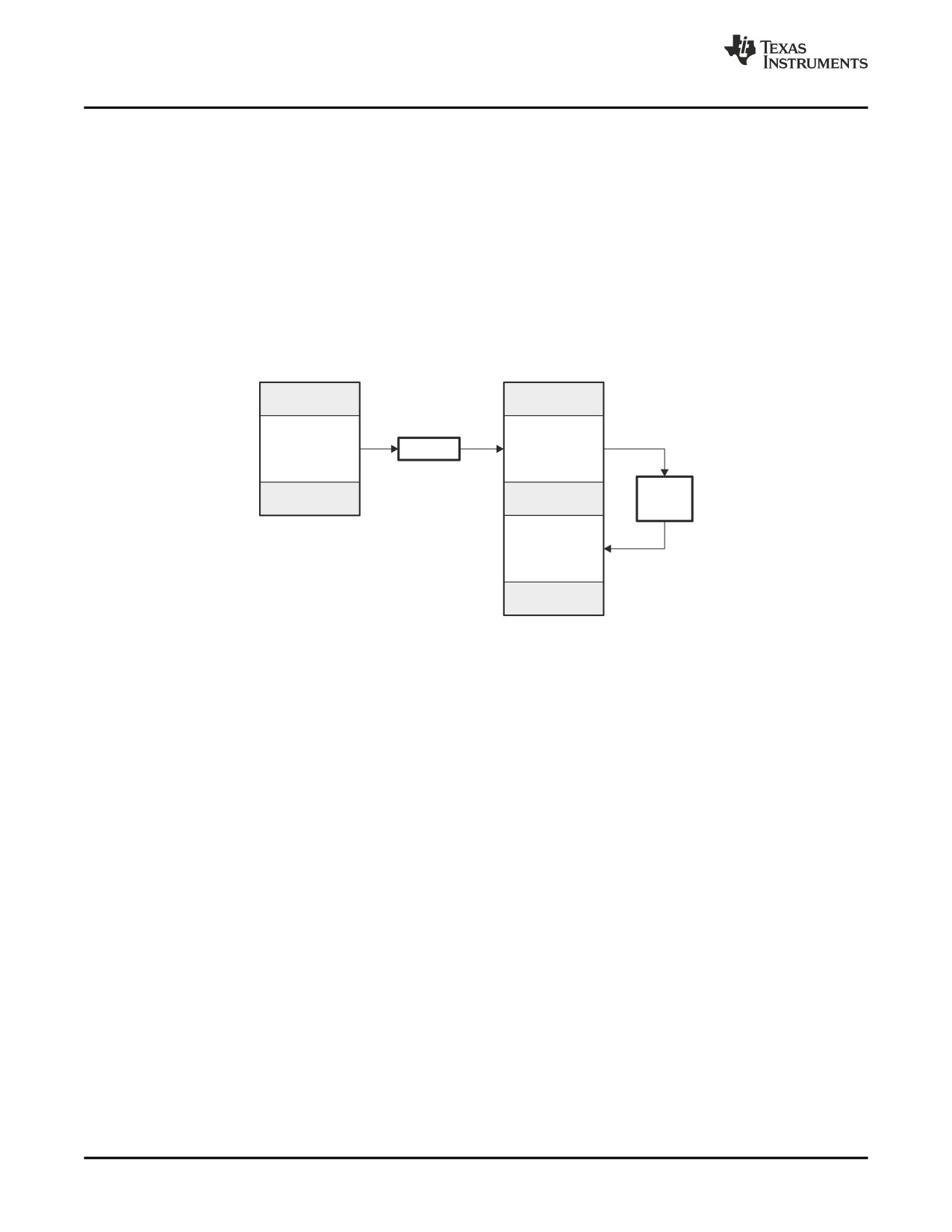
Linking C/C++ Code
7.17.4
Autoinitialization of Variables at Run Time
Autoinitializing variables at run time is the default method of autoinitialization. To use this method, invoke
the linker with the --rom_model option.
Using this method, the .cinit section is loaded into memory along with all the other initialized sections. The
linker defines a special symbol called cinit that points to the beginning of the initialization tables in
memory. When the program begins running, the C boot routine copies data from the tables (pointed to by
.cinit) into the specified variables in the .bss section. This allows initialization data to be stored in slow
external memory and copied to fast external memory each time the program starts.
Figure 7-5 illustrates autoinitialization at run time. Use this method in any system where your application
runs from code burned into slow external memory.
Figure 7-5. Autoinitialization at Run Time
Object file
Memory
cint
Initialization
.cinit
Loader
tables
section
(EXT_MEM)
Boot
routine
.bss
section
(D_MEM)
7.17.5
Initialization of Variables at Load Time
Initialization of variables at load time enhances performance by reducing boot time and by saving the
memory used by the initialization tables. To use this method, invoke the linker with the --ram_model
option.
When you use the --ram_model linker option, the linker sets the STYP_COPY bit in the .cinit section's
header. This tells the loader not to load the .cinit section into memory. (The .cinit section occupies no
space in the memory map.) The linker also sets the cinit symbol to -1 (normally, cinit points to the
beginning of the initialization tables). This indicates to the boot routine that the initialization tables are not
present in memory; accordingly, no run-time initialization is performed at boot time.
A loader must be able to perform the following tasks to use initialization at load time:
• Detect the presence of the .cinit section in the object file.
• Determine that STYP_COPY is set in the .cinit section header, so that it knows not to copy the .cinit
section into memory.
• Understand the format of the initialization tables.
Figure 7-6 illustrates the initialization of variables at load time.
206
Linker Description
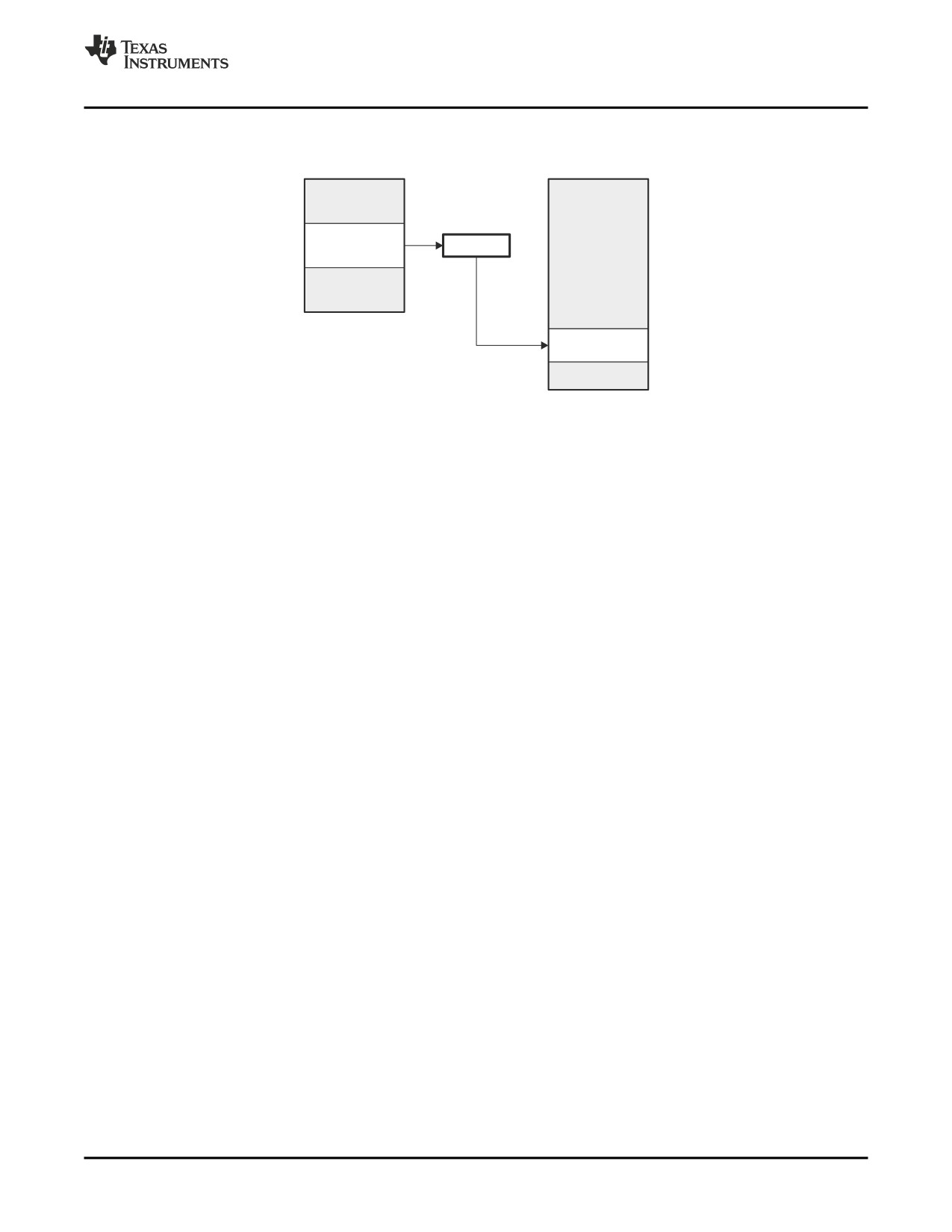
Linker Example
Figure 7-6. Initialization at Load Time
Object file
Memory
.cinit
Loader
.bss
7.17.6
The --rom_model and --ram_model Linker Options
The following list outlines what happens when you invoke the linker with the --ram_model or --rom_model
option.
• The symbol _c_int00 is defined as the program entry point. The _c_int00 symbol is the start of the C
boot routine in boot.obj; referencing _c_int00 ensures that boot.obj is automatically linked in from the
appropriate run-time-support library.
• The .cinit output section is padded with a termination record to designate to the boot routine
(autoinitialize at run time) or the loader (initialize at load time) when to stop reading the initialization
tables.
• When you initialize at load time (--ram_model option):
- The linker sets cinit to -1. This indicates that the initialization tables are not in memory, so no
initialization is performed at run time.
- The STYP_COPY flag (0010h) is set in the .cinit section header. STYP_COPY is the special
attribute that tells the loader to perform initialization directly and not to load the .cinit section into
memory. The linker does not allocate space in memory for the .cinit section.
• When you autoinitialize at run time (--rom_model option), the linker defines cinit as the starting address
of the .cinit section. The C boot routine uses this symbol as the starting point for autoinitialization.
7.18
Linker Example
This example links three object files named demo.obj, ctrl.obj, and tables.obj and creates a program called
demo.out.
Assume that target memory has the following program memory configuration:
Address Range
Contents
0x00000000 to 0x00001000
SLOW_MEM
0x00001000 to 0x00002000
FAST_MEM
0x08000000 to 0x08000400
EEPROM
The output sections are constructed from the following input sections:
• Executable code, contained in the .text sections of demo.obj, ctrl.obj, and tables.obj, must be linked
into FAST_MEM.
• A set of interrupt vectors, contained in the .intvecs section of tables.obj, must be linked at address
0x00000000.
• A table of coefficients, contained in the .data section of tables.obj, must be linked into EEPROM. The
remainder of block EEPROM must be initialized to the value 0xFF00FF00.
Linker Description
207
Linker Example
• A set of variables, contained in the .bss section of ctrl.obj, must be linked into SLOW_MEM and
preinitialized to 0x00000100.
• The .bss sections of demo.obj and tables.obj must be linked into SLOW_MEM.
Example 7-23 shows the link command file for this example. Example 7-24 shows the map file.
Example 7-23. Linker Command File, demo.cmd
/**********************************************************************/
/****
Specify Linker Options
****/
/**********************************************************************/
-e SETUP
/*
Define the program entry point
*/
-o demo.out
/*
Name the output file
*/
-m demo.map
/*
Create an output map
*/
/**********************************************************************/
/****
Specify the Input Files
****/
/**********************************************************************/
demo.objctrl.objtables.obj
/**********************************************************************/
/****
Specify the Memory Configuration
****/
/**********************************************************************/
MEMORY
{
FAST_MEM
: org = 0x00000000
len = 0x00001000
SLOW_MEM
: org = 0x00001000
len = 0x00001000
EEPROM
: org = 0x08000000
len = 0x00000400
}
/**********************************************************************/
/****
Specify the Output Sections
****/
/**********************************************************************/
SECTIONS
{
.text
: {} > FAST_MEM
/* Link all .text sections into ROM
*/
.intvecs : {} > 0x0
/* Link interrupt vectors at 0x0
*/
.data
:
/* Link .data sections
*/
{
tables.obj(.data)
. = 0x400;
/* Create hole at end of block
*/
} = 0xFF00FF00 > EEPROM
/* Fill and link into EEPROM
*/
ctrl_vars:
/* Create new ctrl_vars section
*/
{
ctrl.obj(.bss)
} = 0x00000100 > SLOW_MEM /* Fill with 0x100 and link into RAM
*/
.bss
: {} > SLOW_MEM
/* Link remaining .bss sections into RAM */
}
/**********************************************************************/
/****
End of Command File
****/
/**********************************************************************/
Invoke the linker by entering the following command:
cl6x
--run_linker demo.cmd
This creates the map file shown in Example 7-24 and an output file called demo.out that can be run on a
TMS320C6000.
208
Linker Description
Linker Example
Example 7-24. Output Map File, demo.map
OUTPUT FILE NAME:
<demo.out>
ENTRY POINT SYMBOL: 0
MEMORY CONFIGURATION
name
origin
length
used
attributes
fill
--------
--------
---------
--------
----------
--------
FAST_MEM
00000000
000001000
00000078
RWIX
SLOW_MEM
00001000
000001000
00000502
RWIX
EEPROM
08000000
000000400
00000400
RWIX
SECTION ALLOCATION MAP
output
attributes/
section
page
origin
length
input sections
--------
----
----------
----------
----------------
.text
0
00000000
00000064
00000000
00000030
demo.obj (.text)
00000030
00000000
tables.obj (.text)
00000030
00000010
--HOLE-- [fill = 00000000]
00000040
00000024
ctrl.obj (.text)
.intvecs
0
00000000
00000014
00000000
00000014
tables.obj (.intvecs)
.data
0
08000000
00000400
08000000
00000004
tables.obj (.data)
08000004
000003fc
--HOLE-- [fill = ff00ff00]
08000400
00000000
ctrl.obj (.data)
08000400
00000000
demo.obj (.data)
ctrl_vars
0
00001000
00000500
00001000
00000500
ctrl.obj (.bss) [fill = 00000100]
.bss
0
00001500
00000002
UNINITIALIZED
00001500
00000002
demo.obj (.bss)
00001502
00000000
tables.obj (.bss)
GLOBAL SYMBOLS
address name
address name
-------- ----
-------- ----
00001500
$bss
00000000 .text
00001500 .bss
00000000 _x42
08000000 .data
00000018 _SETUP
00000000 .text
00000040 _fill_tab
00000018 _SETUP
00000064 etext
00000040 _fill_tab
00001500
$bss
00000000 _x42
00001500 .bss
08000400 edata
00001502 end
00001502 end
08000000 gvar
00000064 etext
08000000 .data
08000000 gvar
08000400 edata
[11 symbols]
Linker Description
209
210
Linker Description