TMS320C6000 Assembly Language Tools v 6.1. User's Guide - page 1
TMS320C6000 Assembly Language Tools
v 6.1
User's Guide
Literature Number: SPRU186Q
May 2008
Contents
Preface
13
1
Introduction to the Software Development Tools
17
1.1
Software Development Tools Overview
18
1.2
Tools Descriptions
19
2
Introduction to Object Modules
21
2.1
Sections
22
2.2
How the Assembler Handles Sections
23
2.2.1
Uninitialized Sections
23
2.2.2
Initialized Sections
24
2.2.3
Named Sections
25
2.2.4
Subsections
25
2.2.5
Section Program Counters
26
2.2.6
Using Sections Directives
26
2.3
How the Linker Handles Sections
29
2.3.1
Default Memory Allocation
29
2.3.2
Placing Sections in the Memory Map
30
2.4
Relocation
30
2.5
Run-Time Relocation
32
2.6
Loading a Program
32
2.7
Symbols in an Object File
33
2.7.1
External Symbols
33
2.7.2
The Symbol Table
33
3
Assembler Description
35
3.1
Assembler Overview
36
3.2
The Assembler's Role in the Software Development Flow
37
3.3
Invoking the Assembler
38
3.4
Naming Alternate Directories for Assembler Input
39
3.4.1
Using the --include_path Assembler Option
39
3.4.2
Using the C6X_A_DIR Environment Variable
40
3.5
Source Statement Format
41
3.5.1
Label Field
42
3.5.2
Mnemonic Field
42
3.5.3
Unit Specifier Field
43
3.5.4
Operand Field
43
3.5.5
Comment Field
43
3.6
Constants
44
3.6.1
Binary Integers
44
3.6.2
Octal Integers
44
3.6.3
Decimal Integers
44
3.6.4
Hexadecimal Integers
45
Contents
3
3.6.5
Character Constants
45
3.6.6
Assembly-Time Constants
45
3.7
Character Strings
46
3.8
Symbols
46
3.8.1
Labels
46
3.8.2
Local Labels
46
3.8.3
Symbolic Constants
48
3.8.4
Defining Symbolic Constants (--asm_define Option)
49
3.8.5
Predefined Symbolic Constants
50
3.8.6
Substitution Symbols
51
3.9
Expressions
52
3.9.1
Operators
52
3.9.2
Expression Overflow and Underflow
52
3.9.3
Well-Defined Expressions
53
3.9.4
Conditional Expressions
53
3.9.5
Legal Expressions
53
3.9.6
Expression Examples
54
3.10
Source Listings
55
3.11
Debugging Assembly Source
57
3.12
Cross-Reference Listings
58
4
Assembler Directives
59
4.1
Directives Summary
60
4.2
Directives That Define Sections
63
4.3
Directives That Initialize Constants
65
4.4
Directives That Perform Alignment and Reserve Space
66
4.5
Directives That Format the Output Listings
67
4.6
Directives That Reference Other Files
68
4.7
Directives That Enable Conditional Assembly
69
4.8
Directives That Define Unions or Structures
69
4.9
Directives That Define Symbols at Assembly Time
70
4.10
Miscellaneous Directives
71
4.11
Directives Reference
71
5
Macro Description
123
5.1
Using Macros
124
5.2
Defining Macros
124
5.3
Macro Parameters/Substitution Symbols
126
5.3.1
Directives That Define Substitution Symbols
127
5.3.2
Built-In Substitution Symbol Functions
127
5.3.3
Recursive Substitution Symbols
128
5.3.4
Forced Substitution
129
5.3.5
Accessing Individual Characters of Subscripted Substitution Symbols
129
5.3.6
Substitution Symbols as Local Variables in Macros
130
5.4
Macro Libraries
131
5.5
Using Conditional Assembly in Macros
132
5.6
Using Labels in Macros
134
5.7
Producing Messages in Macros
135
5.8
Using Directives to Format the Output Listing
136
5.9
Using Recursive and Nested Macros
136
4
Contents
5.10
Macro Directives Summary
138
6
Archiver Description
139
6.1
Archiver Overview
140
6.2
The Archiver's Role in the Software Development Flow
141
6.3
Invoking the Archiver
142
6.4
Archiver Examples
143
7
Linker Description
145
7.1
Linker Overview
146
7.2
The Linker's Role in the Software Development Flow
147
7.3
Invoking the Linker
148
7.4
Linker Options
149
7.4.1
Wild Cards in File, Section, and Symbol Patterns
150
7.4.2
Relocation Capabilities (--absolute_exe and --relocatable Options)
150
7.4.3
Allocate Memory for Use by the Loader to Pass Arguments (--arg_size Option)
151
7.4.4
Compress DWARF Information (--compress_dwarf Option)
151
7.4.5
Control Linker Diagnostics
152
7.4.6
Disable Automatic Library Selection (--disable_auto_rts Option)
152
7.4.7
Disable Conditional Linking (--disable_clink Option)
152
7.4.8
Link Command File Preprocessing (--disable_pp, --define and --undefine Options)
153
7.4.9
Define an Entry Point (--entry_point Option)
154
7.4.10
Set Default Fill Value (--fill_value Option)
154
7.4.11
Generate List of Dead Functions (--generate_dead_funcs_list Option)
154
7.4.12
Using Function Subsections (--gen_func_subsections Option)
154
7.4.13
Define Heap Size (--heap_size Option)
155
7.4.14
Alter the Library Search Algorithm (--library Option, --search_path Option, and C6X_C_DIR
Environment Variable)
155
7.4.15
Make a Symbol Global (--make_global Option)
157
7.4.16
Make All Global Symbols Static (--make_static Option)
157
7.4.17
Create a Map File (--map_file Option)
157
7.4.18
Managing Map File Contents (--mapfile_contents Option)
158
7.4.19
Disable Name Demangling (--no_demangle)
159
7.4.20
Disable Merge of Symbolic Debugging Information (--no_sym_merge Option)
159
7.4.21
Strip Symbolic Information (--no_sym_table Option)
160
7.4.22
Name an Output Module (--output_file Option)
160
7.4.23
C Language Options (--ram_model and --rom_model Options)
160
7.4.24
Exhaustively Read and Search Libraries (--reread_libs and --priority Options)
160
7.4.25
Create an Absolute Listing File (--run_abs Option)
161
7.4.26
Designate Header Path (--runtime Option)
161
7.4.27
Scan All Libraries for Duplicate Symbol Definitions (--scan_libraries)
161
7.4.28
Define Stack Size (--stack_size Option)
161
7.4.29
Enforce Strict Compatibility (--strict_compatibility Option)
162
7.4.30
Mapping of Symbols (--symbol_map Option)
162
7.4.31
Generate Far Call Trampolines (--trampolines Option)
162
7.4.32
Introduce an Unresolved Symbol (--undef_sym Option)
164
7.4.33
Display a Message When an Undefined Output Section Is Created (--warn_sections Option)
164
7.4.34
Generate XML Link Information File (--xml_link_info Option)
164
7.5
Linker Command Files
165
7.5.1
Reserved Names in Linker Command Files
166
Contents
5
7.5.2
Constants in Linker Command Files
166
7.6
Object Libraries
167
7.7
The MEMORY Directive
168
7.7.1
Default Memory Model
168
7.7.2
MEMORY Directive Syntax
168
7.8
The SECTIONS Directive
170
7.8.1
SECTIONS Directive Syntax
170
7.8.2
Allocation
172
7.8.3
Specifying Input Sections
175
7.8.4
Using Multi-Level Subsections
177
7.8.5
Allocation Using Multiple Memory Ranges
178
7.8.6
Automatic Splitting of Output Sections Among Non-Contiguous Memory Ranges
178
7.8.7
Allocating an Archive Member to an Output Section
179
7.9
Specifying a Section's Run-Time Address
180
7.9.1
Specifying Load and Run Addresses
181
7.9.2
Uninitialized Sections
181
7.9.3
Referring to the Load Address by Using the .label Directive
181
7.10
Using UNION and GROUP Statements
183
7.10.1
Overlaying Sections With the UNION Statement
183
7.10.2
Grouping Output Sections Together
185
7.10.3
Nesting UNIONs and GROUPs
185
7.10.4
Checking the Consistency of Allocators
186
7.10.5
Naming UNIONs and GROUPs
187
7.11
Special Section Types (DSECT, COPY, and NOLOAD)
187
7.12
Default Allocation Algorithm
188
7.12.1
How the Allocation Algorithm Creates Output Sections
188
7.12.2
Reducing Memory Fragmentation
189
7.13
Assigning Symbols at Link Time
189
7.13.1
Syntax of Assignment Statements
189
7.13.2
Assigning the SPC to a Symbol
190
7.13.3
Assignment Expressions
190
7.13.4
Symbols Defined by the Linker
191
7.13.5
Assigning Exact Start, End, and Size Values of a Section to a Symbol
192
7.13.6
Why the Dot Operator Does Not Always Work
192
7.13.7
Address and Dimension Operators
193
7.14
Creating and Filling Holes
194
7.14.1
Initialized and Uninitialized Sections
194
7.14.2
Creating Holes
195
7.14.3
Filling Holes
196
7.14.4
Explicit Initialization of Uninitialized Sections
196
7.15
Linker-Generated Copy Tables
197
7.15.1
A Current Boot-Loaded Application Development Process
197
7.15.2
An Alternative Approach
197
7.15.3
Overlay Management Example
198
7.15.4
The table() Operator
198
7.15.5
Boot-Time Copy Tables
199
7.15.6
Using the table() Operator to Manage Object Components
199
7.15.7
Copy Table Contents
200
7.15.8
General Purpose Copy Routine
201
6
Contents
2008
7.15.9
Linker-Generated Copy Table Sections and Symbols
201
7.15.10
Splitting Object Components and Overlay Management
202
7.16
Partial (Incremental) Linking
204
7.17
Linking C/C++ Code
205
7.17.1
Run-Time Initialization
205
7.17.2
Object Libraries and Run-Time Support
205
7.17.3
Setting the Size of the Stack and Heap Sections
205
7.17.4
Autoinitialization of Variables at Run Time
206
7.17.5
Initialization of Variables at Load Time
206
7.17.6
The --rom_model and --ram_model Linker Options
207
7.18
Linker Example
207
8
Absolute Lister Description
211
8.1
Producing an Absolute Listing
212
8.2
Invoking the Absolute Lister
213
8.3
Absolute Lister Example
214
9
Cross-Reference Lister Description
219
9.1
Producing a Cross-Reference Listing
220
9.2
Invoking the Cross-Reference Lister
221
9.3
Cross-Reference Listing Example
221
10
Object File Utilities Descriptions
223
10.1
Invoking the Object File Display Utility
224
10.2
Invoking the Disassembler
225
10.3
Invoking the Name Utility
226
10.4
Invoking the Strip Utility
227
11
Hex Conversion Utility Description
229
11.1
The Hex Conversion Utility's Role in the Software Development Flow
230
11.2
Invoking the Hex Conversion Utility
231
11.2.1
Invoking the Hex Conversion Utility From the Command Line
231
11.2.2
Invoking the Hex Conversion Utility With a Command File
233
11.3
Understanding Memory Widths
234
11.3.1
Target Width
234
11.3.2
Specifying the Memory Width
235
11.3.3
Partitioning Data Into Output Files
236
11.3.4
Specifying Word Order for Output Words
238
11.4
The ROMS Directive
238
11.4.1
When to Use the ROMS Directive
239
11.4.2
An Example of the ROMS Directive
240
11.5
The SECTIONS Directive
242
11.6
Excluding a Specified Section
243
11.7
Assigning Output Filenames
244
11.8
Image Mode and the -fill Option
245
11.8.1
Generating a Memory Image
245
11.8.2
Specifying a Fill Value
245
11.8.3
Steps to Follow in Using Image Mode
245
11.9
Building a Table for an On-Chip Boot Loader
246
11.9.1
Description of the Boot Table
246
11.9.2
The Boot Table Format
246
Contents
7
11.9.3
How to Build the Boot Table
247
11.9.4
Using the C6000 Boot Loader
248
11.10
Controlling the ROM Device Address
249
11.11
Description of the Object Formats
250
11.11.1
ASCII-Hex Object Format (-a Option)
250
11.11.2
Intel MCS-86 Object Format (-i Option)
251
11.11.3
Motorola Exorciser Object Format (-m Option)
252
11.11.4
Texas Instruments SDSMAC Object Format (-t Option)
253
11.11.5
TI-TXT Hex Format (--ti_txt Option)
254
11.11.6
Extended Tektronix Object Format (-x Option)
255
12
Sharing C/C++ Header Files With Assembly Source
257
12.1
Overview of the .cdecls Directive
258
12.2
Notes on C/C++ Conversions
258
12.2.1
Comments
258
12.2.2
Conditional Compilation (#if/#else/#ifdef/etc.)
259
12.2.3
Pragmas
259
12.2.4
The #error and #warning Directives
259
12.2.5
Predefined symbol _ _ASM_HEADER_ _
259
12.2.6
Usage Within C/C++ asm( ) Statements
259
12.2.7
The #include Directive
259
12.2.8
Conversion of #define Macros
259
12.2.9
The #undef Directive
260
12.2.10
Enumerations
260
12.2.11
C Strings
260
12.2.12
C/C++ Built-In Functions
261
12.2.13
Structures and Unions
261
12.2.14
Function/Variable Prototypes
261
12.2.15
C Constant Suffixes
262
12.2.16
Basic C/C++ Types
262
12.3
Notes on C++ Specific Conversions
262
12.3.1
Name Mangling
262
12.3.2
Derived Classes
262
12.3.3
Templates
263
12.3.4
Virtual Functions
263
12.4
New Assembler Support
263
12.4.1
Enumerations (.enum/.emember/.endenum)
263
12.4.2
The .define Directive
263
12.4.3
The .undefine/.unasg Directives
263
12.4.4
The $defined( ) Directive
264
12.4.5
The $sizeof Built-In Function
264
12.4.6
Structure/Union Alignment & $alignof( )
264
12.4.7
The .cstring Directive
264
A
Symbolic Debugging Directives
265
A.1
DWARF Debugging Format
266
A.2
COFF Debugging Format
266
A.3
Debug Directive Syntax
267
B
XML Link Information File Description
269
B.1
XML Information File Element Types
270
8
Contents
2008
B.2
Document Elements
270
B.2.1
Header Elements
270
B.2.2
Input File List
271
B.2.3
Object Component List
272
B.2.4
Logical Group List
273
B.2.5
Placement Map
275
B.2.6
Far Call Trampoline List
276
B.2.7
Symbol Table
277
C Glossary
279
Index
284
Contents
9
List of Figures
1-1
TMS320C6000 Software Development Flow
18
2-1
Partitioning Memory Into Logical Blocks
22
2-2
Using Sections Directives Example
27
2-3
Object Code Generated by the File in Figure 2-2
28
2-4
Combining Input Sections to Form an Executable Object Module
29
3-1
The Assembler in the TMS320C6000 Software Development Flow
37
3-2
Example Assembler Listing
56
4-1
The .field Directive
65
4-2
Initialization Directives
66
4-3
The .align Directive
66
4-4
The .space and .bes Directives
67
4-5
Double-Precision Floating-Point Format
85
4-6
The .field Directive
91
4-7
Single-Precision Floating-Point Format
92
4-8
The .usect Directive
121
6-1
The Archiver in the TMS320C6000 Software Development Flow
141
7-1
The Linker in the TMS320C6000 Software Development Flow
147
7-2
Section Allocation Defined by Example 7-4
172
7-3
Run-Time Execution of Example 7-9
183
7-4
Memory Allocation Shown in Example 7-11 and Example 7-12
184
7-5
Autoinitialization at Run Time
206
7-6
Initialization at Load Time
207
8-1
Absolute Lister Development Flow
212
9-1
The Cross-Reference Lister in the TMS320C6000 Software Development Flow
220
11-1
The Hex Conversion Utility in the TMS320C6000 Software Development Flow
230
11-2
Hex Conversion Utility Process Flow
234
11-3
Object File Data and Memory Widths
235
11-4
Data, Memory, and ROM Widths
237
11-5
The infile.out File Partitioned Into Four Output Files
240
11-6
ASCII-Hex Object Format
250
11-7
Intel Hexadecimal Object Format
251
11-8
Motorola-S Format
252
11-9
TI-Tagged Object Format
253
11-10
TI-TXT Object Format
254
11-11
Extended Tektronix Object Format
255
10
List of Figures
List of Tables
3-1
TMS320C6000 Assembler Options
38
3-2
CPU Control Registers
50
3-3
Processor Symbols
51
3-4
Assembler Version Symbols
51
3-5
Operators Used in Expressions (Precedence)
52
3-6
Symbol Attributes
58
4-1
Directives That Define Sections
60
4-2
Directives That Initialize Constants (Data and Memory)
60
4-3
Directives That Perform Alignment and Reserve Space
61
4-4
Directives That Format the Output Listing
61
4-5
Directives That Reference Other Files
61
4-6
Directives That Enable Conditional Assembly
62
4-7
Directives That Define Unions or Structures
62
4-8
Directives That Define Symbols at Assembly Time
62
4-9
Directives That Perform Miscellaneous Functions
63
5-1
Substitution Symbol Functions and Return Values
128
5-2
Creating Macros
138
5-3
Manipulating Substitution Symbols
138
5-4
Conditional Assembly
138
5-5
Producing Assembly-Time Messages
138
5-6
Formatting the Listing
138
7-1
Linker Options Summary
149
7-2
Groups of Operators Used in Expressions (Precedence)
191
9-1
Symbol Attributes in Cross-Reference Listing
222
11-1
Basic Hex Conversion Utility Options
232
11-2
Boot-Loader Options
247
11-3
Options for Specifying Hex Conversion Formats
250
A-1
Symbolic Debugging Directives
267
List of Tables
11
12
List of Tables
Preface
Read This First
About This Manual
The TMS320C6000 Assembly Language Tools User's Guide explains how to use these assembly
language tools:
• Assembler
• Archiver
• Linker
• Absolute lister
• Cross-reference lister
• Disassembler
• Object file display utility
• Name utility
• Strip utility
• Hex conversion utility
How to Use This Manual
This book helps you learn how to use the Texas Instruments assembly language tools designed
specifically for the TMS320C6000™ 32-bit devices. This book consists of four parts:
• Introductory information, consisting of Chapter 1 and Chapter 2, gives you an overview of the
assembly language development tools. It also discusses object modules, which helps you to use the
TMS320C6000 tools more efficiently. Read Chapter 2, Introduction to Object Modules, before using the
assembler and linker.
• Assembler description, consisting of Chapter 3 through Chapter 5, contains detailed information
about using the assembler. This portion explains how to invoke the assembler and discusses source
statement format, valid constants and expressions, assembler output, and assembler directives. It also
describes the macro language.
• Additional assembly language tools description, consisting of Chapter 6 through Chapter 11,
describes in detail each of the tools provided with the assembler to help you create executable object
files. For example, Chapter 7 explains how to invoke the linker, how the linker operates, and how to
use linker directives; Chapter 11 explains how to use the hex conversion utility.
• Reference material, consisting of Appendix A through Appendix C, provides supplementary
information including symbolic debugging directives that the TMS320C6000 C/C++ compiler uses. It
also provides a description of the XML link information file and a glossary.
Read This First
13
Notational Conventions
Notational Conventions
This document uses the following conventions:
•
Program listings, program examples, and interactive displays are shown in a special typeface.
Interactive displays use a bold version of the special typeface to distinguish commands that you enter
from items that the system displays (such as prompts, command output, error messages, etc.).
Here is a sample of C code:
#include <stdio.h>
main()
{
printf("hello, cruel world\n";
}
•
In syntax descriptions, the instruction, command, or directive is in a bold typeface and parameters are
in an italic typeface. Portions of a syntax that are in bold should be entered as shown; portions of a
syntax that are in italics describe the type of information that should be entered.
•
Square brackets ( [ and ] ) identify an optional parameter. If you use an optional parameter, you specify
the information within the brackets. Unless the square brackets are in the bold typeface, do not enter
the brackets themselves. The following is an example of a command that has an optional parameter:
cl6x [options] [filenames] [--run_linker [link_options] [object files]]
•
Braces ( { and } ) indicate that you must choose one of the parameters within the braces; you do not
enter the braces themselves. This is an example of a command with braces that are not included in the
actual syntax but indicate that you must specify either the --rom_model or --ram_model option:
cl6x --run_linker
{--rom_model | --ram_model} filenames [--output_file=name.out]
--library= libraryname
•
In assembler syntax statements, column 1 is reserved for the first character of a label or symbol. If the
label or symbol is optional, it is usually not shown. If it is a required parameter, it is shown starting
against the left margin of the box, as in the example below. No instruction, command, directive, or
parameter, other than a symbol or label, can begin in column 1.
symbol .usect "section name", size in bytes[, alignment]
•
Some directives can have a varying number of parameters. For example, the .byte directive can have
up to 100 parameters. This syntax is shown as [, ..., parameter].
•
The TMS320C62x™, C64x™, and C67x™ core is referred to as TMS320C6000 or C6000™.
•
Following are other symbols and abbreviations used throughout this document:
Symbol
Definition
B,b
Suffix — binary integer
H, h
Suffix — hexadecimal integer
LSB
Least significant bit
MSB
Most significant bit
0x
Prefix — hexadecimal integer
Q, q
Suffix — octal integer
14
Read This First
Related Documentation From Texas Instruments
Related Documentation From Texas Instruments
The following books describe the TMS320C6000 devices and related support tools. To obtain a copy of
any of these TI documents, call the Texas Instruments Literature Response Center at (800) 477-8924.
When ordering, please identify the book by its title and literature number.
SPRU187 — TMS320C6000 Optimizing Compiler v 6.1 User's Guide. Describes the TMS320C6000 C
compiler and the assembly optimizer. This C compiler accepts ANSI standard C source code and
produces assembly language source code for the TMS320C6000 platform of devices (including the
C64x+ and C67x+ generations). The assembly optimizer helps you optimize your assembly code.
SPRU198 — TMS320C6000 Programmer's Guide. Reference for programming the TMS320C6000
digital signal processors (DSPs). Before you use this manual, you should install your code
generation and debugging tools. Includes a brief description of the C6000 DSP architecture and
code development flow, includes C code examples and discusses optimization methods for the C
code, describes the structure of assembly code and includes examples and discusses optimizations
for the assembly code, and describes programming considerations for the C64x DSP.
SPRU190 — TMS320C6000 DSP Peripherals Overview Reference Guide. Provides an overview and
briefly describes the peripherals available on the TMS320C6000 family of digital signal processors
(DSPs).
SPRU731 — TMS320C62x DSP CPU and Instruction Set Reference Guide. Describes the CPU
architecture, pipeline, instruction set, and interrupts for the TMS320C62x digital signal processors
(DSPs) of the TMS320C6000 DSP family. The C62x DSP generation comprises fixed-point devices
in the C6000 DSP platform.
SPRU732 — TMS320C64x/C64x+ DSP CPU and Instruction Set Reference Guide. Describes the CPU
architecture, pipeline, instruction set, and interrupts for the TMS320C64x and TMS320C64x+ digital
signal processors (DSPs) of the TMS320C6000 DSP family. The C64x/C64x+ DSP generation
comprises fixed-point devices in the C6000 DSP platform. The C64x+ DSP is an enhancement of
the C64x DSP with added functionality and an expanded instruction set.
SPRU733 — TMS320C67x/C67x+ DSP CPU and Instruction Set Reference Guide. Describes the CPU
architecture, pipeline, instruction set, and interrupts for the TMS320C67x and TMS320C67x+ digital
signal processors (DSPs) of the TMS320C6000 DSP platform. The C67x/C67x+ DSP generation
comprises floating-point devices in the C6000 DSP platform. The C67x+ DSP is an enhancement of
the C67x DSP with added functionality and an expanded instruction set.
SPRAAO8 — Common Object File Format Application Report. Provides supplementary information on
the internal format of COFF object files. Much of this information pertains to the symbolic
debugging information that is produced by the C compiler.
Read This First
15
16
Read This First
Chapter 1
Introduction to the Software Development Tools
The TMS320C6000™ is supported by a set of software development tools, which includes an optimizing
C/C++ compiler, an assembly optimizer, an assembler, a linker, and assorted utilities. This chapter
provides an overview of these tools.
The TMS320C6000 is supported by the following assembly language development tools:
• Assembler
• Archiver
• Linker
• Absolute lister
• Cross-reference lister
• Object file display utility
• Name utility
• Strip utility
• Hex conversion utility
This chapter shows how these tools fit into the general software tools development flow and gives a brief
description of each tool. For convenience, it also summarizes the C/C++ compiler and debugging tools.
For detailed information on the compiler and debugger, and for complete descriptions of the
TMS320C6000, refer to books listed in Related Documentation From Texas Instruments.
Topic
Page
1.1
Software Development Tools Overview
18
1.2
Tools Descriptions
19
Introduction to the Software Development Tools
17
Software Development Tools Overview
1.1
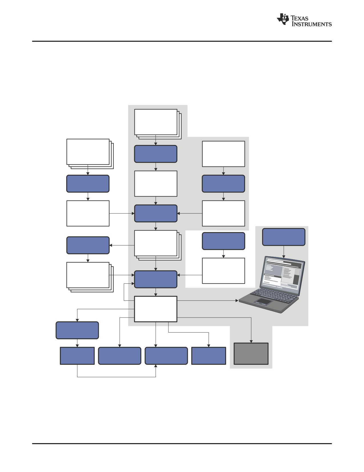
Software Development Tools Overview
Figure 1-1 shows the TMS320C6000 software development flow. The shaded portion highlights the most
common development path; the other portions are optional. The other portions are peripheral functions
that enhance the development process.
Figure 1-1. TMS320C6000 Software Development Flow
C/C++
source
files
Macro
source
C/C++
Linear
files
compiler
assembly
Assembler
Assembly
Archiver
source
optimizer
Assembly
Macro
Assembler
optimized
library
file
Debugging
Library-build
Object
tools
process
Archiver
files
Run-time-
Library of
support
object
library
Linker
files
Executable
object file
Hex-conversion
utility
EPROM
Cross-reference
Object file
C6000
Absolute lister
programmer
lister
utilities
18
Introduction to the Software Development Tools
Tools Descriptions
1.2
Tools Descriptions
The following list describes the tools that are shown in Figure 1-1:
•
The C/C++ compiler accepts C/C++ source code and produces TMS320C6000 assembly language
source code. A shell program, an optimizer, and an interlist utility are included in the compiler
package:
- The shell program enables you to compile, assemble, and link source modules in one step.
- The optimizer modifies code to improve the efficiency of C/C++ programs.
- The interlist utility interlists C/C++ source statements with assembly language output to correlate
code produced by the compiler with your source code.
See the TMS320C6000 Optimizing Compiler User's Guide for more information.
•
The assembler translates assembly language source files into machine language object modules.
Source files can contain instructions, assembler directives, and macro directives. You can use
assembler directives to control various aspects of the assembly process, such as the source listing
format, data alignment, and section content. See Chapter 3 through Chapter 5. See the TMS320C6000
CPU and Instruction Set Reference Guide for detailed information on the assembly language
instruction set.
•
The linker combines object files into a single executable object module. As it creates the executable
module, it performs relocation and resolves external references. The linker accepts relocatable object
modules (created by the assembler) as input. It also accepts archiver library members and output
modules created by a previous linker run. Link directives allow you to combine object file sections, bind
sections or symbols to addresses or within memory ranges, and define or redefine global symbols. See
Chapter 7.
•
The archiver allows you to collect a group of files into a single archive file, called a library. For
example, you can collect several macros into a macro library. The assembler searches the library and
uses the members that are called as macros by the source file. You can also use the archiver to collect
a group of object files into an object library. The linker includes in the library the members that resolve
external references during the link. The archiver allows you to modify a library by deleting, replacing,
extracting, or adding members. See Chapter 6.
•
You can use the library-build process to build your own customized run-time-support library. See the
TMS320C6000 Optimizing Compiler User's Guide for more information.
•
The hex conversion utility converts an object file into TI-Tagged, ASCII-Hex, Intel, Motorola-S, or
Tektronix object format. The converted file can be downloaded to an EPROM programmer. See
Chapter 11.
•
The absolute lister uses linked object files to create .abs files. These files can be assembled to
produce a listing of the absolute addresses of object code. See Chapter 8.
•
The cross-reference lister uses object files to produce a cross-reference listing showing symbols,
their definition, and their references in the linked source files. See Chapter 9.
•
The main product of this development process is a module that can be executed in a TMS320C6000
device. You can use one of several debugging tools to refine and correct your code. Available products
include:
- An instruction-accurate and clock-accurate software simulator
- An XDS emulator
In addition, the following utilities are provided:
•
The object file display utility prints the contents of object files, executable files, and/or archive
libraries in both human readable and XML formats. See Section 10.1.
•
The name utility prints a list of names defined and referenced in a object or an executable file. See
Section 10.3.
•
The strip utility removes symbol table and debugging information from object and executable files.
See Section 10.4.
Introduction to the Software Development Tools
19
20
Introduction to the Software Development Tools
Chapter 2
Introduction to Object Modules
The assembler and linker create object modules that can be executed by a TMS320C6000™ device.
Object modules make modular programming easier because they encourage you to think in terms of
blocks of code and data when you write an assembly language program. These blocks are known as
sections. Both the assembler and the linker provide directives that allow you to create and manipulate
sections.
This chapter focuses on the concept and use of sections in assembly language programs.
Topic
Page
2.1
Sections
22
2.2
How the Assembler Handles Sections
23
2.3
How the Linker Handles Sections
29
2.4
Relocation
30
2.5
Run-Time Relocation
32
2.6
Loading a Program
32
2.7
Symbols in an Object File
33
Introduction to Object Modules
21
Sections
2.1
Sections
The smallest unit of an object file is called a section. A section is a block of code or data that occupies
contiguous space in the memory map with other sections. Each section of an object file is separate and
distinct. Object files usually contain three default sections:
.text section
usually contains executable code
.data section
usually contains initialized data
.bss section
usually reserves space for uninitialized variables
In addition, the assembler and linker allow you to create, name, and link named sections that are used like
the .data, .text, and .bss sections.
There are two basic types of sections:
Initialized sections
contain data or code. The .text and .data sections are initialized; named
sections created with the .sect assembler directive are also initialized.
Uninitialized sections
reserve space in the memory map for uninitialized data. The .bss section is
uninitialized; named sections created with the .usect assembler directive are
also uninitialized.
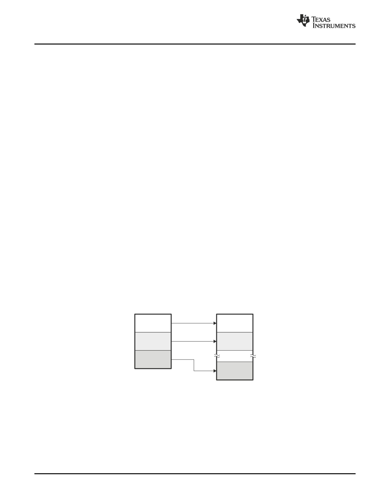
Several assembler directives allow you to associate various portions of code and data with the appropriate
sections. The assembler builds these sections during the assembly process, creating an object file
organized as shown in Figure 2-1.
One of the linker's functions is to relocate sections into the target system's memory map; this function is
called allocation. Because most systems contain several types of memory, using sections can help you
use target memory more efficiently. All sections are independently relocatable; you can place any section
into any allocated block of target memory. For example, you can define a section that contains an
initialization routine and then allocate the routine into a portion of the memory map that contains ROM.
Figure 2-1 shows the relationship between sections in an object file and a hypothetical target memory.
Figure 2-1. Partitioning Memory Into Logical Blocks
Object file
Target memory
.bss
RAM
.data
EEPROM
.text
ROM
22
Introduction to Object Modules
How the Assembler Handles Sections
2.2
How the Assembler Handles Sections
The assembler identifies the portions of an assembly language program that belong in a given section.
The assembler has five directives that support this function:
•
.bss
•
.usect
•
.text
•
.data
•
.sect
The .bss and .usect directives create uninitialized sections; the .text, .data, and .sect directives create
initialized sections.
You can create subsections of any section to give you tighter control of the memory map. Subsections are
created using the .sect and .usect directives. Subsections are identified with the base section name and a
subsection name separated by a colon; see Section 2.2.4.
Default Sections Directive
Note: If you do not use any of the sections directives, the assembler assembles everything into the
.text section.
2.2.1
Uninitialized Sections
Uninitialized sections reserve space in TMS320C6000 memory; they are usually allocated into RAM.
These sections have no actual contents in the object file; they simply reserve memory. A program can use
this space at run time for creating and storing variables.
Uninitialized data areas are built by using the .bss and .usect assembler directives.
• The .bss directive reserves space in the .bss section.
• The .usect directive reserves space in a specific uninitialized named section.
Each time you invoke the .bss or .usect directive, the assembler reserves additional space in the .bss or
the named section. The syntaxes for these directives are:
.bss symbol, size in bytes [, alignment [, bank offset] ]
symbol
.usect "section name", size in bytes [, alignment[, bank offset] ]
symbol
points to the first byte reserved by this invocation of the .bss or .usect directive. The
symbol corresponds to the name of the variable that you are reserving space for. It can
be referenced by any other section and can also be declared as a global symbol (with
the .global directive).
size in bytes
is an absolute expression. The .bss directive reserves size in bytes bytes in the .bss
section. The .usect directive reserves size in bytes bytes in section name. For both
directives, you must specify a size; there is no default value.
alignment
is an optional parameter. It specifies the minimum alignment in bytes required by the
space allocated. The default value is byte aligned. The value must be power of 2.
bank offset
is an optional parameter. It ensures that the space allocated to the symbol occurs on a
specific memory bank boundary. The bank offset measures the number of bytes to
offset from the alignment specified before assigning the symbol to that location.
section name
tells the assembler which named section to reserve space in. See Section 2.2.3.
Introduction to Object Modules
23
How the Assembler Handles Sections
The initialized section directives (.text, .data, and .sect) tell the assembler to stop assembling into the
current section and begin assembling into the indicated section. The .bss and .usect directives, however,
do not end the current section and begin a new one; they simply escape from the current section
temporarily. The .bss and .usect directives can appear anywhere in an initialized section without affecting
its contents. For an example, see Section 2.2.6.
The assembler treats uninitialized subsections (created with the .usect directive) in the same manner as
uninitialized sections. See Section 2.2.4, for more information on creating subsections.
2.2.2
Initialized Sections
Initialized sections contain executable code or initialized data. The contents of these sections are stored in
the object file and placed in TMS320C6000 memory when the program is loaded. Each initialized section
is independently relocatable and may reference symbols that are defined in other sections. The linker
automatically resolves these section-relative references.
Three directives tell the assembler to place code or data into a section. The syntaxes for these directives
are:
.text
.data
.sect " section name "
When the assembler encounters one of these directives, it stops assembling into the current section
(acting as an implied end of current section command). It then assembles subsequent code into the
designated section until it encounters another .text, .data, or .sect directive.
Sections are built through an iterative process. For example, when the assembler first encounters a .data
directive, the .data section is empty. The statements following this first .data directive are assembled into
the .data section (until the assembler encounters a .text or .sect directive). If the assembler encounters
subsequent .data directives, it adds the statements following these .data directives to the statements
already in the .data section. This creates a single .data section that can be allocated continuously into
memory.
Initialized subsections are created with the .sect directive. The assembler treats initialized subsections in
the same manner as initialized sections. See Section 2.2.4, for more information on creating subsections.
24
Introduction to Object Modules
How the Assembler Handles Sections
2.2.3
Named Sections
Named sections are sections that you create. You can use them like the default .text, .data, and .bss
sections, but they are assembled separately.
For example, repeated use of the .text directive builds up a single .text section in the object file. When
linked, this .text section is allocated into memory as a single unit. Suppose there is a portion of executable
code (perhaps an initialization routine) that you do not want allocated with .text. If you assemble this
segment of code into a named section, it is assembled separately from .text, and you can allocate it into
memory separately. You can also assemble initialized data that is separate from the .data section, and
you can reserve space for uninitialized variables that is separate from the .bss section.
Two directives let you create named sections:
• The .usect directive creates uninitialized sections that are used like the .bss section. These sections
reserve space in RAM for variables.
• The .sect directive creates initialized sections, like the default .text and .data sections, that can contain
code or data. The .sect directive creates named sections with relocatable addresses.
The syntaxes for these directives are:
symbol
.usect "section name", size in bytes [, alignment[, bank offset] ]
.sect "section name"
The section name parameter is the name of the section. Section names are significant to 200 characters.
You can create up to 32 767 separate named sections. For the .usect and .sect directives, a section name
can refer to a subsection; see Section 2.2.4 for details.
Each time you invoke one of these directives with a new name, you create a new named section. Each
time you invoke one of these directives with a name that was already used, the assembler assembles
code or data (or reserves space) into the section with that name. You cannot use the same names with
different directives. That is, you cannot create a section with the .usect directive and then try to use the
same section with .sect.
2.2.4
Subsections
Subsections are smaller sections within larger sections. Like sections, subsections can be manipulated by
the linker. Subsections give you tighter control of the memory map. You can create subsections by using
the .sect or .usect directive. The syntaxes for a subsection name are:
symbol
.usect "section name:subsection name", size in bytes [, alignment[, bank offset] ]
.sect "section name:subsection name"
A subsection is identified by the base section name followed by a colon and the name of the subsection. A
subsection can be allocated separately or grouped with other sections using the same base name. For
example, you create a subsection called _func within the .text section:
.sect ".text:_func"
Using the linker's SECTIONS directive, you can allocate .text:_func separately, or with all the .text
sections. See Section 7.8.1 for an example using subsections.
You can create two types of subsections:
• Initialized subsections are created using the .sect directive. See Section 2.2.2.
• Uninitialized subsections are created using the .usect directive. See Section 2.2.1.
Subsections are allocated in the same manner as sections. See Section 7.8 for information on the
SECTIONS directive.
Introduction to Object Modules
25
How the Assembler Handles Sections
2.2.5
Section Program Counters
The assembler maintains a separate program counter for each section. These program counters are
known as section program counters, or SPCs.
An SPC represents the current address within a section of code or data. Initially, the assembler sets each
SPC to 0. As the assembler fills a section with code or data, it increments the appropriate SPC. If you
resume assembling into a section, the assembler remembers the appropriate SPC's previous value and
continues incrementing the SPC from that value.
The assembler treats each section as if it began at address 0; the linker relocates each section according
to its final location in the memory map. See Section 2.4 for information on relocation.
2.2.6
Using Sections Directives
Figure 2-2 shows how you can build sections incrementally, using the sections directives to swap back
and forth between the different sections. You can use sections directives to begin assembling into a
section for the first time, or to continue assembling into a section that already contains code. In the latter
case, the assembler simply appends the new code to the code that is already in the section.
The format in Figure 2-2 is a listing file. Figure 2-2 shows how the SPCs are modified during assembly. A
line in a listing file has four fields:
Field 1
contains the source code line counter.
Field 2
contains the section program counter.
Field 3
contains the object code.
Field 4
contains the original source statement.
See Section 3.10 for more information on interpreting the fields in a source listing.
26
Introduction to Object Modules
How the Assembler Handles Sections
Figure 2-2. Using Sections Directives Example
1
**************************************************
2
** Assemble an initialized table into .data.
**
3
**************************************************
4
00000000
.data
5
00000000
00000011 coeff
.word
011h,022h
00000004
00000022
6
**************************************************
7
** Reserve space in .bss for a variable.
**
8
**************************************************
9
00000000
.bss
var1,4
10
00000004
.bss
buffer,40
11
**************************************************
12
** Still in .data section
**
13
**************************************************
14
00000008
00001234 ptr
.word
01234h
15
**************************************************
16
** Assemble code into .text section
**
17
**************************************************
18
00000000
.text
19
00000000
00800528 sum:
MVK
10,A1
20
00000004
021085E0
ZERO
A4
21
22
00000008
01003664 aloop: LDW
*A0++,A2
23
0000000c
00004000
NOP
3
24
00000010
0087E1A0
SUB
A1,1,A1
25
00000014
021041E0
ADD
A2,A4,A4
26
00000018
80000112
[A1]
B
aloop
27
0000001c
00008000
NOP
5
28
29
00000020
0200007C-
STW
A4, *+B14(var1)
30
**************************************************
31
** Assemble another initialized table in .data **
32
**************************************************
33
0000000c
.data
34
0000000c
000000AA ivals
.word
0aah, 0bbh, 0cch
00000010
000000BB
00000014
000000CC
35
**************************************************
36
** Define another section for more variables.
**
37
**************************************************
38
00000000
var2
.usect
”newvars”,4
39
00000004
inbuf
.usect
”newvars”,4
40
**************************************************
41
** Assemble more code into the .text section.
**
42
**************************************************
43
00000024
.text
44
00000024
01003664 xmult: LDW
*A0++,A2
45
00000028
00006000
NOP
4
46
0000002c
020C4480
MPYHL
A2,A3,A4
47
00000030
02800028-
MVKL
var2,A5
48
00000034
02800068-
MVKH
var2,A5
49
00000038
02140274
STW
A4,*A5
50
***************************************************
51
** Define a named section for interrupt vectors **
52
***************************************************
53
00000000
.sect
”vectors”
54
00000000
00000012’
B
sum
55
00000004
00008000
NOP
5
Field 1
Field 2
Field 3
Field 4
Introduction to Object Modules
27
How the Assembler Handles Sections
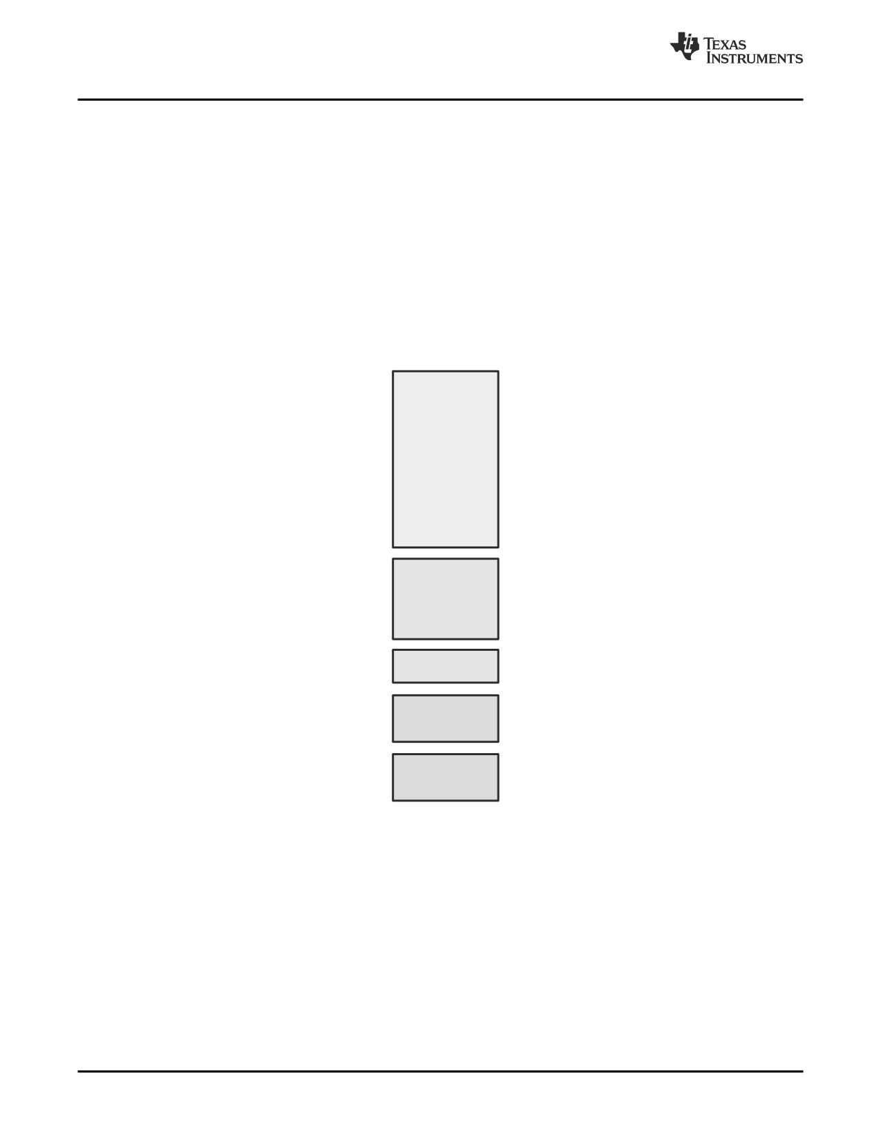
As Figure 2-3 shows, the file in Figure 2-2 creates five sections:
.text
contains 15 32-bit words of object code.
.data
contains six words of initialized data.
vectors
is a named section created with the .sect directive; it contains two words of object code.
.bss
reserves 44 bytes in memory.
newvars
is a named section created with the .usect directive; it contains eight bytes in memory.
The second column shows the object code that is assembled into these sections; the first column shows
the source statements that generated the object code.
Figure 2-3. Object Code Generated by the File in Figure
2-2
Line numbers
Object code
Section
19
00800528
.text
20
021085E0
22
01003664
23
00004000
24
0087E1A0
25
021041E0
26
80000112
27
00008000
29
0200007C-
44
01003664
45
00006000
46
020C4480
47
02800028-
48
02800068-
49
02140274
5
00000011
.data
5
00000022
14
00001234
34
000000AA
34
000000BB
34
000000CC
54
00000000’
vectors
54
00000024’
No data—
.bss
9
44 bytes
10
reserved
No data—
newvars
38
8 bytes
39
reserved
28
Introduction to Object Modules
How the Linker Handles Sections
2.3
How the Linker Handles Sections
The linker has two main functions related to sections. First, the linker uses the sections in object files as
building blocks; it combines input sections (when more than one file is being linked) to create output
sections in an executable output module. Second, the linker chooses memory addresses for the output
sections.
Two linker directives support these functions:
• The MEMORY directive allows you to define the memory map of a target system. You can name
portions of memory and specify their starting addresses and their lengths.
• The SECTIONS directive tells the linker how to combine input sections into output sections and where
to place these output sections in memory.
Subsections allow you to manipulate sections with greater precision. You can specify subsections with the
linker's SECTIONS directive. If you do not specify a subsection explicitly, then the subsection is combined
with the other sections with the same base section name.
It is not always necessary to use linker directives. If you do not use them, the linker uses the target
processor's default allocation algorithm described in Section 7.12. When you do use linker directives, you
must specify them in a linker command file.
Refer to the following sections for more information about linker command files and linker directives:
• Section 7.5, Linker Command Files
• Section 7.7, The MEMORY Directive
• Section 7.8, The SECTIONS Directive
• Section 7.12, Default Allocation Algorithm
2.3.1
Default Memory Allocation
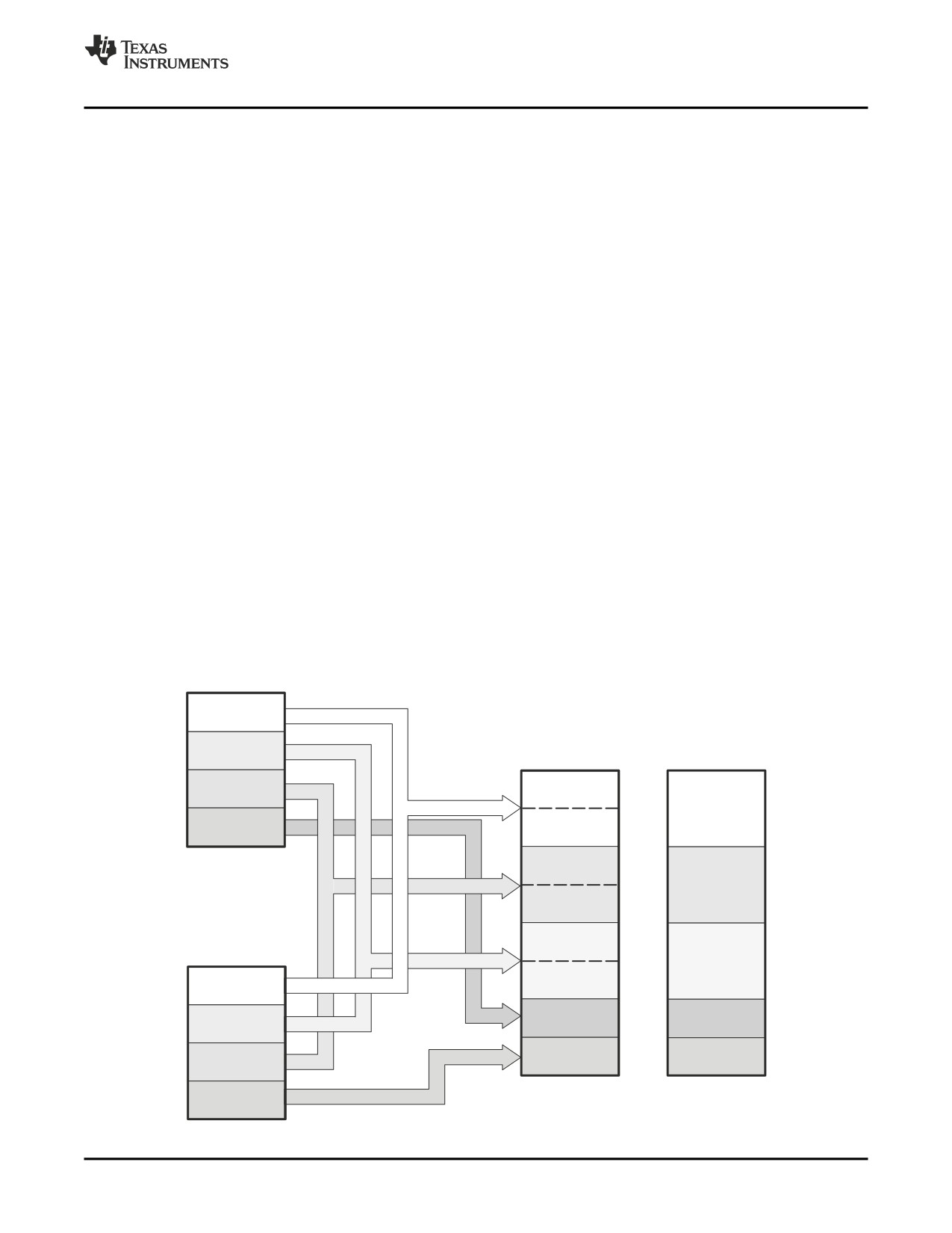
Figure
2-4 illustrates the process of linking two files together.
Figure 2-4. Combining Input Sections to Form an Executable Object Module
file1.obj
.text
.bss
Executable
object module
Memory map
file1
.data
(.text)
Executable
code
Init
file2
(.text)
(named section)
(.text)
file1
(.data)
Initialized
data
file2
(.data)
(.data)
file1
(.bss)
Space for
file2.obj
variables
file2
(.bss)
.text
(.bss)
Init
Init
.bss
.data
Tables
Tables
Tables
(named section)
Introduction to Object Modules
29
Relocation
In Figure 2-4, file1.obj and file2.obj have been assembled to be used as linker input. Each contains the
.text, .data, and .bss default sections; in addition, each contains a named section. The executable object
module shows the combined sections. The linker combines the .text section from file1.obj and the .text
section from file2.obj to form one .text section, then combines the two .data sections and the two .bss
sections, and finally places the named sections at the end. The memory map shows how the sections are
put into memory.
By default, the linker begins at 0h and places the sections one after the other in the following order: .text,
.const, .data, .bss, .cinit, and then any named sections in the order they are encountered in the input files.
The C/C++ compiler uses the .const section to store string constants, and variables or arrays that are
declared as far const. The C/C++ compiler produces tables of data for autoinitializing global variables;
these variables are stored in a named section called .cinit (see Example 7-7). For more information on the
.const and .cinit sections, see the TMS320C6000 Optimizing Compiler User's Guide.
2.3.2
Placing Sections in the Memory Map
Figure 2-4 illustrates the linker's default method for combining sections. Sometimes you may not want to
use the default setup. For example, you may not want all of the .text sections to be combined into a single
.text section. Or you may want a named section placed where the .data section would normally be
allocated. Most memory maps contain various types of memory (RAM, ROM, EPROM, etc.) in varying
amounts; you may want to place a section in a specific type of memory.
For further explanation of section placement within the memory map, see the discussions in Section 7.7
and Section 7.8.
2.4
Relocation
The assembler treats each section as if it began at address 0. All relocatable symbols (labels) are relative
to address 0 in their sections. Of course, all sections cannot actually begin at address 0 in memory, so the
linker relocates sections by:
• Allocating them into the memory map so that they begin at the appropriate address as defined with the
linker's MEMORY directive
• Adjusting symbol values to correspond to the new section addresses
• Adjusting references to relocated symbols to reflect the adjusted symbol values
The linker uses relocation entries to adjust references to symbol values. The assembler creates a
relocation entry each time a relocatable symbol is referenced. The linker then uses these entries to patch
the references after the symbols are relocated. Example 2-1 contains a code segment for a
TMS320C6000 device that generates relocation entries.
Example 2-1. Code That Generates Relocation Entries
1
.global X
2 00000000 00000012! Z:
B
X
; Uses an external relocation
3 00000004 0180082A'
MVKL
Y,B3
; Uses an internal relocation
4 00000008 0180006A'
MVKH
Y,B3
; Uses an internal relocation
5 0000000C 00004000
NOP
3
6
7 00000010 0001E000
Y:
IDLE
8 00000014 00000212
B
Y
9 00000018 00008000
NOP
5
In Example 2-1, both symbols X and Y are relocatable. Y is defined in the .text section of this module; X is
defined in another module. When the code is assembled, X has a value of 0 (the assembler assumes all
undefined external symbols have values of 0), and Y has a value of 16 (relative to address 0 in the .text
section). The assembler generates two relocation entries: one for X and one for Y. The reference to X is
an external reference (indicated by the ! character in the listing). The reference to Y is to an internally
defined relocatable symbol (indicated by the ' character in the listing).
30
Introduction to Object Modules
Relocation
After the code is linked, suppose that X is relocated to address 0x7100. Suppose also that the .text
section is relocated to begin at address 0x7200; Y now has a relocated value of 0x7210. The linker uses
the two relocation entries to patch the two references in the object code:
00000012
B X
becomes
0fffe012
0180082A MVKL Y
becomes
01B9082A
0180006A MVKH Y
becomes
1860006A
Sometimes an expression contains more than one relocatable symbol, or cannot be evaluated at
assembly time. In this case, the assembler encodes the entire expression in the object file. After
determining the addresses of the symbols, the linker computes the value of the expression as shown in
Example 2-2.
Example 2-2. Simple Assembler Listing
1
.global sym1, sym2
2
3 00000000 00800028%
MVKL
sym2 - sym1, A1
The symbols sym1 and sym2 are both externally defined. Therefore, the assembler cannot evaluate the
expression sym2 - sym1, so it encodes the expression in the object file. The '%' listing character indicates
a relocation expression. Suppose the linker relocates sym2 to 300h and sym1 to 200h. Then the linker
computes the value of the expression to be 300h - 200h = 100h. Thus the MVKL instruction is patched to:
00808028
MVKL
100h,A1
Expression Cannot Be Larger Than Space Reserved
Note: If the value of an expression is larger, in bits, than the space reserved for it, you will receive
an error message from the linker.
Each section in a COFF object file has a table of relocation entries. The table contains one relocation
entry for each relocatable reference in the section. The linker usually removes relocation entries after it
uses them. This prevents the output file from being relocated again (if it is relinked or when it is loaded). A
file that contains no relocation entries is an absolute file (all its addresses are absolute addresses). If you
want the linker to retain relocation entries, invoke the linker with the --relocatable option (see
Section 7.4.2.2).
Introduction to Object Modules
31
Run-Time Relocation
2.5
Run-Time Relocation
At times you may want to load code into one area of memory and run it in another. For example, you may
have performance-critical code in an external-memory-based system. The code must be loaded into
external memory, but it would run faster in internal memory.
The linker provides a simple way to handle this. Using the SECTIONS directive, you can optionally direct
the linker to allocate a section twice: first to set its load address and again to set its run address. Use the
load keyword for the load address and the run keyword for the run address.
The load address determines where a loader places the raw data for the section. Any references to the
section (such as references to labels in it) refer to its run address. The application must copy the section
from its load address to its run address before the first reference of the symbol is encountered at run time;
this does not happen automatically simply because you specify a separate run address. For an example
that illustrates how to move a block of code at run time, see Example 7-9.
If you provide only one allocation (either load or run) for a section, the section is allocated only once and
loads and runs at the same address. If you provide both allocations, the section is actually allocated as if it
were two separate sections of the same size.
Uninitialized sections (such as .bss) are not loaded, so the only significant address is the run address. The
linker allocates uninitialized sections only once; if you specify both run and load addresses, the linker
warns you and ignores the load address.
For a complete description of run-time relocation, see Section 7.9.
2.6
Loading a Program
The linker produces executable object modules. An executable object module has the same format as
object files that are used as linker input; the sections in an executable object module, however, are
combined and relocated into target memory.
To run a program, the data in the executable object module must be transferred, or loaded, into target
system memory. Several methods can be used for loading a program, depending on the execution
environment. Common situations are described below:
• Code Composer Studio can load an executable object module into a simulator or onto hardware. The
Code Composer Studio loader reads the executable file and copies the program into target memory.
• You can use the hex conversion utility (hex6x, which is shipped as part of the assembly language
package) to convert the executable object module into one of several object file formats. You can then
use the converted file with an EPROM programmer to burn the program into an EPROM.
32
Introduction to Object Modules
Symbols in an Object File
2.7
Symbols in an Object File
An object file contains a symbol table that stores information about symbols in the program. The linker
uses this table when it performs relocation.
2.7.1
External Symbols
External symbols are symbols that are defined in one file and referenced in another file. You can use the
.def, .ref, or .global directive to identify symbols as external:
.def
The symbol is defined in the current file and used in another file.
.ref
The symbol is referenced in the current file, but defined in another file.
.global
The symbol can be either of the above.
The following code segment illustrates these definitions.
.def
x
.ref
y
.global z
.global q
q: B
B3
NOP
4
MVK
1, B1
x: MV
A0,A1
MVKL
y,B3
MVKH
y,B3
B
z
NOP
5
In this example, the .def definition of x says that it is an external symbol defined in this file and that other
files can reference x. The .ref definition of y says that it is an undefined symbol that is defined in another
file. The .global definition of z says that it is defined in some file and available in this file. The .global
definition of q says that it is defined in this file and that other files can reference q.
The assembler places x, y, z, and q in the object file's symbol table. When the file is linked with other
object files, the entries for x and q resolve references to x and q in other files. The entries for y and z
cause the linker to look through the symbol tables of other files for y's and z's definitions.
The linker must match all references with corresponding definitions. If the linker cannot find a symbol's
definition, it prints an error message about the unresolved reference. This type of error prevents the linker
from creating an executable object module.
2.7.2
The Symbol Table
The assembler always generates an entry in the symbol table when it encounters an external symbol
(both definitions and references defined by one of the directives in Section 2.7.1). The assembler also
creates special symbols that point to the beginning of each section; the linker uses these symbols to
relocate references to other symbols.
The assembler does not usually create symbol table entries for any symbols other than those described
above, because the linker does not use them. For example, labels are not included in the symbol table
unless they are declared with the .global directive. For informational purposes, it is sometimes useful to
have entries in the symbol table for each symbol in a program. To accomplish this, invoke the assembler
with the --output_all_syms option (see Section 3.3).
Introduction to Object Modules
33
34
Introduction to Object Modules
Chapter 3
Assembler Description
The TMS320C6000™ assembler translates assembly language source files into machine language object
files. These files are in object modules, which are discussed in Chapter 2. Source files can contain the
following assembly language elements:
Assembler directives
described in Chapter 4
Macro directives
described in Chapter 5
Assembly language instructions
described in the TMS320C6000 CPU and Instruction
Set Reference Guide
Topic
Page
3.1
Assembler Overview
36
3.2
The Assembler's Role in the Software Development Flow
37
3.3
Invoking the Assembler
38
3.4
Naming Alternate Directories for Assembler Input
39
3.5
Source Statement Format
41
3.6
Constants
44
3.7
Character Strings
46
3.8
Symbols
46
3.9
Expressions
52
3.10
Source Listings
55
3.11
Debugging Assembly Source
57
3.12
Cross-Reference Listings
58
Assembler Description
35
Assembler Overview
3.1
Assembler Overview
The 2-pass assembler does the following:
• Processes the source statements in a text file to produce a relocatable object file
• Produces a source listing (if requested) and provides you with control over this listing
• Allows you to segment your code into sections and maintain a section program counter (SPC) for each
section of object code
• Defines and references global symbols and appends a cross-reference listing to the source listing (if
requested)
• Allows conditional assembly
• Supports macros, allowing you to define macros inline or in a library
36
Assembler Description
The Assembler's Role in the Software Development Flow
3.2
The Assembler's Role in the Software Development Flow
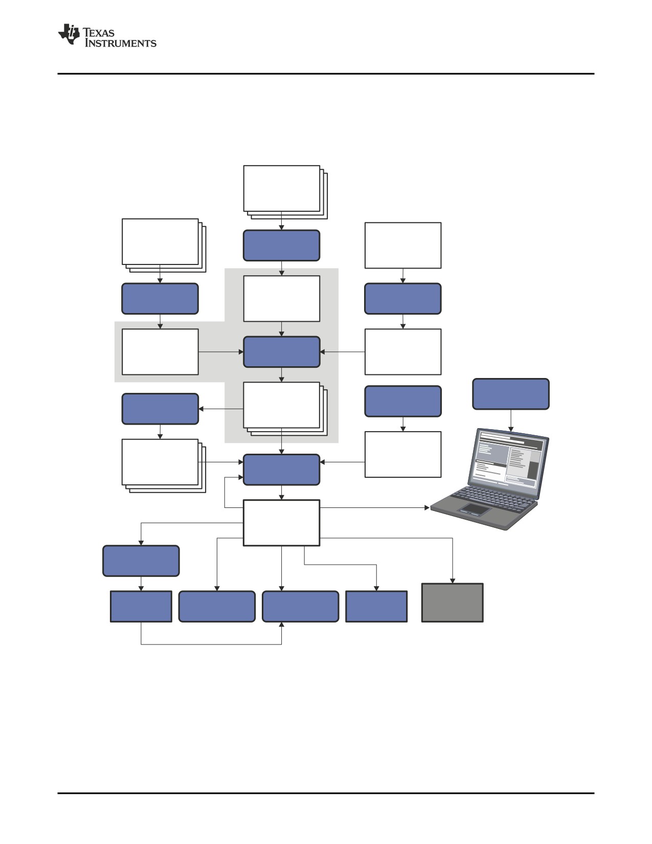
Figure 3-1 illustrates the assembler's role in the software development flow. The shaded portion highlights
the most common assembler development path. The assembler accepts assembly language source files
as input, both those you create and those created by the TMS320C6000 C/C++ compiler.
Figure 3-1. The Assembler in the TMS320C6000 Software Development Flow
C/C++
source
files
Macro
source
C/C++
Linear
files
compiler
assembly
Assembler
Assembly
Archiver
source
optimizer
Assembly
Macro
Assembler
optimized
library
file
Debugging
Library-build
Object
tools
process
Archiver
files
Run-time-
Library of
support
object
library
Linker
files
Executable
object file
Hex-conversion
utility
EPROM
Cross-reference
Object file
C6000
Absolute lister
programmer
lister
utilities
Assembler Description
37
Invoking the Assembler
3.3
Invoking the Assembler
To invoke the assembler, enter the following:
cl6x input file [options]
cl6x
is the command that invokes the assembler through the compiler. The compiler considers
any file with an .asm extension to be an assembly file and calls the assembler.
input file
names the assembly language source file.
options
identify the assembler options that you want to use. Options are not case sensitive and can
appear anywhere on the command line following the command. Precede each option with a
hyphen.
The valid assembler options are listed in Table 3-1:
Table 3-1. TMS320C6000 Assembler Options
Option
Alias
Description
--absolute_listing
-aa
creates an absolute listing. When you use --absolute_listing, the assembler does not
produce an object file. The --absolute_listing option is used in conjunction with the absolute
lister.
--asm_define=name[=def]
-ad
sets the name symbol. This is equivalent to inserting name .set [value] at the beginning of
the assembly file. If value is omitted, the symbol is set to 1. See Section 3.8.4.
--asm_dependency
-apd
performs preprocessing for assembly files, but instead of writing preprocessed output,
writes a list of dependency lines suitable for input to a standard make utility. The list is
written to a file with the same name as the source file but with a .ppa extension.
--asm_includes
-api
performs preprocessing for assembly files, but instead of writing preprocessed output,
writes a list of files included with the .include directive. The list is written to a file with the
same name as the source file but with a .ppa extension.
--asm_listing
-al
produces a listing file with the same name as the input file with a .lst extension.
--asm_undefine= name
-au
undefines the predefined constant name, which overrides any --asm_define options for the
specified constant.
--big_endian
-me
produces object code in big-endian format.
--cmd_file= filename
-@
appends the contents of a file to the command line. You can use this option to avoid
limitations on command line length imposed by the host operating system. Use an asterisk
or a semicolon (* or ;) at the beginning of a line in the command file to include comments.
Comments that begin in any other column must begin with a semicolon. Within the
command file, filenames or option parameters containing embedded spaces or hyphens
must be surrounded with quotation marks. For example: "this-file.asm"
--copy_file= filename
-ahc
copies the specified file for the assembly module. The file is inserted before source file
statements. The copied file appears in the assembly listing files.
--cross_reference
-ax
produces a cross-reference table and appends it to the end of the listing file; it also adds
cross-reference information to the object file for use by the cross-reference utility. If you do
not request a listing file but use the --cross_reference option, the assembler creates a
listing file automatically, naming it with the same name as the input file with a .lst extension.
--include_file= filename
-ahi
includes the specified file for the assembly module. The file is included before source file
statements. The included file does not appear in the assembly listing files.
--include_path= pathname
-I
specifies a directory where the assembler can find files named by the .copy, .include, or
.mlib directives. There is no limit to the number of directories you can specify in this
manner; each pathname must be preceded by the --include_path option. See Section 3.4.1.
--machine_regs
displays reg operands as machine registers in the assembly file for debugging purposes.
--no_compress
prevents compression (C6400+ and C6740). Fetch packets that utilize 16-bit instructions
are not created.
--no_reload_errors
turns off all reload-related loop buffer error messages (C6400+ and C6740).
--output_all_syms
-as
puts all defined symbols in the object file's symbol table. The assembler usually puts only
global symbols into the symbol table. When you use --output_all_syms, symbols defined as
labels or as assembly-time constants are also placed in the table.
--silicon_version= n
-mv
selects the target CPU version using the last four digits of the TMS320C6000 part number.
38
Assembler Description
Naming Alternate Directories for Assembler Input
Table 3-1. TMS320C6000 Assembler Options (continued)
Option
Alias
Description
--symdebug:dwarf
-g
enables assembler source debugging in the C source debugger. Line information is output
to the object module for every line of source in the assembly language source file. You
cannot use the --symdebug:dwarf option on assembly code that contains .line directives.
See Section 3.11.
--syms_ignore_case
-ac
makes case insignificant in the assembly language files. For example, --syms_ignore_case
makes the symbols ABC and abc equivalent. If you do not use this option, case is
significant (default). Case significance is enforced primarily with symbol names, not with
mnemonics and register names.
For more information about the --big_endian and --silicon_version options, see the TMS320C6000
Optimizing Compiler User's Guide.
3.4
Naming Alternate Directories for Assembler Input
The .copy, .include, and .mlib directives tell the assembler to use code from external files. The .copy and
.include directives tell the assembler to read source statements from another file, and the .mlib directive
names a library that contains macro functions. Chapter 4 contains examples of the .copy, .include, and
.mlib directives. The syntax for these directives is:
.copy ["]filename["]
.include ["]filename["]
.mlib ["]filename["]
The filename names a copy/include file that the assembler reads statements from or a macro library that
contains macro definitions. If filename begins with a number the double quotes are required. The filename
may be a complete pathname, a partial pathname, or a filename with no path information. The assembler
searches for the file in the following locations in the order given:
1. The directory that contains the current source file. The current source file is the file being assembled
when the .copy, .include, or .mlib directive is encountered.
2. Any directories named with the --include_path option
3. Any directories named with the C6X_A_DIR environment variable
4. Any directories named with the C6X_C_DIR environment variable
Because of this search hierarchy, you can augment the assembler's directory search algorithm by using
the --include_path option (described in Section 3.4.1) or the C6X_A_DIR environment variable (described
in Section 3.4.2). C6X_C_DIR is discussed in the TMS320C6000 Optimizing Compiler User's Guide.
3.4.1
Using the --include_path Assembler Option
The --include_path assembler option names an alternate directory that contains copy/include files or
macro libraries. The format of the --include_path option is as follows:
cl6x --include_path=pathname source filename [other options]
There is no limit to the number of --include_path options per invocation; each --include_path option names
one pathname. In assembly source, you can use the .copy, .include, or .mlib directive without specifying
path information. If the assembler does not find the file in the directory that contains the current source
file, it searches the paths designated by the --include_path options.
For example, assume that a file called source.asm is in the current directory; source.asm contains the
following directive statement:
.copy "copy.asm"
Assume the following paths for the copy.asm file:
Assembler Description
39
Naming Alternate Directories for Assembler Input
UNIX:
/tools/files/copy.asm
Windows:
c:\tools\files\copy.asm
You could set up the search path with the commands shown below:
Operating System
Enter
UNIX (Bourne shell)
cl6x --include_path=/tools/files source.asm
Windows
cl6x
--include_path=c:\tools\files source.asm
The assembler first searches for copy.asm in the current directory because source.asm is in the current
directory. Then the assembler searches in the directory named with the --include_path option.
3.4.2
Using the C6X_A_DIR Environment Variable
An environment variable is a system symbol that you define and assign a string to. The assembler uses
the C6X_A_DIR environment variable to name alternate directories that contain copy/include files or
macro libraries.
The assembler looks for the C6X_A_DIR environment variable and then reads and processes it. If the
assembler does not find the C6X_A_DIR variable, it then searches for C6X_C_DIR. The
processor-specific variables are useful when you are using Texas Instruments tools for different
processors at the same time.
See the TMS320C6000 Optimizing Compiler User's Guide for details on C6X_C_DIR.
The command syntax for assigning the environment variable is as follows:
Operating System
Enter
UNIX (Bourne Shell)
C6X_A_DIR="pathname1;pathname2; . . . "; export C6X_A_DIR
Windows
set C6X_A_DIR=pathname1;pathname2; . . .
The pathnames are directories that contain copy/include files or macro libraries. The pathnames must
follow these constraints:
• Pathnames must be separated with a semicolon.
• Spaces or tabs at the beginning or end of a path are ignored. For example the space before and after
the semicolon in the following is ignored:
set C6X_A_DIR= c:\path\one\to\tools ; c:\path\two\to\tools
• Spaces and tabs are allowed within paths to accommodate Windows directories that contain spaces.
For example, the pathnames in the following are valid:
set C6X_A_DIR=c:\first path\to\tools;d:\second path\to\tools
In assembly source, you can use the .copy, .include, or .mlib directive without specifying path information.
If the assembler does not find the file in the directory that contains the current source file or in directories
named by the --include_path option, it searches the paths named by the environment variable.
For example, assume that a file called source.asm contains these statements:
.copy "copy1.asm"
.copy "copy2.asm"
Assume the following paths for the files:
UNIX:
/tools/files/copy1.asm and /dsys/copy2.asm
Windows:
c:\tools\files\copy1.asm and c:\dsys\copy2.asm
40
Assembler Description
Source Statement Format
You could set up the search path with the commands shown below:
Operating System
Enter
UNIX (Bourne shell)
C6X_A_DIR="/dsys"; export C6X_A_DIR
cl6x
--include_path=/tools/files source.asm
Windows
set C6X_A_DIR=c:\dsys
cl6x
--include_path=c:\tools\files source.asm
The assembler first searches for copy1.asm and copy2.asm in the current directory because source.asm
is in the current directory. Then the assembler searches in the directory named with the --include_path
option and finds copy1.asm. Finally, the assembler searches the directory named with C6X_A_DIR and
finds copy2.asm.
The environment variable remains set until you reboot the system or reset the variable by entering one of
these commands:
Operating System
Enter
UNIX (Bourne shell)
set C6X_A_DIR=
Windows
unset C6X_A_DIR
3.5
Source Statement Format
TMS320C6000 assembly language source programs consist of source statements that can contain
assembler directives, assembly language instructions, macro directives, and comments. A source
statement can contain five ordered fields (label, mnemonic, unit specifier, operand list, and comment). The
general syntax for source statements is as follows:
[label[:]] [||] [[register]] mnemonic [unit specifier] [operand list][;comment]
Labels cannot be placed on instructions that have parallel bars.
Following are examples of source statements:
two
.set
2
; Symbol Two = 2
Label:
MVK
two,A2 ; Move 2 into register A2
.word 016h
; Initialize a word with 016h
The C6000 assembler reads up to 200 characters per line. Any characters beyond 200 are truncated.
Keep the operational part of your source statements (that is, everything other than comments) less than
200 characters in length for correct assembly. Your comments can extend beyond the 200-character limit,
but the truncated portion is not included in the listing file.
Follow these guidelines:
• All statements must begin with a label, a blank, an asterisk, or a semicolon.
• Labels are optional; if used, they must begin in column 1.
• One or more blanks must separate each field. Tab and space characters are blanks. You must
separate the operand list from the preceding field with a blank.
• Comments are optional. Comments that begin in column 1 can begin with an asterisk or a semicolon (*
or ;), but comments that begin in any other column must begin with a semicolon.
• In a conditional instruction, the condition register must be surrounded by square brackets.
• The functional unit specifier is optional. If you do not specify the functional unit, the assembler assigns
a legal functional unit based on the mnemonic field.
• A mnemonic cannot begin in column 1 or it will be interpreted as a label.
The following sections describe each of the fields.
Assembler Description
41
Source Statement Format
3.5.1
Label Field
Labels are optional for all assembly language instructions and for most (but not all) assembler directives.
When used, a label must begin in column 1 of a source statement. A label can contain up to 128
alphanumeric characters (A-Z, a-z, 0-9, _, and $). Labels are case sensitive (except when the
--syms_ignore_case option is used), and the first character cannot be a number. A label can be followed
by a colon (:). The colon is not treated as part of the label name. If you do not use a label, the first
character position must contain a blank, a semicolon, or an asterisk. You cannot use a label with an
instruction that is in parallel with a previous instruction.
When you use a label, its value is the current value of the SPC. The label points to the statement it is
associated with. For example, if you use the .word directive to initialize several words, a label points to the
first word. In the following example, the label Start has the value 40h.
9
* Assume some code was assembled
10 00000040 0000000A Start:
.word 0Ah,3,7
00000044 00000003
00000048 00000007
A label on a line by itself is a valid statement. The label assigns the current value of the section program
counter to the label; this is equivalent to the following directive statement:
label .equ
$
; $ provides the current value of the SPC
When a label appears on a line by itself, it points to the instruction on the next line (the SPC is not
incremented):
1 00000000
Here:
2 00000000 00000003
.word 3
If you do not use a label, the character in column 1 must be a blank, an asterisk, or a semicolon.
3.5.2
Mnemonic Field
The mnemonic field follows the label field. The mnemonic field cannot start in column 1; if it does, it is
interpreted as a label. There is one exception: the parallel bars (||) of the mnemonic field can start in
column 1. The mnemonic field can begin with one of the following items:
• Pipe symbols (||) indicate instructions that are in parallel with a previous instruction. You can have up
to eight instructions running in parallel. The following example demonstrates six instructions running in
parallel:
Inst1
||
Inst2
||
Inst3
These five instructions run in
||
Inst4
parallel with the first instruc-
||
Inst5
tion.
||
Inst6
Inst7
• Square brackets ([ ]) indicate conditional instructions. The machine-instruction mnemonic is executed
based on the value of the register within the brackets; valid register names are A0 for C64xx only, A1,
A2, B0, B1, and B2. The instruction is executed if the value of the register is nonzero. If the register
name is preceded by an exclamation point (!), then the instruction is executed if the value of the
register is 0. For example:
[A1] ZERO A2
; If A1 is not equal to zero, A2 = 0
Next, the mnemonic field contains one of the following items:
• Machine-instruction mnemonic (such as ADDK, MVKH, B)
• Assembler directive (such as .data, .list, .equ)
• Macro directive (such as .macro, .var, .mexit)
• Macro call
42
Assembler Description
///////////////////////////////////////