High Level Assembler for z/OS & z/VM & z/VSE. Language Reference (Version 1 Release 6) - page 12
The MNOTE instruction can be used inside macro definitions or in open code, and
its operation code can be created by substitution. The MNOTE instruction causes
the generation of a message that is given a statement number in the printed listing.
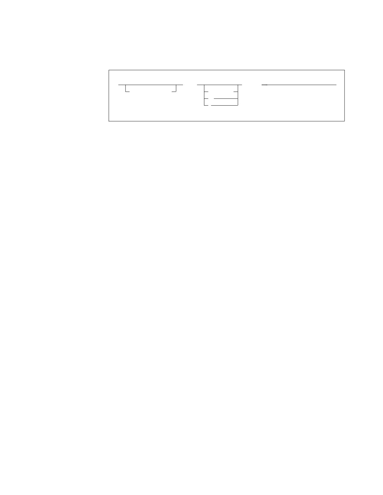
►►
MNOTE
message
►◄
sequence_symbol
severity,
*,
,
sequence_symbol
Is a sequence symbol.
severity
Is a severity code. The severity operand can be any decimal self-defining term,
or a SETA variable symbol. The term must have a value in the range 0 through
255. The severity code is used to determine the return code issued by the
assembler when it returns control to the operating system. The severity can
also change the value of the system variable symbols &SYSM_HSEV and
&SYSM_SEV (see “&SYSM_HSEV System Variable Symbol” on page 279 and
“&SYSM_SEV System Variable Symbol” on page 279).
message
Is the message text. It can be any combination of characters enclosed in
apostrophes. The rules that apply to this character string are as follows:
v Variable symbols are allowed. The apostrophes that enclose the message can
be generated from variable symbols.
v Two ampersands or two apostrophes are needed to generate an ampersand
or an apostrophe. If variable symbols have ampersands or apostrophes as
values, the values must be coded as two ampersands or two apostrophes.
v If the number of characters in the character string plus the rest of the
MNOTE operand exceeds 1024 bytes the assembler issues diagnostic
message
ASMA062E Illegal operand format
Note: The maximum length of the second operand is 1020.
v Double-byte data is permissible in the operand field when the DBCS
assembler option is specified. The double-byte data must be valid.
v The DBCS ampersand and apostrophe are not recognized as delimiters.
v A double-byte character that contains the value of an EBCDIC ampersand or
apostrophe in either byte is not recognized as a delimiter when enclosed by
SO and SI.
Any remarks for the MNOTE instruction statement must be separated by one or
more spaces from the apostrophe that ends the message.
If severity is provided, or severity is omitted but the comma separating it from
message is present, the message is treated as an error message; otherwise the
message is treated as comments. The rules for specifying the contents of severity
are:
v The severity code can be specified as any arithmetic expression allowed in the
operand field of a SETA instruction. The expression must have a value in the
range 0 through 255.
Chapter 5. Assembler instruction statements
201
Example:
MNOTE 2,’ERROR IN SYNTAX’
The generated result is:
2,ERROR IN SYNTAX
v
If the severity code is omitted, but the comma separating it from the message is
present, the assembler assigns a default value of 1 as the severity code.
Example:
MNOTE ,’ERROR, SEV 1’
The generated result is:
,ERROR, SEV 1
v
An asterisk in the severity code subfield causes the message and the asterisk to
be generated as a comment statement.
Example:
MNOTE *,’NO ERROR’
The generated result is:
*,NO ERROR
Here is an example taken from a CICS® macro:
MNOTE 8,’FIELD IS DEFINED OUTSIDE OF THE SIZE OPERAND’
MNOTE *,’PARAMETERS SPECIFIED IN THE DFHMDI MACRO,’
MNOTE *,’MACRO REQUEST IS IGNORED.’
A further advantage of this approach is that only one severity 8 error is seen
instead of three.
v
If the severity code subfield is omitted, including the comma separating it from
the message, the assembler generates the message as a comment statement.
Example:
MNOTE ’NO ERROR’
The generated result is:
NO ERROR
Notes:
1. An MNOTE instruction causes a message to be printed, if the current PRINT
option is ON, even if the PRINT NOGEN option is specified.
2. The statement number of the message generated from an MNOTE instruction
with a severity code is listed among any other error messages for the current
source module. However, the message is printed only if the severity code
specified is greater than or equal to the severity code nnn specified in the
FLAG(nnn) assembler option.
3. The statement number of the comments generated from an MNOTE instruction
without a severity code is not listed among error messages.
OPSYN instruction
The OPSYN instruction defines or deletes symbolic operation codes.
The OPSYN instruction has two formats. The first format defines a new operation
code to represent an existing operation code, or to redefine an existing operation
code for:
v Machine and extended mnemonic instructions
v Assembler instructions, including conditional assembly instructions
v Macro instructions
202
HLASM V1R6 Language Reference

Define operation code
►►
symbol
OPSYN operation_code_2
►◄
operation_code_1
If operation_code_2 has been previously defined as both a machine instruction and
as a macro, both are copied to the definition of operation_code_1.
The second format deletes an existing operation code for:
v Machine and extended mnemonic instructions
v Assembler instructions, including conditional assembly instructions
v Macro instructions
Delete operation code
►► operation_code_1
OPSYN
►◄
symbol
Is one of the following:
v An ordinary symbol that is not the same as an existing operation code
v A variable symbol that has been assigned a character string with a value that
is valid for an ordinary symbol and is not the same as an existing operation
code
operation_code_1
Is one of the following:
v An operation code described in this chapter
v Any machine instruction (such as those described in Chapter 4, “Machine
instruction statements,” on page 75 or Chapter 9, “How to write conditional
assembly instructions,” on page 319)
v The operation code defined by a previous OPSYN instruction
v The name of a previously defined macro.
operation_code_2
Is one of these:
v An operation code described in this chapter
v Any machine instruction (such as those described in Chapter 4, “Machine
instruction statements,” on page 75 or Chapter 9, “How to write conditional
assembly instructions,” on page 319)
v The operation code defined by a previous OPSYN instruction
v The name of a previously defined macro.
In the first format, the OPSYN instruction assigns the properties of the operation
code denoted by operation_code_2 to the ordinary symbol denoted by symbol or the
operation code denoted by operation_code_1.
Chapter 5. Assembler instruction statements
203
In the second format, the OPSYN instruction causes the operation code specified in
operation_code_1 to lose its properties as an operation code.
The OPSYN instruction can be coded anywhere in the program to redefine an
operation code, following an ICTL instruction, if any.
The symbol in the name field can represent a valid operation code. It loses its
current properties as if it had been defined in an OPSYN instruction with a
space-filled operand field. In the following example, L and LR both possess the
properties of the LR machine instruction operation code:
L
OPSYN
LR
When the same symbol appears in the name field of two OPSYN instructions, the
latest definition takes precedence. In this example, STORE now represents the STH
machine operation:
STORE
OPSYN
ST
STORE
OPSYN
STH
Note: OPSYN is not processed during lookahead mode (see “Lookahead” on page
340). Therefore it cannot be used during lookahead to replace an opcode that must
be processed during lookahead, such as COPY. For example, assuming AFTER is
defined in COPYBOOK, the following code gives an ASMA042E error (Length
attribute of symbol is unavailable):
AIF
(L’AFTER LT 2).BEYOND
OPCOPY OPSYN COPY
OPSYN not processed during look ahead
OPCOPY COPYBOOK
OPCOPY fails
.BEYOND ANOP ,
Redefining conditional assembly instructions
A redefinition of a conditional assembly instruction only comes into effect in macro
definitions occurring after the OPSYN instruction. The original definition is always
used when a macro instruction calls a macro that was defined and edited before
the OPSYN instruction.
An OPSYN instruction that redefines the operation code of an assembler or
machine instruction generated from a macro instruction is, however, effective
immediately, even if the definition of the macro was made prior to the OPSYN
instruction. Consider the following example:
MACRO
Macro header
MAC
Macro prototype
AIF
MVC
MEND
Macro trailer
AIF
OPSYN
AGO
Assign AGO properties to AIF
MVC
OPSYN
MVI
Assign MVI properties to MVC
MAC
Macro call
(AIF interpreted as AIF instruct-
ion; generated AIFs not printed)
+
MVC
Interpreted as MVI instruction
Open code started at this point
AIF
Interpreted as AGO instruction
MVC
Interpreted as MVI instruction
204
HLASM V1R6 Language Reference

In this example, AIF and MVC instructions are used in a macro definition. AIF is a
conditional assembly instruction, and MVC is a machine instruction. OPSYN
instructions are used to assign the properties of AGO to AIF and to assign the
properties of MVI to MVC. In subsequent calls of the macro MAC, AIF is still
defined, and used, as an AIF operation, but the generated MVC is treated as an
MVI operation. In open code following the macro call, the operations of both
instructions are derived from their new definitions assigned by the OPSYN
instructions. If the macro is redefined (by another macro definition), the new
definitions of AIF and MVC (that is, AGO and MVI) are used for further
generations.
ORG instruction
The ORG instruction alters the setting of the location counter and thus controls the
structure of the current control section. This redefines portions of a control section.
If a control section has not been previously established, ORG initiates an unnamed
(private) control section.
►►
ORG
►◄
symbol
expression
, boundary
,offset
, offset
symbol
Is one of the following:
v An ordinary symbol
v A variable symbol that has been assigned a character string with a value that
is valid for an ordinary symbol
v A sequence symbol
If symbol denotes an ordinary symbol, the ordinary symbol is defined with the
value that the location counter had before the ORG statement is processed.
expression
Is a relocatable expression, the value of which is used to set the location
counter. If expression is omitted, the location counter is set to the next available
location for the current control section.
boundary
Is an absolute expression that must be a number that is a power of 2 with a
range from 2 (halfword) to 4096 (page). If boundary exceeds the SECTALGN
value, message ASMA500W is issued. This message is not issued if the section
being processed is a Reference Control Section (DSECT, DXD, or COM).
boundary must be a predefined absolute expression whose value is known at
the time the ORG statement is processed.
If the boundary operand is greater than 16, the GOFF option must be specified
in addition to the SECTALGN option.
offset
Any absolute expression
Chapter 5. Assembler instruction statements
205
The resultant location counter is calculated as follows:
1. Evaluate expression.
2. If boundary is specified, round the result to the next multiple of boundary.
3. If offset is specified, adjust the result by adding offset.
ORG emits no “fill” bytes for bytes skipped in any direction.
In general, symbols used in expression need not have been previously defined.
However, the relocatable component of expression (that is, the unpaired relocatable
term) must have been previously defined in the same control section in which the
ORG statement appears, or be equated to a previously defined value.
A length attribute reference to the name of an ORG instruction is always invalid.
Message ASMS042E is issued, and a default value of 1 is assigned.
An ORG statement cannot be used to specify a location below the beginning of the
control section in which it appears. For example, the following statement is not
correct if it appears less than 500 bytes from the beginning of the current control
section.
ORG
*-500
This is because the expression specified is negative, and sets the location counter to
a value larger than the assembler can process. The location counter wraps around
(the location counter is discussed in detail in “Location counter” on page 36).
If you specify multiple location counters with the LOCTR instruction, the ORG
instruction can alter only the location counter in use when the instruction appears.
Thus, you cannot control the structure of the whole control section using ORG, but
only the part that is controlled by the current location counter.
An ORG statement cannot be used to change sections or LOCTR segments. For
example:
AA
CSECT
X
DS
D
Y
DS
F
BB
CSECT
ORG
Y
is invalid, because the section containing the ORG statement (BB) is not the same
as the section in AA in which the ORG operand expression Y is defined.
With the ORG statement, you can give two instructions the same location counter
values. In such a case, the second instruction does not always eliminate the effects
of the first instruction. Consider the following example:
ADDR
DC
A(ADDR)
ORG
*-4
B
DC
C’BETA’
In this example, the value of B (’BETA’) is destroyed by the relocation of ADDR
during linkage editing.
The following example shows some examples of ORG using the boundary and
offset operands:
origin csect
ds
235x
Define 235 bytes
org
origin,,3
Move location counter back to start + 3
206
HLASM V1R6 Language Reference
org
*,8
Align on 8 byte boundary
org
*,8,-2
Align to 8 byte boundary -2 bytes
translate dc cl256’ ’
Define aligned translate table
org translate+c’a’
dc
c’ABCDEFGHI’
org
translate+c’j’
dc
c’JKLMNOPQR’
org
translate+c’s’
dc
c’STUVWXYZ’
org
translate+c’A’
dc
c’ABCDEFGHI’
org
translate+c’J’
dc
c’JKLMNOPQR’
org
translate+c’S’
dc
c’STUVWXYZ’
org
,
end
Using Figure 28 on page 208 as an example, to build a translate table (for example,
to convert EBCDIC character code into some other internal code):
1. Define the table (see ▌1▐ in Figure 28 on page 208) as being filled with zeros.
2. Use the ORG instruction to alter the location counter so that its counter value
indicates a specific location (see ▌2▐ in Figure 28 on page 208) within the table.
3. Redefine the data (see ▌3▐ in Figure 28 on page 208) to be assembled into that
location.
4. After repeating the first three steps (see ▌4▐ in Figure 28 on page 208) until
your translate table is complete, use an ORG instruction with a null operand
field to alter the location counter. The counter value then indicates the next
available location (see ▌5▐ in Figure 28 on page 208) in the current control
section (after the end of the translate table).
Both the assembled object code for the whole table filled with zeros, and the object
code for the portions of the table you redefined, are printed in the program
listings. However, the data defined later is loaded over the previously defined
zeros and becomes part of your object program, instead of the zeros.
That is, the ORG instruction can cause the location counter to be set to any part of
a control section, even the middle of an instruction, into which you can assemble
data. It can also cause the location counter to be set to the next available location
so that your program can be assembled sequentially.
Chapter 5. Assembler instruction statements
207

Source Module
│
Object Code
─────────────────────────────────────────────────────┼────────────────────────
│
FIRST
START
0
│
│
│
▌1▐
TABLE
DC
XL256’0’
│ TABLE
(in Hex)
▌2▐
ORG
TABLE+0
│ +0
┌────┐
┌
DC
C’0’
▌3▐
│
│ F0 │
│
DC
C’1’
│
│ F1 │
│
│
│ .
│
│
│
│ .
│
│
ORG
TABLE+13
│ +13
│ .
│
│
DC
C’D’
│
│ C4 │
│
DC
C’E’
│
│ C5 │
│
│
│ .
│
│
│
│ .
│
▌4▐
─┤
ORG
TABLE+C’D’
│
│ .
│
│
DC
AL1(13)
│ +196
│ 13 │
│
DC
AL1(14)
│
│ 14 │
│
│
│ .
│
│
│
│ .
│
│
ORG
TABLE+C’0’
│ +240
│ .
│
│
DC
AL1(0)
│
│ 00 │
│
DC
AL1(1)
│
│ 01 │
│
│
│
│
└
│ +255
└────┘
ORG
│
▌5▐
GOON
DS
0H
│
⌂
│
TABLE+256
│
TR
INPUT,TABLE
│
│
│
INPUT
DS
CL20
│
│
│
END
│
Figure 28. Building a translate table
POP instruction
The POP instruction restores the PRINT, USING, or ACONTROL status saved by
the most recent PUSH instruction.
,
(1)
▼
►►
POP
PRINT
►◄
sequence_symbol
USING
,NOPRINT
ACONTROL
Notes:
1
Each keyword from this group can be selected only once.
208
HLASM V1R6 Language Reference

sequence_symbol
Is a sequence symbol.
PRINT
Instructs the assembler to restore the PRINT status to the status saved by the
most recent PUSH instruction.
USING
Instructs the assembler to restore the USING status to the status saved by the
most recent PUSH instruction.
ACONTROL
Instructs the assembler to restore the ACONTROL status to the status saved by
the most recent PUSH instruction.
NOPRINT
Instructs the assembler to suppress the printing of the POP statement in which
it is specified.
The POP instruction causes the status of the current PRINT, USING or
ACONTROL instruction to be overridden by the PRINT, USING or ACONTROL
status saved by the last PUSH instruction. For example:
PRINT GEN
Printed macro generated code
DCMAC X,27
Call macro to generate DC
+
DC
X’27’
... Generated statement
PUSH
PRINT
Save PRINT status
PRINT
NOGEN
Suppress macro generated code
DCMAC
X,33
Call macro to generate DC
POP
PRINT
Restore PRINT status
DCMAC
X,42
Call macro to generate DC
+
DC
X’42’
... Generated statement
PRINT instruction
The PRINT instruction controls the amount of detail printed in the listing of
programs.
,
▼
►►
PRINT
operand
►◄
sequence_symbol
sequence_symbol
Is a sequence symbol.
operand
Is an operand from one of the groups of operands described below. If a null
operand is supplied, it is accepted by the assembler with no effect on the other
operands specified. The operands are listed in hierarchic order. The effect, if
any, of one operand on other operands is also described.
Chapter 5. Assembler instruction statements
209

ON
►►
►◄
OFF
ON
Instructs the assembler to print, or resume printing, the source and object section
of the assembler listing.
OFF
Instructs the assembler to stop printing the source and object section of the
assembler listing. A subsequent PRINT ON instruction resumes printing.
When this operand is specified the printing actions requested by the GEN,
DATA, MCALL, and MSOURCE operands do not apply.
GEN
►►
►◄
NOGEN
GEN
Instructs the assembler to print all statements generated by the processing of a
macro. This operand does not apply if PRINT OFF has been specified.
NOGEN
Instructs the assembler not to print statements generated by conditional
assembly or the processing of a macro. This applies to all levels of macro
nesting; no generated code is displayed while PRINT NOGEN is in effect. If
this operand is specified, the DATA operand does not apply to constants that
are generated during macro processing. Also, if this operand is specified, the
MSOURCE operand does not apply. When the PRINT NOGEN instruction is in
effect, the assembler prints one of the following on the same line as the macro
call or model statement:
v The object code for the first instruction generated. The object code includes
the data that is shown under the ADDR1 and ADDR2 columns of the
assembler listing.
v The first eight bytes of generated data from a DC instruction
When the assembler forces alignment of an instruction or data constant, it
generates zeros in the object code and prints the generated object code in the
listing. When you use the PRINT NOGEN instruction the generated zeros are
not printed.
Note: If the next line to print after macro call or model statement is a
diagnostic message, the object code or generated data is not shown in the
assembler listing.
The MNOTE instruction always causes a message to be printed.
210
HLASM V1R6 Language Reference

NODATA
►►
►◄
DATA
NODATA
Instructs the assembler to print only the first eight bytes of the object code of
constants. For object code generated by CNOP instructions, only the first 16
bytes of object code will be printed. This operand does not apply if PRINT
OFF has been specified. If PRINT NOGEN has been specified, this operand
does not apply to constants generated during macro processing.
DATA
Instructs the assembler to print the object code of all constants in full. This
operand does not apply if PRINT OFF has been specified. If PRINT NOGEN
has been specified, this operand does not apply to constants generated during
macro processing.
NOMCALL
►►
►◄
MCALL
NOMCALL
Instructs the assembler to suppress the printing of nested macro call
instructions.
MCALL
Instructs the assembler to print nested macro call instructions, including the
name of the macro definition to be processed and the operands and values
passed to the macro definition. The assembler only prints the operands and
comments up to the size of its internal processing buffer. If this size is
exceeded the macro call instruction is truncated, and the characters ... MORE
are added to the end of the printed macro call. This does not affect the
processing of the macro call.
This operand does not apply if either PRINT OFF or PRINT NOGEN has been
specified.
MSOURCE
►►
►◄
NOMSOURCE
MSOURCE
Instructs the assembler to print the source statements generated during macro
processing, as well as the assembled addresses and generated object code of
the statements. This operand does not apply if either PRINT OFF or PRINT
NOGEN has been specified.
Chapter 5. Assembler instruction statements
211

NOMSOURCE
Instructs the assembler to suppress the printing of source statements generated
during macro processing, without suppressing the printing of the assembled
addresses and generated object code of the statements. This operand does not
apply if either PRINT OFF or PRINT NOGEN has been specified.
UHEAD
►►
►◄
NOUHEAD
UHEAD
Instructs the assembler to print a summary of active USINGs following the
TITLE line on each page of the source and object program section of the
assembler listing. This operand does not apply if PRINT OFF has been
specified.
NOUHEAD
Instructs the assembler not to print a summary of active USINGs.
►►
►◄
NOPRINT
NOPRINT
Instructs the assembler to suppress the printing of the PRINT statement in
which it is specified. The NOPRINT operand must only be specified with one
or more other operands.
The PRINT instruction can be specified any number of times in a source module,
but only those operands specified in the instruction change the current print status.
PRINT options can be generated by macro processing during conditional assembly.
However, at assembly time, all options are in force until the assembler encounters
a new and opposite option in a PRINT instruction.
The PUSH and POP instructions, described in “PUSH instruction” on page 214 and
“POP instruction” on page 208, also influence the PRINT options by saving and
restoring the PRINT status.
You can override the effect of the operands of the PRINT instruction by using the
PCONTROL assembler option. For more information about this option, see the
section “PCONTROL” in the HLASM Programmer's Guide.
Unless the NOPRINT operand is specified, or the assembler listing is suppressed
by the NOLIST assembler option, the PRINT instruction itself is printed.
Process statement
The process statement is described under “*PROCESS statement” on page 102.
212
HLASM V1R6 Language Reference
PUNCH instruction
The PUNCH instruction creates a record containing a source or other statement, or
an object record, to be written to the object file.
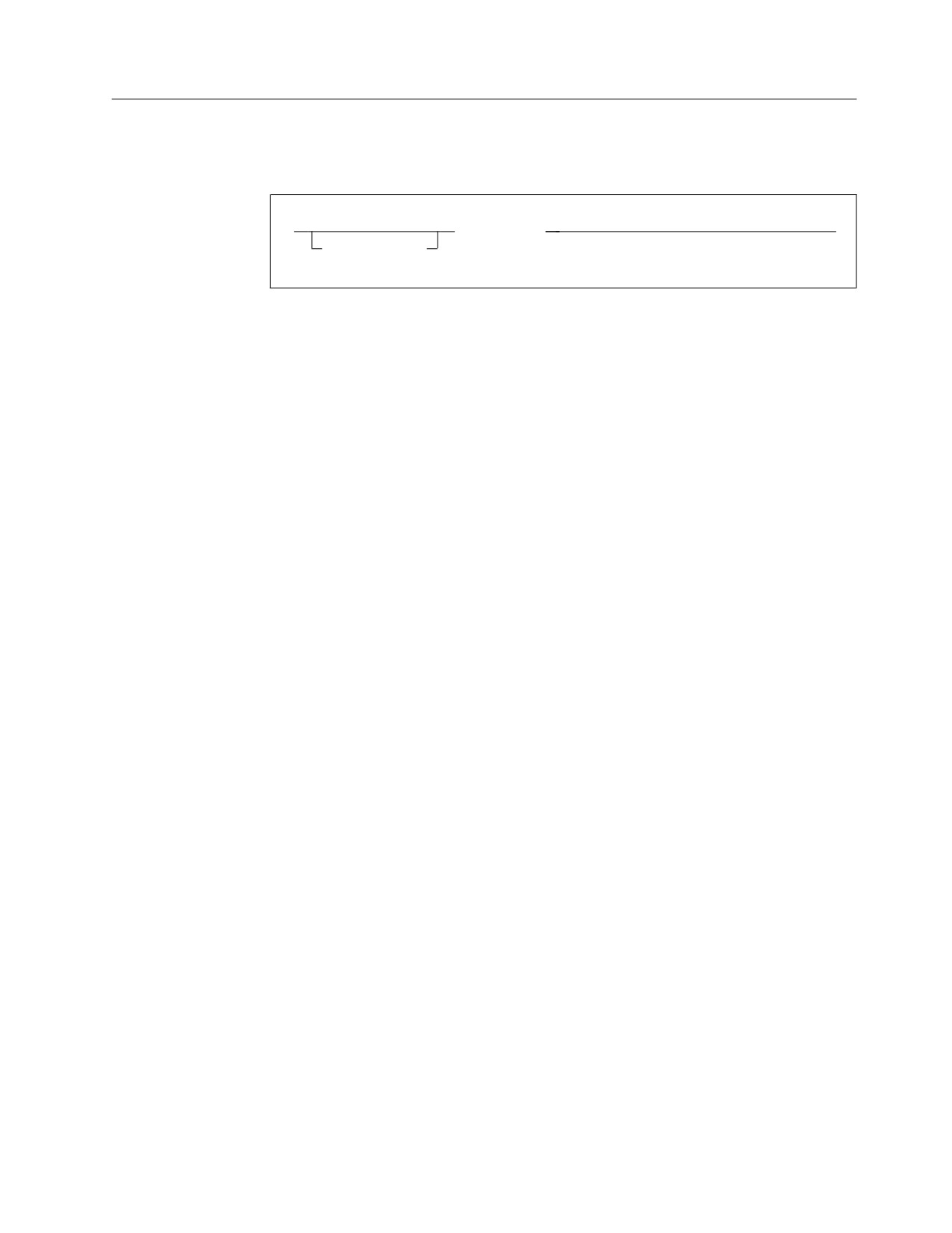
►►
PUNCH string
►◄
sequence_symbol
sequence_symbol
Is a sequence symbol.
string
Is a character string of up to 80 characters, enclosed in apostrophes. All 256
characters in the EBCDIC character set are allowed in the character string.
Variable symbols are also allowed.
Double-byte data is permissible in the operand field when the DBCS assembler
option is specified. However, the following rules apply to double-byte data:
v The DBCS ampersand and the apostrophe are not recognized as delimiters.
v A double-byte character that contains the value of an EBCDIC ampersand or
an apostrophe in either byte is not recognized as a delimiter when enclosed
by SO and SI.
The position of each character specified in the PUNCH statement corresponds
to a column in the record to be punched. However, the following rules apply
to ampersands and apostrophes:
v A single ampersand initiates an attempt to identify a variable symbol and to
substitute its current value.
v A pair of ampersands is punched as one ampersand.
v A pair of apostrophes is punched as one apostrophe.
v An unpaired apostrophe followed by one or more spaces ends the string of
characters punched. If a non-space character follows an unpaired
apostrophe, an error message is issued and nothing is punched.
Only the characters punched, including spaces, count toward the maximum of
80 allowed.
The PUNCH instruction causes the data in its operand to be punched (copied) into
a record. One PUNCH instruction produces one record, but as many PUNCH
instructions as necessary can be used.
You can code PUNCH statements in:
v A source module to produce control statements for the linker. The linker uses
these control statements to process the object module.
v Macro definitions to produce, for example, source statements in other computer
languages or for other processing phases.
The assembler writes the record produced by a PUNCH statement when it writes
the object deck. The ordering of this record in the object deck is determined by the
order in which the PUNCH statement is processed by the assembler. The record
appears after any object deck records produced by previous statements, and before
any other object deck records produced by subsequent statements.
Chapter 5. Assembler instruction statements
213

The PUNCH instruction statement can appear anywhere in a source module. If a
PUNCH instruction occurs before the first control section, the resultant record
punched precedes all other records in the object deck.
The record punched as a result of a PUNCH instruction is not a logical part of the
object deck, even though it can be physically interspersed in the object deck.
Notes:
1. The identification and sequence number field generated as part of other object
deck records is not generated for the record punched by the PUNCH
instruction.
2. If the NODECK and NOOBJECT assembler options are specified, no records are
punched for the PUNCH instruction.
3. Do not use the PUNCH instruction if the GOFF option is specified, as the
resulting file might be unusable.
PUSH instruction
The PUSH instruction saves the current PRINT, USING, or ACONTROL status in
push-down storage on a last-in, first-out basis. You restore this PRINT, USING, or
ACONTROL status later, also on a last-in, first-out basis, by using a POP
instruction.
,
(1)
▼
►►
PUSH
PRINT
►◄
sequence_symbol
USING
,NOPRINT
ACONTROL
Notes:
1
Each keyword from this group can be selected only once.
sequence_symbol
Is a sequence symbol.
PRINT
Instructs the assembler to save the PRINT status in a push-down stack.
USING
Instructs the assembler to save the USING status in a push-down stack.
ACONTROL
Instructs the assembler to save the ACONTROL status in a push-down stack.
NOPRINT
Instructs the assembler to suppress the printing of the PUSH statement in
which it is specified.
The PUSH instruction only causes the status of the current PRINT, USING, or
ACONTROL instructions to be saved. The PUSH instruction does not:
v Change the status of the current PRINT or ACONTROL instructions
v Imply a DROP instruction, or change the status of the current USING
instructions
214
HLASM V1R6 Language Reference

REPRO instruction
The REPRO instruction causes the data specified in the record that follows to be
copied unchanged into the object file.
►►
REPRO
►◄
sequence_symbol
sequence_symbol
Is a sequence symbol.
The REPRO instruction can appear anywhere in a source module. One REPRO
instruction produces one punched record, but as many REPRO instructions as
necessary can be used. Records are created as the object file is being created, so
records might be interspersed among object code. These records are part of the
object file, but are not intended to contain normal object code or symbols.
The statement to be reproduced can contain any of the 256 characters in the
EBCDIC character set, including spaces, ampersands, and apostrophes. Unlike the
PUNCH instruction, the REPRO instruction does not allow values to be substituted
into variable symbols before the record is punched.
Notes:
1. The identification and sequence numbers generated as part of other object deck
records are not generated for records punched by the REPRO instruction.
2. The sequence and continuation fields of the record to be REPROed are not
checked, even if the ISEQ instruction was specified.
3. If the NODECK and NOOBJECT assembler options are specified, no records are
punched for the REPRO instruction, or for the object deck of the assembly.
4. Since the text of the line following a REPRO statement is not validated or
changed in any way, it can contain double-byte data, but this data is not
validated.
5. Do not use the REPRO instruction if the GOFF option is specified, as the
resulting file might be unusable.
RMODE instruction
The RMODE instruction specifies the residence mode to be associated with control
sections in the object deck. See also “Establishing residence and addressing mode”
on page 68 and “AMODE instruction” on page 113.
►►
RMODE
24
►◄
name
31
64
ANY
name
Is the name field that associates the residence mode with a control section. If
Chapter 5. Assembler instruction statements
215

there is a symbol in the name field, it must also appear in the name field of a
START, CSECT, RSECT, or COM instruction in this assembly. If the name field
is space-filled, there must be an unnamed control section in this assembly. If
the name field contains a sequence symbol (see “Symbols” on page 29 for
details), it is treated as a blank name field.
24
Specifies that a residence mode of 24 is to be associated with the control
section; that is, the control section must be resident below 16 MB.
31
Specifies that a residence mode of either 24 or 31 is to be associated with the
control section; that is, the control section can be resident above or below 16
MB.
64
Specifies that a residence mode of 64 is to be associated with the control
section; that is, the control section must be resident below 16 exabytes. (See “64
bit addressing mode” on page 102).
ANY
Is understood to mean RMODE 31.
Any field of this instruction can be generated by a macro, or by substitution in
open code.
Notes:
1. RMODE can be specified anywhere in the assembly. It does not initiate an
unnamed control section.
2. An assembly can have multiple RMODE instructions; however, two RMODE
instructions cannot have the same name field.
3. The valid and invalid combinations of AMODE and RMODE are shown in
Table 11 on page 115. Combinations involving AMODE 64 and RMODE 64 are
subject to the support outlined in “64 bit addressing mode” on page 102.
4. AMODE or RMODE cannot be specified for an unnamed common control
section.
5. The defaults used when zero or one MODE is specified are shown in Table 12
on page 115. Combinations involving AMODE 64 and RMODE 64 are subject to
the support outlined in “64 bit addressing mode” on page 102.
RSECT instruction
The RSECT instruction initiates a read-only executable control section or indicates
the continuation of a read-only executable control section.
►►
RSECT
►◄
symbol
symbol
Is one of the following:
v An ordinary symbol
v A variable symbol that has been assigned a character string with a value that
is valid for an ordinary symbol
v A sequence symbol
216
HLASM V1R6 Language Reference

When an executable control section is initiated by the RSECT instruction, the
assembler checks the control section for possible coding violations of program
reenterability, regardless of the setting of the RENT assembler option. As the
assembler cannot check program logic, the checking is not exhaustive.
Non-reentrant code is diagnosed by a warning message.
The RSECT instruction can be used anywhere in a source module after the ICTL
instruction. If it is used to initiate the first executable control section, it must not be
preceded by any instruction that affects the location counter and thus causes the
first control section to be initiated.
If symbol denotes an ordinary symbol, the ordinary symbol identifies the control
section. If several RSECT instructions within a source module have the same
symbol in the name field, the first occurrence initiates the control section and the
rest indicate the continuation of the control section. The ordinary symbol denoted
by symbol represents the address of the first byte in the control section, and has a
length attribute value of 1.
If symbol is not specified, or if name is a sequence symbol, the RSECT instruction
initiates or indicates the continuation of the unnamed control section.
See “CSECT instruction” on page 126 for a discussion on the interaction between
RSECT and the GOFF assembler option.
The beginning of a control section is aligned on a boundary determined by the
SECTALGN option. However, when an interrupted control section is continued
using the RSECT instruction, the location counter last specified in that control
section is continued.
The source statements following an RSECT instruction that either initiate or
indicate the continuation of a control section are assembled into the object code of
the control section identified by that RSECT instruction.
Notes:
1. The assembler indicates that a control section is read-only by setting the
read-only attribute in the object module.
2. The end of a control section or portion of a control section is marked by (a) any
instruction that defines a new or continued control section, or (b) the END
instruction.
SPACE instruction
The SPACE instruction inserts one or more blank lines in the listing of a source
module, thus separating sections of code on the listing page.
►►
SPACE
►◄
sequence_symbol
number_of_lines
sequence_symbol
Is a sequence symbol.
number_of_lines
Is an absolute expression that specifies the number of lines to be left blank.
Chapter 5. Assembler instruction statements
217

You can use any absolute expression to specify number_of_lines. If
number_of_lines is omitted, one line is left blank. If number_of_lines has a value
greater than the number of lines remaining on the listing page, the instruction
has the same effect as an EJECT statement.
The SPACE statement itself is not printed in the listing unless a variable symbol is
specified as a point of substitution in the statement, in which case the statement is
printed before substitution occurs. A blank line is equivalent to a SPACE 1
statement.
START instruction
The START instruction can be used to initiate the first or only executable control
section of a source module, and optionally to set an initial location counter value.
►►
START
►◄
symbol
expression
symbol
Is one of the following:
v An ordinary symbol
v A variable symbol that has been assigned a character string with a value that
is valid for an ordinary symbol
v A sequence symbol
expression
Is an absolute expression, the value of which the assembler uses to set the
location counter to an initial value for the source module.
Any symbols referenced in expression must have been previously defined.
The START instruction must be the first instruction of the first executable control
section of a source module. It must not be preceded by any instruction that affects
the location counter for an executable control section (that is, not a reference
section such as COM, DXD, or DSECT), and thus causes the first executable control
section to be initiated.
Use the START instruction to initiate the first or only control section of a source
module, because it:
v Determines exactly where the first control section is to begin, thus avoiding the
accidental initiation of the first control section by some other instruction.
v Gives a symbolic name to the first control section, which can then be
distinguished from the other control sections listed in the external symbol
dictionary.
v Specifies the initial setting of the location counter for the first or only control
section.
If symbol denotes an ordinary symbol, the ordinary symbol identifies the first
control section. It must be used in the name field of any CSECT instruction that
indicates the continuation of the first control section. The ordinary symbol denoted
by symbol represents the address of the first byte in the control section, and has a
length attribute value of 1.
218
HLASM V1R6 Language Reference

If symbol is not specified, or if name is a sequence symbol, the START instruction
initiates an unnamed control section.
The assembler uses the value expression in the operand field, if specified, to set the
location counter to an initial value for the source module. All control sections are
aligned on the boundary specified by the SECTALGN option. Therefore, if the
value specified in expression is not divisible by the SECTALGN value, the assembler
sets the initial value of the location counter to the next higher required boundary.
If expression is omitted, the assembler sets the initial value to 0.
The source statements that follow the START instruction are assembled into the
first control section. If a CSECT instruction indicates the continuation of the first
control section, the source statements that follow this CSECT instruction are also
assembled into the first control section.
Any instruction that defines a new or continued control section interrupts the
preceding control section. The END instruction marks the end of the control
section in effect.
TITLE instruction
The TITLE instruction:
v Provides headings for each page of the source and object section of the assembler
listing. If the first statement in your source program is an ICTL instruction or a
*PROCESS statement then the title is not printed on the first page of the Source
and Object section, because each of these instructions must precede all other
instructions.
v Identifies the assembly output records of your object modules. You can specify
up to 8 identification characters that the assembler includes as a deck ID in all
object records, beginning at byte 73. If the deck ID is less than eight characters,
the assembler puts sequence numbers in the remaining bytes up to byte 80.
►►
TITLE title_string
►◄
name
name
You can specify name only once in the source module. It is one of the
following:
v A string of printable characters
v A variable symbol that has been assigned a string of printable characters
v A combination of the above
v A sequence symbol
Except when the name is a sequence symbol, the assembler uses the first eight
characters you specify, and discards the remaining characters without warning.
title_string
Is a string of 1 to 100 characters enclosed in apostrophes
If two or more TITLE instructions are together, the title provided by the last
instruction is printed as the heading. See “Sample program using the TITLE
instruction” on page 220.
Chapter 5. Assembler instruction statements
219
Deck ID in object records
When you specify the name, and it is not a sequence symbol, it has a special
significance. The assembler uses the name value to generate the deck ID in object
records. The deck ID is placed in the object records starting at byte 73. It is not
generated for records produced by the PUNCH and REPRO instructions. The name
value does not need to be on the first TITLE instruction.
The name is not defined as a symbol, so it can be used in the name entry of any
other statement in the same source module, provided it is a valid ordinary symbol.
GOFF Assembler Option (z/OS and CMS): When you specify the GOFF assembler
option the deck ID is not generated.
Printing the heading
The character string denoted by title_string is printed as a heading at the top of
each page of the source and object section of the assembler listing. The heading is
printed beginning on the page in the listing that follows the page on which the
TITLE instruction is specified. A new heading is printed each time a new TITLE
instruction occurs in the source module. If the TITLE instruction is the first
instruction in the source module the heading is printed on the first page of the
listing.
When a TITLE instruction immediately follows an EJECT instruction, the assembler
changes the title but does not perform an additional page-eject.
Printing the TITLE statement
The TITLE statement is printed in the listing when you specify a variable symbol
in the name, or in the title_string, in which case the statement is printed before
substitution occurs.
Sample program using the TITLE instruction
The following example shows three TITLE instructions:
PGM1
TITLE ’The First Heading’
PGM1
CSECT
USING PGM1,12
Assign the base register
TITLE ’The Next Heading’
LR
12,15
Load the base address
&VARSYM SETC ’Value from Variable Symbol’
TITLE ’The &VARSYM’
BR
14
Return
END
After the program is assembled, the characters PGM1 are placed in bytes 73 to 76 of
all object records, and the heading appears at the top of each page in the listing as
shown in Figure 29 on page 221. The TITLE instruction at statement 7 is printed
because it contains a variable symbol.
220
HLASM V1R6 Language Reference