High Level Assembler for z/OS & z/VM & z/VSE. Language Reference (Version 1 Release 6) - page 10
4. The location counter value used in the literal is the value at the point where the
literal is used, not where it is defined.
For example:
USING *,15
DC
2S(*)
generates F000F002
LA
1,=2S(*)
generated constants are F004F004
This behavior is different from that in A-type address constants and Y-type
address constants.
Table 30. S address constants
Subfield
Value
Example
Result
1. Duplication factor
Allowed
2. Type
S
3. Type Extension
Y
4. Program type
Allowed
5. Modifiers
Length:
2 (S) or 3(SY)
only (no bit
length)
Implicit length:
2 bytes (S-type)
(Length modifier
3 bytes (SY-type)
not present)
Alignment:
Halfword
(Length modifier
not present)
Scale:
Not allowed
Exponent:
Not allowed
6. Nominal value
Base
Disp
Represented by:
Absolute or
DC S(RELOC)
X
YYY
relocatable
DC S(1024)
0
400
expression ▌1▐
Two absolute
DC S(512(12))
C
200
expressions ▌2▐
DC SY(-2(3))
3
FFEFF
Enclosed by:
Parentheses
Exponent allowed:
No
Number of
values per
operand:
Multiple
Padding:
Not applicable
Truncation of
assembled value:
Not applicable
Address constant—V:
The V-type constant reserves storage for the address of a
location in a control section that is defined in another source module. Use the
V-type address constant only to branch to an external address, because link-time
processing might cause the branch to be indirect (for example, an assisted linkage
in an overlay module). That is, the resolved address in a V-type address constant
might not contain the address of the referenced symbol. In contrast, to refer to
Chapter 5. Assembler instruction statements
161
external data, use an A-type address constant whose nominal value specifies an
external symbol identified by an EXTRN instruction.
Because you specify a symbol in a V-type address constant, the assembler assumes
that it is an external symbol. A value of zero is assembled into the space reserved
for the V-type constant; the correct relocated value of the address is inserted into
this space by the linkage editor before your object program is loaded.
The symbol specified (see ▌1▐ in Table 31) in the nominal value subfield does not
constitute a definition of the symbol for the source module in which the V-type
address constant appears.
The symbol specified in a V-type constant must not represent external data in an
overlay program.
Table 31. V address constants
Subfield
Value
Example
Result
1. Duplication factor
Allowed
2. Type
V
3. Type Extension
D
4. Program type
Allowed
5. Modifiers
Length:
V-type: 4 or 3 only
VD-type: 3, 4, or 8
(no bit length)
Implicit length:
V-type: 4 bytes
VL4(ExtSym)
(Length modifier
VD-type: 8 bytes
not present)
Alignment:
V-type: Fullword
(Length modifier
VD-type: Doubleword
not present)
Scale:
Not allowed
Exponent:
Not allowed
6. Nominal value
Represented by:
A single external
DC V(MODA) ▌1▐
symbol
DC V(EXTADR) ▌1▐
Enclosed by:
Parentheses
Exponent allowed:
No
Number of values
per operand:
Multiple
Padding:
None
Truncation of
assembled value:
Not applicable
In the following example, 12 bytes are reserved, because there are three symbols.
The value of each assembled constant is zero until the program is link-edited.
VCONST DC
V(SORT,MERGE,CALC)
162
HLASM V1R6 Language Reference

z/OS only: To specify a list of conditional external symbols to be resolved by the
Binder, the following syntax is used:
VCONST DC V(FUNCA:FUNCB:FUNCC)
The Binder will attempt to resolve the external reference to FUNCA. If FUNCA is
not available, the Binder attempts to resolve the reference to FUNCB. If FUNCB is
not available, FUNCC. Finally, if FUNCC is not available, the external references
are flagged as unresolved.
Offset and length constants
This section describes the offset constant (“Offset constant—Q”) and length
constant (“Length constant—J” on page 164).
Offset constant—Q: Use this constant to reserve storage for the offset into a
storage area of an external dummy section, or the offset to a part or label in a
class. The offset is entered into this space by the binder. The binder inserts the
offset into a QY-type constant in 20 bit signed long-displacement format. When the
offset is added to the address of an overall block of storage set aside for external
dummy sections, it addresses the applicable section.
For a description of the use of the Q-type offset constant in combination with an
external dummy section, see “External dummy sections” on page 58. See also
Table 32 for details.
In the following example, to access the external dummy section named VALUE, the
value of the constant labeled A is added to the base address of the block of storage
allocated for external dummy sections.
A
DC
Q(VALUE)
The DXD, DSECT, or part names referenced in the Q-type offset constant need not
be previously defined.
Table 32. Q offset constants
Subfield
Value
Example
Result
1. Duplication factor
Allowed
2. Type
Q
3. Type Extension
D, Y
4. Program type
Allowed
5. Modifiers
Length:
Q-type: 1-4 bytes
QL2(DXDEXT)
QD-type: 1-8 bytes
QY-type: 3 bytes only
(no bit length)
Implicit length:
Q-type: 4 bytes
Q(DXDEXT)
(Length modifier
QD-type: 8 bytes
not present)
QY-type: 3 bytes
Alignment:
Q-type: Fullword
(Length modifier
QD-type: Quadword
not present)
QY-type: Halfword
Scale:
Not allowed
Exponent:
Not allowed
Chapter 5. Assembler instruction statements
163

Table 32. Q offset constants (continued)
Subfield
Value
Example
Result
6. Nominal value
Represented by:
A DXD, DSECT, or part
DC Q(DUMMYEXT)
name (an
DC Q(DXDEXT)
external symbol)
Enclosed by:
Parentheses
Exponent allowed:
No
Number of values
per operand:
Multiple
Padding:
None
Truncation of
assembled value:
Not applicable
Length constant—J: Use this constant to reserve storage for the length of a DXD,
class, or DSECT. The assembler fills the field with binary zeros, and the length is
entered into this space by the linker. This constant is only available if the GOFF
option is specified.
In the following example, the value at A is the length of CLASS.
A
DC
J(CLASS)
The DXD or DSECT names referenced in the J-type length constant need not be
previously defined.
Table 33. J length constants
Subfield
Value
Example
Result
1. Duplication factor
Allowed
2. Type
J
3. Type Extension
D
4. Program type
Allowed
5. Modifiers
Length:
J-type: 2 to 4 bytes,
or 8
JD-type: 2 to 4 bytes,
or 8
(no bit length)
Implicit length:
J-type: 4 bytes
(Length modifier
JD-type: 8 bytes
not present)
Alignment:
J-type: Fullword
(Length modifier
JD-type: Doubleword
not present)
Scale:
Not allowed
Exponent:
Not allowed
6. Nominal value
Represented by:
A single DXD, class,
DC
J(CLASS)
or DSECT name
164
HLASM V1R6 Language Reference
Table 33. J length constants (continued)
Subfield
Value
Example
Result
Enclosed by:
Parentheses
Exponent allowed:
No
Number of values
per operand:
Multiple
Padding:
None.
Truncation of
assembled value:
At left
Hexadecimal floating-point constants—E, EH, D, DH, L, LH, LQ
Floating-point constants let you introduce data that is in the form suitable for the
operations of the floating-point feature instructions. These constants have the
following advantages over fixed-point constants:
v You do not have to consider the fractional portion of a value you specify, nor
worry about the position of the decimal point when algebraic operations are to
be done.
v You can specify both much larger and much smaller values.
v You retain greater processing precision; that is, your values are carried in more
significant figures.
The nominal value can be a signed (see ▌1▐ in Table 34) integer, fraction, or mixed
number (see ▌2▐ Table 34) followed by a signed exponent (see ▌3▐ in Table 34). If a
sign is not specified for either the number or exponent, a plus sign is assumed.
If you specify the 'H' type extension you can also specify a rounding mode that is
used when the nominal value is converted from decimal to its hexadecimal form.
The syntax for nominal values (including the binary floating-point constants) is
shown in Figure 26 on page 172. The valid rounding mode values are:
See ▌4▐ in Table 34.
1
Round by adding one in the first lost bit position
4
Unbiased round to nearest, with tie-breaking rule
5
Round towards zero (that is, truncate)
6
Round up towards the maximum positive value
7
Round down towards the minimum negative value
Figure 24. Rounding mode values
The exponent must lie within the permissible range. If an exponent modifier is also
specified, the algebraic sum of the exponent and the exponent modifier must lie
within the permissible range.
Table 34. Hexadecimal floating-point constants
Subfield
Value
Example
1. Duplication factor
Allowed
2. Type
E, D, and L
3. Type Extension
Omitted or H or Q
4. Program type
Allowed
5. Modifiers
Chapter 5. Assembler instruction statements
165

Table 34. Hexadecimal floating-point constants (continued)
Subfield
Value
Example
Length:
E-type:
1 to 8 (byte length)
.1
to .64 (bit length)
EH-type:
.12 to .64 (bit length)
D-type:
1 to 8 (byte length)
.1
to .64 (bit length)
DH-type:
.12 to .64 (bit length)
L-type:
1 to 16 (byte length)
.1
to .128 (bit length)
LH-type:
.12 to .128 (bit length)
LQ-type:
.12 to .128 (bit length)
Implicit length:
E-type: 4 bytes
(Length modifier
D-type: 8 bytes
not present)
L-type: 16 bytes
Alignment:
E-type: Fullword
(Length modifier
D-type: Doubleword
not present)
L-type: Doubleword
LQ-type: Quadword
Scale:
E-type: 0 to 5
D-type: 0 to 13
L-type: 0 to 27
Exponent:
-85 to +75
6. Nominal value
Represented by:
Decimal digits
E-type:
DC E’+525’ ▌1▐
DC E’5.25’ ▌2▐
D-type:
DC D’-525’ ▌1▐
DC D’+.001’ ▌2▐
L-type:
DC L’525’
DC L’3.414’ ▌2▐
Enclosed by:
Apostrophes
Exponent allowed:
Yes
E-type:
DC E’1E+60’ ▌3▐
D-type:
DC D’-2.5E10’ ▌3▐
L-type:
DC L’3.712E-3’ ▌3▐
166
HLASM V1R6 Language Reference

Table 34. Hexadecimal floating-point constants (continued)
Subfield
Value
Example
Rounding mode
Yes (see Figure 24 on page 165
E-type:
allowed if
for values)
DC EH’1E+60R1’ ▌4▐
type extension
specified:
D-type:
DC DH’-2.5E10R4’ ▌4▐
L-type:
DC LH’3.712E-3R5’ ▌4▐
Number of values
per operand:
Multiple
Padding:
Correct fraction is extended
to the right and rounded
Truncation of
assembled value: Only if rounding mode 5;
rounded otherwise.
The format of the constant is shown in Figure 25 on page 168.
The value of the constant is represented by two parts:
v An exponent portion (see ▌1▐ in Figure 25 on page 168), followed by
v A fractional portion (see ▌2▐ in Figure 25 on page 168)
A sign bit (see ▌3▐ in Figure 25 on page 168) indicates whether a positive or
negative number has been specified. The number specified must first be converted
into a hexadecimal fraction before it can be assembled into the correct internal
format. The quantity expressed is the product of the fraction (see ▌4▐ in Figure 25
on page 168) and the number 16 raised to a power (see ▌5▐ in Figure 25 on page
168). Figure 25 on page 168 shows the external format of the three types of
floating-point constants.
Here is the range of values that can be assembled into hexadecimal floating-point
constants:
Type of
Range of Magnitude (M) of Values
Constant
(Positive and Negative)
E
16-65 ≤ M ≤ (1-16-6) x 1663
D
16-65 ≤ M ≤ (1-16-14) x 1663
L
16-65 ≤ M ≤ (1-16-28) x 1663
E, D, L
5.4 x 10-79 ≤ M ≤ 7.2 x 1075 (approximate)
If the value specified for a particular constant does not lie within these ranges, the
assembled value then depends on these factors:
v With type extension H, overflows assemble to the largest magnitude for the
specified type, underflows denormalize the value or return zero, depending on
the value and rounding mode.
v Without type extension H, certain combinations of exponents (modifier and
nominal value) might produce invalid results (message ASMA071E). If the
exponent is too large it is ignored, and the nominal value of the constant
preceding the exponent is assembled instead.
Chapter 5. Assembler instruction statements
167
Type │ Called
│ Format
─────┼────────────┼────────────────────────────────────────────────────────────────
E
│
Short
│
▌1▐ 7 bit Characteristic
▌2▐ 24 bit Fraction
EH
│
Floating-
│
▌3▐
+ ┌──────────┴──────────┐
┌────────────┴────────────┐
│
Point
│
│
┌───┬─────────────────────┐ ┌───────────/ /───────────┐
│
Number
│
└► └───┴─────────────────────┘ └───────────/ /───────────┘
│
│
-
│
│
Bits 0
1
7
8
31
│
│
│
│
│
│
D
│
Long
│
7 bit Characteristic
56 bit Fraction
DH
│
Floating-
│
+ ┌──────────┴──────────┐
┌────────────┴────────────┐
│
Point
│
┌───┬─────────────────────┐ ┌───────────/ /───────────┐
│
Number
│
└───┴─────────────────────┘ └───────────/ /───────────┘
│
│
-
│
│
Bits 0
1
7
8
63
│
│
│
│
│
│
│
│
High-order 56 bits
L
│
Extended
│
7 bit Characteristic
of 112 bit Fraction
LH
│
Floating-
│
+ ┌──────────┴──────────┐
┌────────────┴────────────┐
LQ
│
Point
│
┌───┬─────────────────────┐ ┌───────────/ /───────────┐
│
Number
│
└───┴─────────────────────┘ └───────────/ /───────────┘───┐
│
│
-
│
│
│
Bits 0
1
7
8
63
│
│
│
│
│
│
┌─────────────────────────────┘
│
│
│
│
│
│ Low-order 56 bits
│
│
7 bit Characteristic
⌂ of 112 bit Fraction
│
│
+ ┌──────────┴──────────┐
┌────────────┴────────────┐
│
│
┌───┬─────────────────────┐ ┌───────────/ /───────────┐
│
│
└───┴─────────────────────┘ └───────────/ /───────────┘
│
│
-
⌂
│
│
Bits 0
1
│
7
8
63
│
│
│
│
│
Set in second half
│
│
of L-type constant
Characteristic
│
Hexadecimal Fraction
──────────────────┼──────────────────────────────────
│
▌4▐
│
a
b
c
▌5▐
16E
X [ ─── + ───
+ ───
+ ... ]
│
16
16²
16³
│
where a,b,c ... are hexadecimal digits, and E is an exponent that has a positive or negative
value indicated by the characteristic
Figure 25. Hexadecimal floating-point external formats
Representation of hexadecimal floating point: The assembler assembles a
floating-point constant into its binary representation as follows: The specified
number, multiplied by any exponents, is converted to the required two-part format.
The value is translated into:
v A fractional portion represented by hexadecimal digits and the sign indicator.
The fraction is then entered into the leftmost part of the fraction field of the
constant (after rounding).
168
HLASM V1R6 Language Reference
v An exponent portion represented by the excess-64 binary notation, which is then
entered into the characteristic field of the constant.
The excess-64 binary notation is obtained by adding +64 to the value of the
exponent (-64 - +63) to yield the characteristic (0 - 127).
Notes:
1.
The L-type floating-point constant resembles two contiguous D-type constants.
The sign of the second doubleword is assumed to be the same as the sign of
the first.
The characteristic for the second doubleword is equal to the characteristic for
the first minus 14 (the number of hexadecimal digits in the fractional portion of
the first doubleword). No indication is given if the characteristic of the second
doubleword is zero.
The L-type and LH-type floating-point constants are doubleword aligned. The
LQ-type is quadword aligned. A DC 0LQ forces the alignment to a quadword
boundary.
2.
If scaling has been specified, hexadecimal zeros are added to the left of the
normalized fraction (causing it to become unnormalized), and the exponent in
the characteristic field is adjusted accordingly. (For further details on scaling,
see “Subfield 5: Modifier” on page 139.)
3.
The fraction is rounded according to the implied or explicit length of the
constant. The resulting number does not differ from the exact value specified
by more than one in the last place.
Note: You can control rounding by using the 'H' type extension and specifying
the rounding mode.
4.
Negative fractions are carried in true representation, not in the
two's-complement form.
5.
Duplication is applied after the constant has been assembled.
6.
An implied length of 4 bytes is assumed for a short (E) constant and eight
bytes for a long (D) constant. An implied length of 16 bytes is assumed for an
extended (L) constant. The constant is aligned at the correct word (E) or
doubleword (D and L) boundary if a length is not specified. However, any
length up to and including eight bytes (E and D) or 16 bytes (L) can be
specified by a length modifier. In this case, no boundary alignment occurs.
7.
Signed zero values are correctly generated for type extensions H and B.
Without a type extension, zero values of either sign are assembled with positive
sign.
Any of the following statements can be used to specify 46.415 as a positive,
fullword, floating-point constant; the last is a machine instruction statement with a
literal operand. Each of the last two constants contains an exponent modifier.
DC
E’46.415’
DC
E’46415E-3’
DC
E’+464.15E-1’
DC
E’+.46415E+2’
DC
EE2’.46415’
AE
6,=EE2’.46415’
The following generates 3 doubleword floating-point constants.
FLOAT
DC
DE(+4)’+46,-3.729,+473’
Chapter 5. Assembler instruction statements
169
Binary floating-point constants—EB, DB, LB
Binary floating-point numbers are represented in three formats: short, long, or
extended.
v The short format is 4 bytes with a sign of 1 bit, an exponent of 8 bits and a
fraction of 23 bits.
v The long format is 8 bytes with a sign of 1 bit, an exponent of 11 bits and a
fraction of 52 bits.
v The extended format is 16 bytes with a sign of 1 bit, an exponent of 15 bits and
a fraction of 112 bits.
There are five classes of binary floating-point data, including numeric and related
nonnumeric entities. Each data item consists of a sign, an exponent, and a
significand. The exponent is biased such that all exponents are nonnegative
unsigned numbers, and the minimum biased exponent is zero. The significand
consists of an explicit fraction and an implicit unit bit to the left of the binary
point. The sign bit is zero for plus and one for minus values.
All finite nonzero numbers within the range permitted by a given format are
normalized and have a unique representation. There are no unnormalized
numbers, which might allow multiple representations for the same value, and there
are no unnormalized arithmetic operations. Tiny numbers of a magnitude below
the minimum normalized number in a given format are represented as denormalized
numbers, because they imply a leading zero bit, but those values are also
represented uniquely.
The classes are:
1.
Zeros have a biased exponent of zero, a zero fraction and a sign. The implied
unit bit is zero.
2.
Denormalized numbers have a biased exponent of zero and a nonzero fraction.
The implied unit bit is zero.
The smallest denormalized numbers have approximate magnitudes 1.4 10**-45
(short format), 4.94 10**-324 (long format) and 6.5 10**-4966 (extended format).
3.
Normalized numbers have a biased exponent greater than zero but less than all
ones. The implied unit bit is one and the fraction can have any value. The
largest normalized numbers have approximate magnitudes 3.4 10**38 (short
format), 1.8 10**308 (long format), and 1.2 10**4932 (extended format). The
smallest normalized numbers have approximate magnitudes 1.18 10**-38 (short
format), 2.23 10**-308 (long format), and 3.4 10**-4392 (extended format).
4.
An infinity is represented by a biased exponent of all ones and a zero fraction.
5.
A NaN (Not-a-Number) entity is represented by a biased exponent of all ones
and a nonzero fraction. NaNs are produced in place of a numeric result after an
invalid operation when there is no interruption. NaNs can also be used by the
program to flag special operands, such as the contents of an uninitialized
storage area. There are two types of NaNs, signaling and quiet. A signaling
NaN (SNaN) is distinguished from the corresponding quiet NaN (QNaN) by
the leftmost fraction bit: zero for the SNaN and one for QNaN. A special QNaN
is supplied as the default result for an invalid-operation condition; it has a plus
sign and a leftmost fraction bit of one, with the remaining fraction bits being
set to zeros. Normally, QNaNs are just propagated during computations, so
that they remain visible at the end. An SNaN operand causes an invalid
operation exception.
170
HLASM V1R6 Language Reference
Decimal floating-point constants—ED, DD, LD
Decimal floating-point numbers are represented in three formats: short, long, or
extended.
v Short: 1 sign bit, 11 combination field bits, 20 significand continuation field bits
v Long: 1 sign bit, 13 combination field bits, 50 significand continuation field bits
v Extended: 1 sign bit, 17 combination field bits, 110 significand continuation field
bits
There are four classes of decimal floating-point data, including numeric and related
nonnumeric entities. Each data item consists of a sign, an exponent, and a
significand. The exponent is biased such that all exponents are nonnegative
unsigned numbers, and the minimum biased exponent is zero. The significand
consists of an explicit fraction and an implicit unit bit to the left of the decimal
point. The sign bit is zero for plus and one for minus values.
The classes are:
1. Zeros have a biased exponent of zero, a zero fraction and a sign. The implied
unit bit is zero.
2. Numbers have a biased exponent greater than zero but less than all ones. The
largest numbers have approximate values 1097 (short format), 10385 (long
format), and 101145 (extended format). The smallest numbers have approximate
values 10-101 (short format), 10-398 (long format), and 10-6176 (extended format).
3. An infinity is represented if the first 5 bits of the combination field are 11110
(binary).
4. A NaN (Not-a-Number) is represented if the first 5 bits of the combination field
are 11111 (binary). If the following bit is 1, the NaN is a Signaling NaN;
otherwise it is a Quiet NaN.
The rounding modes used for decimal floating point are:
R8
Decimal floating point equivalent of binary floating point R4
(round-half-even)
R9
Decimal floating point equivalent of binary floating point R5 (truncate;
round towards zero)
R10
Decimal floating point equivalent of binary floating point R6 (-> +<inf>;
ceiling)
R11
Decimal floating point equivalent of binary floating point R7 (-> -<inf>;
floor)
R12
Decimal floating point equivalent of binary floating point R1
(round-half-up)
R13
Round-half-down (no binary floating point equivalent)
R14
Round-up (away-from-zero, no binary floating point equivalent)
R15
Decimal floating point: round-for-reround, or 'prepare for shorter
precision'.
Syntax of binary, decimal, and hexadecimal floating-point
constants
The syntax for coding binary, decimal, and hexadecimal floating-point constants is:
Chapter 5. Assembler instruction statements
171

►► DC
E
►
dup_factor
D
B
program_type
modifier
L
H
D
LQ
,
► ▼
nominal_value
►◄
nominal_value (no type extension):
+
'
value
'
-
exponent
nominal_value (type extension B):
+
R4
'
value
'
-
exponent
R
1
5
6
7
nominal_value (type extension H):
+
R1
'
value
'
-
exponent
R
4
5
6
7
nominal_value (type extension D):
+
R8
'
value
'
-
exponent
R
9
10
11
12
13
14
15
Figure 26. DC instruction syntax for floating point constants
172
HLASM V1R6 Language Reference
dup_factor
Causes the constant to be generated the number of times indicated by the
factor.
type
Indicates that the constant is short, long, or extended floating point.
type extension
The type of conversion required to assemble the constant. Valid values are:
null
Hexadecimal floating-point constant which is converted using the
conversion logic of rounding mode 1 and slightly less precise
algorithms
B
Binary floating-point constant which is converted allowing all
rounding modes
D Decimal floating-point constant which is converted allowing all
rounding modes
H Hexadecimal floating-point constant which is converted allowing all
rounding modes
Q For extended-precision hexadecimal constants of type L, the Q-type
extension requests alignment on a quadword boundary.
program_type
Assign a programmer determined 32 bit value to the symbol naming the DC
instruction, if a symbol was present.
modifier
Describes the length, the scaling, and the exponent of the nominal_value. The
minimum length of the 'H' hexadecimal constant is 12 bits. The minimum
length in bits of the binary constant is:
9
Short floating-point constant
12
Long floating-point constant
16
Extended floating-point constant
This minimum length allows for the sign, exponent, the implied unit bit which
is considered to be one for normalized numbers and zero for zeros and
denormalized numbers.
The exponent modifier can be in the range from -231 to 231-1 if either B or H is
specified as a type extension. The only valid length modifiers for decimal
floating point constants are 4 bytes (short format), 8 bytes (long format), and
16 bytes (extended format).
nominal_value
Defines the value of the constant and can include the integer, fraction, or
mixed number followed by an optional signed exponent and an optional
explicit rounding mode.
The assembler imposes no limits on the exponent values that can be specified.
The BFP architecture limits the actual values that can be represented; a
warning message is issued whenever a specified value cannot be represented
exactly.
The rounding mode identifies the rounding required when defining a
floating-point constant. The valid values are those displayed in Figure 24 on
page 165.
Chapter 5. Assembler instruction statements
173
Note: As binary floating-point does not support scaling, the scale modifier is
ignored and a warning message issued if the scaling modifier is specified when
defining a binary floating-point constant. The H type extension causes HLASM to
use a different conversion algorithm for hexadecimal floating-point data. The
results are correctly rounded for all values. Without the H type extension, some
rare values are in error by one unit in the last place.
Conversion to binary floating-point
For decimal to binary floating-point conversion, the assembler conforms to
ANSI/IEEE Std 754-1985, IEEE Standard for Binary Floating-Point Arithmetic,
dated August 12, 1985, with the following differences: exception status flags are
not provided and traps are not supported.
Conversion of values within the represented range is correctly rounded.
Conversion of values outside the represented range is as follows. If the resultant
value before rounding is larger in magnitude than MAX (the maximum allowed
value) as represented in the specified length, then, depending on the rounding
mode, either MAX or infinity is generated, along with a warning message. If the
resultant nonzero value is less than Dmin (the minimum allowed value) as
represented in the specified length, then, depending on the rounding mode, either
Dmin or zero is generated, along with a warning message.
Floating-point special values
For special values, the syntax of the DC statement is:
174
HLASM V1R6 Language Reference

►► DC
E
B
►
dup_factor
D
H
program_type
L
D
LQ
,
▼
►
nominal_value
►◄
length_modifier
nominal_value (type extension B and D):
+
'
(SNAN)
'
-
(QNAN)
(NAN)
(INF)
(MAX)
(MIN)
(DMIN)
nominal_value (type extension H):
+
'
(MAX)
'
-
(MIN)
(DMIN)
dup_factor
Causes the constant to be generated the number of times indicated by the
factor.
type
Indicates that the constant is short, long, or extended floating point.
type extension
The type of conversion required to assemble the constant.
program_type
Assign a programmer determined 32 bit value to the symbol naming the DC
instruction, if a symbol was present.
length_modifier
Describes the length in bytes or bits into which the constant is to be assembled.
For binary floating-point constants (type extension B), the minimum length in
bits for INF and NAN is:
11
Short floating-point constant
14
Long floating-point constant
18
Extended floating-point constant
This minimum length allows for the sign, exponent and two fraction bits.
Chapter 5. Assembler instruction statements
175
No length modifiers other than 4, 8, and 16 are allowed for decimal (type
extension D) floating-point constants.
nominal_value
Defines the special value to be generated.
Notes:
1. The nominal value can be in mixed case.
2. SNAN assembles with an exponent of ones and 01 in the high-order fraction
bits with the remainder of the fraction containing zeros.
3. QNAN assembles with an exponent of ones and 11 in the high-order fraction
bits with the remainder of the fraction containing zeros.
4. NAN assembles with an exponent of one and 10 in the high-order fraction bits
with the remainder of the fraction containing zeros.
5. MIN assembles as a normalized minimum value, that is an exponent of one
and a fraction of zeros for binary constants, and a fraction with a leading
hexadecimal digit 1 followed by zeros for hexadecimal constants.
6. DMIN assembles as a denormalized minimum value with an exponent of zeros
and a fraction of all zeros except for a low-order bit of one.
7. INF assembles with an exponent of ones and a fraction of zeros.
8. MAX assembles with a fraction of all ones and an exponent of all ones for
hexadecimal constants, and an exponent of all ones except for the low bit for
binary constants.
Literal constants
Literal constants let you define and refer to data directly in machine instruction
operands. You do not need to define a constant separately in another part of your
source module. The differences between a literal, a data constant, and a
self-defining term are described in “Literals” on page 42.
A literal constant is specified in the same way as the operand of a DC instruction.
The general rules for the operand subfields of a DC instruction also apply to the
subfield of a literal constant. Moreover, the rules that apply to the individual types
of constants apply to literal constants as well.
However, literal constants differ from DC operands in the following ways:
v Literals must be preceded by an equal sign.
v Multiple operands are not allowed.
v The duplication factor must not be zero.
v Symbols used in the duplication factor or length modifier must be previously
defined. Scale and Exponent modifiers do not need pre-definition.
v If an address-type literal constant specifies a duplication factor greater than one
and a nominal value containing the location counter reference, the value of the
location counter reference is not incremented, but remains the same for each
duplication.
v The assembler groups literals together by size. If you use a literal constant, the
alignment of the constant can be different from that for an explicit constant. See
“Literal pool” on page 45.
DROP instruction
The DROP instruction ends the domain of a USING instruction. This:
176
HLASM V1R6 Language Reference
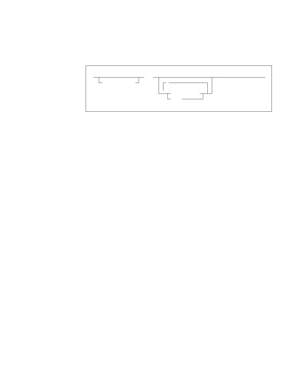
v Frees base registers previously assigned by the USING instruction for other
programming purposes
v Ensures that the assembler uses the base register you want in a particular coding
situation, for example, when two USING ranges overlap or coincide
►►
DROP
►◄
sequence_symbol
,
▼
base_register
label
sequence_symbol
Is a sequence symbol.
base_register
Is an absolute expression whose value represents one of the general registers 0
through 15. The expression in base_register indicates a general register,
previously specified in the operand of an ordinary USING statement, that is no
longer to be used for base addressing.
label
Is one of the following:
v An ordinary symbol
v A variable symbol that has been assigned a character string with a value that
is valid for an ordinary symbol
The ordinary symbol denoted by label must be a symbol previously used in the
name field of a labeled USING statement or a labeled dependent USING
statement.
If base_register or label are not specified in the operand of a DROP instruction, all
active base registers assigned by ordinary, labeled, and labeled dependent USING
instructions are dropped.
After a DROP instruction:
v The assembler does not use the register or registers specified in the DROP
instruction as base registers. A register made unavailable as a base register by a
DROP instruction can be reassigned as a base register by a subsequent USING
instruction.
v The label or labels specified in the DROP instruction are no longer available as
symbol qualifiers. A label made unavailable as a symbol qualifier by a DROP
instruction can be reassigned as a symbol qualifier by a subsequent labeled
USING instruction.
The following statements, for example, stop the assembler using registers 7 and 11
as base registers, and the label FIRST as a symbol qualifier:
DROP
7,11
DROP
FIRST
Labeled USING
You cannot end the domain of a labeled USING instruction by coding a DROP
instruction that specifies the same registers as were specified in the labeled USING
Chapter 5. Assembler instruction statements
177
instruction. If you want to end the domain of a labeled USING instruction, you
must code a DROP instruction with an operand that specifies the label of the
labeled USING instruction.
Dependent USING
To end the domain of a dependent USING instruction, you must end the domain
of the corresponding ordinary USING instruction. In the following example, the
DROP instruction prevents the assembler from using register 12 as a base register.
The DROP instruction causes the assembler to end the domain of the ordinary
USING instruction and the domains of the two dependent USING instructions. The
storage areas represented by INREC and OUTREC are both within the range of the
ordinary USING instruction (register 12).
USING
*,12
USING
RECMAP,INREC
USING
RECMAP,OUTREC
DROP
12
INREC
DS
CL156
OUTREC
DS
CL156
To end the domain of a labeled dependent USING instruction, you can code a
DROP instruction with the USING label in the operand. The following example
shows this:
USING
*,12
PRIOR
USING
RECMAP,INREC
POST
USING
RECMAP,OUTREC
DROP
PRIOR,POST
INREC
DS
CL156
OUTREC
DS
CL156
In the above example, the DROP instruction makes the labels PRIOR and POST
unavailable as symbol qualifiers.
When a labeled dependent USING domain is dropped, none of any subordinate
USING domains are dropped. In the following example the labeled dependent
USING BLBL1 is not dropped, even though it is dependent on the USING ALBL2
that is dropped:
USING
DSECTA,14
ALBL1
USING
DSECTA,14
USING
DSECTB,ALBL1.A
ALBL2
USING
DSECTA,ALBL1.A
BLBL1
USING
DSECTA,ALBL2.A+4
DROP
ALBL2
DSECTA DSECT
A
DS
A
DSECTB
DSECT
B
DS
A
178
HLASM V1R6 Language Reference

A DROP instruction is not needed:
v If the base address is being changed by a new ordinary USING instruction, and
the same base register is assigned. However, the new base address must be
loaded into the base register by an appropriate sequence of instructions.
v If the base address is being changed by a new labeled USING instruction or a
new labeled dependent USING instruction, and the same USING label is
assigned. The correct base address must be loaded into the base register
specified in the USING instruction by an appropriate sequence of instructions.
v At the end of a source module
DS instruction
The DS instruction:
v Reserves areas of storage
v Provides labels for these areas
v Uses these areas by referring to the symbols defined as labels
v If a control section has not previously been established, DS initiates an unnamed
(private) control section
,
▼
►►
DS
operand
►◄
symbol
symbol
Is one of the following:
v An ordinary symbol
v A variable symbol that has been assigned a character string with a value that
is valid for an ordinary symbol
v A sequence symbol
If symbol denotes an ordinary symbol, the ordinary symbol represents the
address of the first byte of the storage area reserved. If several operands are
specified, the first storage area defined is addressable by the ordinary symbol.
The other storage areas can be reached by relative addressing.
operand
Is an operand of six subfields. The first five subfields describe the attributes of
the symbol. The sixth subfield provides the nominal values that determine the
implicit lengths; however no constants are generated.
A DS operand has this format:
►►
type
►
duplication_factor
type_extension
program_type
►
nominal_value
►◄
modifier
Chapter 5. Assembler instruction statements
179
The format of the DS operand is identical to that of the DC operand; exactly the
same subfields are used and are written in exactly the same sequence as they are
in the DC operand. For more information about the subfields of the DC
instruction, see “DC instruction” on page 129.
Unlike the DC instruction, the DS instruction causes no data to be assembled.
Therefore, you do not have to specify the nominal value (sixth subfield) of a DS
instruction operand. The DS instruction is the best way of symbolically defining
storage for work areas, input and output buffers, and so on.
Although the formats are identical, there are two differences in the specification of
subfields. They are:
v The nominal value subfield is optional in a DS operand, but it is mandatory in a
DC operand. If a nominal value is specified in a DS operand, it must be valid.
v The maximum length that can be specified for the character (C) and hexadecimal
(X) type areas is 65,535 bytes rather than 256 bytes for the same DC operands.
The maximum length for the graphic (G) type is 65,534 bytes.
If symbol denotes an ordinary symbol, the ordinary symbol, as with the DC
instruction:
v Has an address value of the first byte of the area reserved, after any boundary
alignment is done
v Has a length attribute value, depending on the implicit or explicit length of the
type of area reserved
If the DS instruction is specified with more than one operand or more than one
nominal value in the operand, the label addresses the area reserved for the field
that corresponds to the first nominal value of the first operand. The length
attribute value is equal to the length explicitly specified or implicit in the first
operand.
Bytes skipped for alignment
Unlike the DC instruction, bytes skipped for alignment are not set to zero. Also,
nothing is assembled into the storage area reserved by a DS instruction. No
assumption should be made as to the contents of the skipped bytes or the reserved
area.
The size of a storage area that can be reserved by a DS instruction is limited only
by the size of virtual storage or by the maximum value of the location counter,
whichever is smaller.
How to use the DS instruction
Use the DS instruction to:
v Reserve storage
v Force alignment of the location counter so that the data that follows is on a
particular storage boundary
v Name fields in a storage area.
To reserve storage
If you want to take advantage of automatic boundary alignment (if the ALIGN
option is specified) and implicit length calculation, do not supply a length modifier
in your operand specifications. Instead, specify a type subfield that corresponds to
the type of area you need for your instructions.
180
HLASM V1R6 Language Reference