Volvo S60 (2018 year). Manual - part 20


  Index      Volvo     Volvo S60 - service manual 2018 year in english


Search            


Content   ..  18  19  20  21   ..


Volvo S60 (2018 year). Manual - part 20


MAINTENANCE AND SERVICING

332

Engine compartment – coolant

Normally, the coolant does not need to be
changed. If the system must be drained, consult
a trained and qualified Volvo service technician.

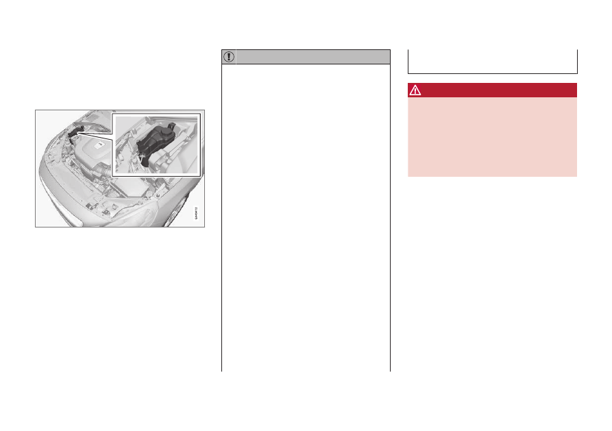
Level check and filling

Location of the coolant reservoir

See Fuel tank volume – specification and volume
(p. 377) for information on cooling system
capacities.

CAUTION

If necessary, top up the cooling system
with Volvo Genuine Coolant/Antifreeze
only (a 50/50 mix of water and anti-
freeze).

Different types of antifreeze/coolant may
not be mixed.

If the cooling system is drained, it should
be flushed with clean water or premixed
anti-freeze before it is refilled with the
correct mixture of water/anti-freeze.

The cooling system must always be kept
filled to the correct level, and the level
must be between the MIN and MAX
marks. If it is not kept filled, there can be
high local temperatures in the engine
which could result in damage. Check
coolant regularly!

Do not top up with water only. This
reduces the rust-protective and anti-
freeze qualities of the coolant and has a
lower boiling point. It can also cause
damage to the cooling system if it should
freeze.

Do not use chlorinated tap water in the
vehicle's cooling system.

If there is coolant under the vehicle, if you
detect coolant fumes or if it necessary to
top up with more than approx. 2 qts (2 lit-
ers) of coolant, engine damage could

occur if the vehicle is driven. Have it
towed to an authorized Volvo workshop.

WARNING

Never remove the expansion tank cap
while the engine is warm. Wait until the
engine cools.

If it is necessary to top off the coolant
when the engine is warm, unscrew the
expansion tank cap slowly so that the
overpressure dissipates.

MAINTENANCE AND SERVICING

}}

333

Engine compartment – brake fluid

The brake fluid should always be between the
MIN and MAX marks on the inside of the reser-
voir.

Location of the brake fluid reservoir

Checking the level

The fluid reservoir is concealed under the round
cover at the rear of the engine compartment. The
round cover must be removed first before the
reservoir cap can be accessed.

Check, without removing the cap, that there is
sufficient fluid in the reservoir.

Fluid type: DOT 4 boiling point >536 °F
(>280 °C).

Replace: The fluid should be replaced according
to the intervals specified in the Warranty and
Service Records Information booklet.

When driving under extremely hard conditions
(mountain driving, etc), it may be necessary to
replace the fluid more often. Consult a trained
and qualified Volvo service technician.

Always entrust brake fluid changing to a trained
and qualified Volvo service technician.

WARNING

If the fluid level is below the MIN mark in
the reservoir or if a brake-related mes-
sage is shown in the information display:
DO NOT DRIVE. Have the car towed to a
trained and qualified Volvo service techni-
cian and have the brake system inspec-
ted.

Dot 4 should never be mixed with any
other type of brake fluid.

Filling

1. Turn and open the cover.

2. Unscrew the reservoir cap and fill the fluid.

The level must be between the MIN and
MAX marks.

Engine compartment – power

steering fluid

The fluid level must be between the 

MIN and

MAX marks. For capacities and recommended
fluid grade, see Fuel tank volume – specification
and volume (p. 377).

Check the level frequently. It does not normally
require changing.

WARNING

If a problem should occur in the power steer-
ing system or if the vehicle has no electrical
current and must be towed, it is still possible
to steer the vehicle. However, keep in mind
that greater effort will be required to turn the
steering wheel.

MAINTENANCE AND SERVICING

334

CAUTION

Keep the area around the power steering
fluid reservoir clean when checking.

Bulbs – introduction

Certain bulbs can be replaced by the vehicle's
owner. However, the bulbs on the following list
should only be replaced by a trained and quali-
fied Volvo service technician.

All bulb specifications are listed in Bulbs – speci-
fications (p. 341).

Active Bending Lights

Front parking lights

Front side marker lights

Cornering lights

Turn signals in the door mirrors

Approach lighting in the door mirrors

Interior lighting (except for the front footwell
lighting)

Rear parking lights

LED bulbs

NOTE

For information regarding any bulbs not
mentioned in this section, please contact
your Volvo retailer or a trained and
authorized Volvo service technician.

Always switch off the ignition before star-
ting to replace a bulb.

If an error message remains in the dis-
play after a faulty bulb has been replaced,
contact an authorized Volvo workshop.

Condensation may form temporarily on
the inside of the lenses of exterior lights
such as headlights, fog lights, or taillights.
This is normal and the lights are
designed to withstand moisture. Normally,
condensation will dissipate after the
lights have been on for a short time.

The optional Active Bending Light bulbs
contain trace amounts of mercury. These
bulbs should always be disposed of by a
trained and qualified Volvo service techni-
cian.

CAUTION

Never touch the glass of bulbs with your fin-
gers. Grease and oils from your fingers vapor-
ize in the heat and will leave a deposit on the
reflector, which will damage it.

MAINTENANCE AND SERVICING

}}

* Option/accessory.

335

WARNING

The engine should not be running when
changing bulbs.

If the engine has been running just prior
to replacing bulbs in the headlight hous-
ing, please keep in mind that components
in the engine compartment will be hot.

WARNING

Active Bending Lights

* – due to the high

voltage used by these headlights, these
bulbs should only be replaced by a
trained and qualified Volvo service techni-
cian.

Turn off the lights and remove the remote
key from the ignition before changing any
bulbs.

Related information

Bulbs – headlight housing (p. 335)

Bulbs – taillight housing (p. 340)

Bulbs – vanity mirror lighting (p. 341)

Bulbs – license plate lighting (p. 340)

Bulbs – headlight housing

The entire headlight housing must be lifted out
when replacing all front bulbs.

Removing the headlight housing

Pull out the headlight housing's locking pins.

Remove the headlight housing by alterna-
tively pulling the front and rear edges until it
can be lifted out.

CAUTION

When disconnecting the connector, pull on
the connector itself and not on the wiring.

Unplug the wiring connector by holding down
the clip with your thumb.
Pull the connector out with the other hand.

5. Lift out the headlight housing and place it on

a soft surface to avoid scratching the lens.

6. Replace the defective bulb(s).

Reinserting the headlight housing

1. Plug in the connector until it clicks into place.

||

MAINTENANCE AND SERVICING

336

2. Reinstall the headlight housing and locking

pins. The short locking pin should be closest
to the grille. Check that they are correctly
inserted.

The headlight housing must be properly in
place and the wiring connector correctly
reconnected before the lighting is switched
on or the remote key is inserted into the igni-
tion slot.

3. Check that the lights function properly.

Related information

Bulbs – introduction (p. 334)

Bulbs – cover (p. 336)

Bulbs – specifications (p. 341)

Bulbs – cover

The larger cover has to be removed in order to
change the high/low beam headlight bulbs.

Removing the cover to access the
bulbs

NOTE

Before starting to replace a bulb, see Bulbs –
introduction (p. 334).

1. Loosen the cover's four retaining screws

(3-4 turns) with a Torx T20 tool (1). The
screws should not be removed completely.

2. Push the cover to the side.

3. Remove the cover.

Reinstall the cover in the reverse order.

Related information

Bulbs – headlight housing (p. 335)

Bulbs – low beam, Halogen (p. 337)

Bulbs – high beam, Halogen (p. 337)

Bulbs – extra high beam (p. 338)

MAINTENANCE AND SERVICING

337

Bulbs – low beam, Halogen

The low beam bulb is concealed by the larger
cover.

1. Remove the headlight housing from the vehi-

cle (see Bulbs – headlight housing (p. 335)).

2. Remove the cover over the bulbs (see Bulbs

– cover (p. 336)).

3. Unplug the connector from the bulb.

4. Remove the bulb by pulling it straight out.

5. The guide lug on the new bulb should be

straight up when the bulb is inserted into the
holder and the bulb should snap into place.

6. Put the cover back into position and reinstall

the headlight housing.

Related information

Bulbs – specifications (p. 341)

Bulbs – high beam, Halogen

The high beam bulb is concealed behind the
larger cover.

1. Remove the headlight housing from the vehi-

cle (see Bulbs – headlight housing (p. 335)).

2. Remove the cover over the bulbs (see Bulbs

– cover (p. 336)).

3. Remove the bulb by turning it counterclock-

wise and pulling it straight out.

4. Remove the connector from the bulb.

5. Press the new bulb into the socket and turn

it clockwise to put it in place. It can only be
secured in one position.

6. Reinsert the bulb holder into the headlight

housing.

7. Put the cover back into position and reinstall

the headlight housing.

Related information

Bulbs – specifications (p. 341)

MAINTENANCE AND SERVICING

338

Bulbs – extra high beam

The extra high beam bulb is concealed by the
larger cover.

Extra high beam

2

1. Remove the headlight housing from the vehi-

cle (see Bulbs – headlight housing (p. 335)).

2. Remove the cover over the bulbs (see Bulbs

– cover (p. 336)).

3. Remove the bulb by turning it counterclock-

wise and pulling it straight out.

4. Remove the connector from the bulb.

5. Press the new bulb into the socket and turn

it clockwise to put it in place. It can only be
secured in one position.

6. Put the cover back into position and reinstall

the headlight housing.

Related information

Bulbs – specifications (p. 341)

Bulbs – front turn signals

The turn signal bulb is concealed behind the
smaller cover.

1. Remove the headlight housing from the vehi-

cle (see Bulbs – headlight housing (p. 335)).

2. Remove the cover by pulling it straight out.

3. Pull the holder to access the bulb.

4. Press in the bulb and turn it to remove it

from the holder.

5. Press and turn the new bulb into place.

6. Reinsert the bulb holder into the headlight

housing.

7. Put the cover back into position and reinstall

the headlight housing.

2

Models with optional Active Bending Lights only.

MAINTENANCE AND SERVICING

339

Related information

Bulbs – specifications (p. 341)

Bulbs – location of taillight bulbs

The following illustrations show the location of
the bulbs in the taillight cluster.

Taillight lens, right side

Brake light (LEDs)

Side marker light (LEDs)

Brake light

Parking light (LEDs)

Backup light

Turn signal

Rear fog light

Backup lights

1. Open the panel in the trunk.

2. Remove the bulb holder by turning it coun-

terclockwise.

3. Remove the defective bulb by pressing it in

slightly and turning it counterclockwise
before pulling it out.

4. Insert a new bulb, press it in and turn it

clockwise.

5. Reinsert the bulb holder by turning it clock-

wise.

Related information

Bulbs – introduction (p. 334)

Bulbs – specifications (p. 341)

MAINTENANCE AND SERVICING

340

Bulbs – taillight housing

The bulbs in the taillight cluster are replaced
from inside the trunk (not the LED functions).

NOTE

Before starting to replace a bulb, see Bulbs –
introduction (p. 334).

1. Remove the covers in the left/right panel to

access the bulb holder.

2. Press the catches together and pull out the

bulb holder.

3. Remove the defective bulb by pressing it in

slightly and it turning counterclockwise
before pulling it out.

4. Insert a new bulb, press it in slightly and turn

it clockwise.

5. Press the bulb holder back into place and

reinstall the cover.

Related information

Bulbs – introduction (p. 334)

Bulbs – location of taillight bulbs (p. 339)

Bulbs – specifications (p. 341)

Bulbs – license plate lighting

The license plate lighting is located next to the
trunk handle.

1. Remove the screws with a screwdriver.

2. Carefully detach the entire bulb housing and

pull it out.

3. Replace the bulb.

4. Reinsert the entire bulb housing and tighten

the screws.

Related information

Bulbs – specifications (p. 341)

MAINTENANCE AND SERVICING

}}

* Option/accessory.

341

Bulbs – trunk lighting

The trunk lighting is located on opposite sides of
the trunk.

G021758

1. Insert a screwdriver and gently turn so that

the bulb housing comes loose.

2. Replace the bulb.

3. Check that the bulb illuminates and press it

back into the bulb housing.

Related information

Bulbs – specifications (p. 341)

Bulbs – vanity mirror lighting

The vanity mirror bulbs are located behind the
lens.

Removing the lens

1. Insert a screwdriver underneath the side of

the lens and carefully pry up the lug on the
edge.

2. Carefully detach and lift out the lens.

3. Use needle nose pliers to pull the bulb

straight to the side. Replace the bulb. Do not
exert too much pressure on the bulb with the
pliers to help avoid damaging it.

Reinstalling the lens

1. Put the lens back into position.

2. Press it into place.

Related information

Bulbs – specifications (p. 341)

Bulbs – specifications

The following bulbs can be replaced by the vehi-
cles owner. All other bulbs should only be
replaced by a trained and qualified Volvo service
technician.

Lighting function

Wat-

tage

Bulb

Extra high beam
(models with
Active Bending
Lights

*)

55

H7 LL

Low beam (halo-
gen)

55

H11 LL

High beam (halo-
gen)

65

H9

Front turn signals

24

PY24W

License plate light-
ing

5

C5W LL

Vanity mirror light-
ing

1.2

W2x4.6d type

T5

Glove compart-
ment lighting

5

SV8.5 (length

43mm)

Rear turn signals

21

PY21W LL

Rear fog light

21

H21W LL

||

MAINTENANCE AND SERVICING

342

Lighting function

Wat-

tage

Bulb

Backup light

21

H21W LL

Brake light

21

P21W LL

Trunk lighting

10

SV8.5 (length

38mm)

Front footwell
lighting

3

W2, 1x9.5d

type T10

NOTE

Please consult a Volvo retailer’s Parts depart-
ment for the most up-to-date bulb specifica-
tions.

Related information

Bulbs – introduction (p. 334)

Wiper blades – service position

The windshield wiper blades must be in the verti-
cal (service) position for replacement, washing
or to lift them away from the windshield when
e.g., removing ice or snow.

Wiper blades in service position

CAUTION

Be sure the wiper blades are not frozen in
position before attempting to move them to
the service position.

To put the windshiield wipers in the service posi-
tion:

1. Insert the remote key into the ignition slot

3

and press the START/STOP ENGINE but-
ton briefly to put the ignition in mode I (see
Ignition modes (p. 74) for detailed informa-
tion about the ignition modes).

2. Press the START/STOP ENGINE button

again briefly to switch the ignition off.

3. Within 3 seconds, move the right steering

wheel lever up and hold it for at least 1 sec-
ond.
> The wipers will then move to the vertical

(service) position on the windshield.

The wipers can be returned to the normal posi-
tion by pressing the START/STOP ENGINE but-
ton briefly to put the ignition in mode I (or by
starting the engine).

CAUTION

If the wiper arms have been folded out from
the windshield while in the service position,
fold them back against the windshield before
returning the wipers to the normal position to
help avoid scratching the paint on the hood.

Related information

Engine compartment – washer fluid (p. 344)

3

Not necessary on vehicles with the optional keyless drive.

MAINTENANCE AND SERVICING

343

Wiper blades – windshield

The wiper blades should be replaced regularly
for best effect.

The windshield wiper blades must be in the verti-
cal (service) position for replacement, washing
or to lift them away from the windshield when
e.g., removing ice or snow.

Replacing the windshield wiper blades

NOTE

The windshield wiper blades are different
lengths. The blade on the driver’s side is
longer than the one on the passenger side.

With the wipers in the service position, fold
out the wiper arm from the windshield. Press
the button on the wiper blade attachment
and pull the wiper blade straight out, parallel
with the wiper arm.

Slide in the new wiper blade until it clicks
into place.

Check that the blade is securely in place.

4. Press the wipers back against the wind-

shield.

To return the wipers from the service position to
the normal position, fold the wipers back against
the windshield and press the START/STOP
ENGINE button briefly to put the ignition in mode
I (or start the engine).

Cleaning

Keeping the windshield and wiper blades clean
helps improve visibility and prolongs the service
life of the wiper blades. Clean the wiper blades
with a stiff-bristle brush and lukewarm soap solu-
tion or car washing detergent.

Related information

Engine compartment – washer fluid (p. 344)

Wiper blades – service position (p. 342)

MAINTENANCE AND SERVICING

344

Engine compartment – washer fluid

Washer fluid helps keep the windshield and
headlights clean. During cold weather, the reser-
voir should be filled with windshield washer sol-
vent containing antifreeze. Use Volvo Original
Washer Fluid or the equivalent with a recom-
mended pH value between 6 and 8.

Location of the washer fluid reservoir

The windshield and headlight washers share a
common reservoir.

The washer fluid reservoir is located on the driv-
er's side of the engine compartment. For capaci-
ties, see the printed Owner's Manual.

Specification:Use a washer antifreeze recom-
mended by Volvo, mixed with water.

Volume:

6.8 US qts (6.5 liters)

4.7 US qts (4.5 liters

4

)

Related information

Wiper blades – service position (p. 342)

Battery – symbols

There are information and warning symbols on
the battery.

Symbols on the battery

Wear protective goggles.

Keep away from children.

Avoid smoking, open
flames, and/or sparks.

See the owner's manual.

4

Models without headlight washers

MAINTENANCE AND SERVICING

}}

345

Contains corrosive acid.

Risk of explosion

Recycle properly

NOTE

Used batteries should be disposed of in an
environmentally responsible manner. Consult
your Volvo retailer or take the used batteries
to a recycling station.

Related information

Battery – changing (p. 347)

Battery – handling (p. 345)

Battery – maintenance (p. 346)

Battery – handling

The battery's service life is affected by the num-
ber of starts, if it has been discharged, driving
style, driving conditions, weather conditions ,etc.

Handling

Check that the battery cables are correctly
connected and tightened.

Never disconnect the battery when the
engine is running (for example, when replac-
ing the battery).

If the battery is fully discharged a number of
times, this may shorten its service life.

The service life of a battery is affected by
factors such as the number of starts, driving
conditions and climate. Extreme cold may
also further decrease the battery’s starting
capacity.

Because the battery’s starting capacity
decreases with time, it may be necessary to
recharge it if the vehicle is not driven for an
extended period of time or if the vehicle is
usually only driven short distances.

Never use a quick charger to charge the bat-
tery. Only traditional types of battery chargers
should be used.

CAUTION

The infotainment system's energy-saving fea-
ture may not function correctly or at all,
and/or a message may be displayed if a bat-
tery charger or jumper cables are not con-
nected properly.

The negative terminal on the battery must
never be used to connect a jumper cable
or a battery charger. Only the ground
point on the chassis may be used.

See Jump starting (p. 254) for an illustration
and additional information.

WARNING

Never expose the battery to open flame
or electric spark.

Do not smoke near the battery.

Battery fluid contains sulfuric acid. Do not
allow battery fluid to contact eyes, skin,
fabrics or painted surfaces. If contact
occurs, flush the affected area immedi-
ately with water. Obtain medical help
immediately if eyes are affected.

NOTE

The life of the battery is shortened if it
becomes discharged repeatedly.

||

MAINTENANCE AND SERVICING

346

Related information

Battery – changing (p. 347)

Battery – maintenance (p. 346)

Battery – symbols (p. 344)

Battery – maintenance

Proper battery maintenance can help prolong its
service life.

Maintenance

Use a screw driver to open the caps or cover
and a flashlight to inspect the level.

If necessary, add distilled water. The level
should never be above the indicator.

The fluid level should be checked if the bat-
tery has been recharged.

After inspection, be sure the cap over each
battery cell or the cover is securely in place.

Check that the battery cables are correctly
connected and properly tightened.

Never disconnect the battery when the
engine is running, or when the key is in the
ignition. This could damage the vehicle's
electrical system.

The battery should be disconnected from the
vehicle when a battery charger is used
directly on the battery.

To help keep the battery in good condition,
the vehicle should be driven for at least 15
minutes a week or connected to a charger
with an automatic charging function.

If the battery is fully discharged a number of
times, this may shorten its service life. Keep-
ing the battery fully charged helps prolong its
service life.

The service life of a battery is affected by
factors such as driving conditions and cli-
mate. Extreme cold may also further
decrease the battery’s starting capacity.

Because the battery’s starting capacity
decreases with time, it may be necessary to
recharge it if the vehicle is not driven for an
extended period of time or if the vehicle is
usually only driven short distances.

CAUTION

Always use distilled or deionized water
(battery water).

Never fill above the level mark in the cell.

Related information

Battery – changing (p. 347)

Battery – handling (p. 345)

Battery – symbols (p. 344)

MAINTENANCE AND SERVICING

}}

347

Battery – changing

When changing batteries, be sure to use the
correct battery for your vehicle. Consult a Volvo
retailer or a trained and qualified Volvo service
technician.

Changing

WARNING

Connect and disconnect the positive and neg-
ative cables in the correct sequence.


Content   ..  18  19  20  21   ..