Volkswagen New Beetle. Manual - part 669


  Index      Volkswagen     Volkswagen New Beetle 1998-2008 year - service repair manual


Search            


Content   ..  667  668  669  670   ..


Volkswagen New Beetle. Manual - part 669


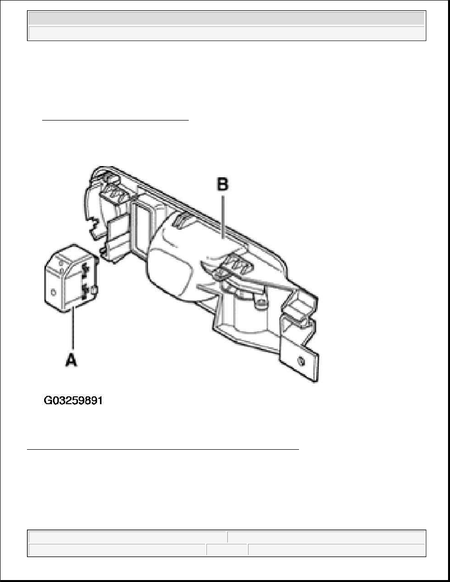
The hydraulic unit -a- and control module -b- (47 pin) form one component. Separating is only possible when 
removed. 

New control modules service via the replacement parts are not coded and require coding after installation. 

See ABS CONTROL MODULE, CODING . 

Fig. 36: Identifying Hydraulic Unit And Control Module - Mark 60 ABS 
Courtesy of VOLKSWAGEN OF AMERICA, INC. 

DISTINGUISHING FEATURES OF ABS MARK 60 

ABS/EDL/ASR/ESP Mark 60 


2003 Volkswagen New Beetle GLS 

1998-2004 BRAKES Anti-Lock Brake System - New Beetle


Fig. 37: Identifying ABS/EDL/ASR/ESP Mark 60 Dimensions 
Courtesy of VOLKSWAGEN OF AMERICA, INC. 

Dimension a = 100 mm 

1. Control module, 47-pin (screwed to hydraulic unit). Two 4.8 mm wide contacts are located at both ends 

of the connection.  

NOTES FOR REPAIR WORK ON ABS, ABS/EDL 

z

Before working on the anti-locking system, determine the cause of the malfunction On Board Diagnostic 
(OBD). 

See ON BOARD DIAGNOSTIC (OBD), PERFORMING 

z

Before working on the ABS, ABS/EDL system, disconnect the battery Ground strap. Obtain coding, on 


2003 Volkswagen New Beetle GLS 

1998-2004 BRAKES Anti-Lock Brake System - New Beetle


vehicles with coded radio.  

z

Before carrying out welding work with an electric welding unit, disconnect the ABS control module.  

z

When working with brake fluid, observe the relevant safety precautions and notes.  

z

Work for which the brake system has to be opened, bleed the brake system with brake filler and bleeder 
unit VAS 5234.  

z

During the final road test, make sure that a controlled brake test is performed at least once (pulsations 
must be felt at the brake pedal).  

z

Absolute cleanliness is required when working on the anti-locking brake system, it is not permitted to use 
any products which contain mineral oil, such as oils, greases etc.  

z

Thoroughly clean all unions and the adjacent areas before loosening, do not use aggressive cleaning 
agents such as brake cleaner, gas, thinners or similar.  

z

Place removed parts on a clean surface and cover.  

z

After separating the control module/hydraulic unit use the transportation protection for the valve dome.  

z

Carefully cover or seal open components if repairs cannot be carried out immediately. (Use sealing plugs 
repair kit 1 H0 693 311 A).  

z

Do not use fluffy cloths.  

z

Only remove replacement parts from packaging immediately prior to installation.  

z

Only use genuine packed parts.  

z

When the system is open do not work with compressed air and do not move the vehicle.  

z

Make sure no brake fluid enters plug connectors.  

HYDRAULIC UNIT, BRAKE BOOSTER/BRAKE MASTER CYLINDER - 
ASSEMBLY OVERVIEW MARK 60 

1. Brake booster, left-hand drive 

z

On gasoline engines the vacuum required is taken from the intake manifold.  

z

On Diesel engines a vacuum pump is installed to create the required vacuum.  

z

On some vehicles an electrical brake system vacuum pump -V192- is installed  

z

Functional check 

„

With engine not running, depress brake pedal firmly several times (to exhaust the vacuum in 
the module).  

„

Now depress brake pedal with average foot pressure, hold and start engine. If the booster 
module is working properly, the pedal will be felt to give slightly under foot (booster 
assistance becomes effective).  

z

If faulty, replace complete  

NOTE:

Complete master cylinder and brake booster can be replaced independently of 
each other.

NOTE:

The following list refers to items in Fig. 38 .


2003 Volkswagen New Beetle GLS 

1998-2004 BRAKES Anti-Lock Brake System - New Beetle


z

Non-return valve (in vacuum hose). 

Functional check. See VACUUM CHECK VALVE . 

z

Separating from brake pedal. See BRAKE BOOSTER .  

z

Removing and installing. See BRAKE BOOSTER .  

2. Sealing cap  

3. Brake fluid reservoir, left-hand drive (LHD)  

4. Sealing plugs 

z

Moisten with brake fluid and install into brake fluid reservoir  

5. Retaining pin 

z

Insert through brake master cylinder  

6. Brake master cylinder, left-hand drive (LHD) 

z

Must not be repaired. If faulty, replace complete.  

7. Brake line 

z

Brake master cylinder (primary circuit) to hydraulic unit  

8. Connection for brake line 

z

Hydraulic unit to left front brake caliper  

9. Connection for brake line 

z

Hydraulic unit to right front brake caliper  

10. Brake line 

z

Brake master cylinder (secondary circuit) to hydraulic unit  

11. Control module 

z

Do not disconnect connector before performing On Board Diagnosis (OBD)  

12. Hydraulic unit ABS/EDL  

13. Bracket  

14. Hex nut, 20 N.m (15 ft. lb)  

15. Bolts, 8 N.m (70 in lb)  

16. Torx socket head bolt E5, 4 N.m (35 in lb)  

17. Connection for brake line 

z

Hydraulic unit to left rear wheel cylinder/brake caliper  

18. Connection for brake line 

z

Hydraulic unit to right rear wheel cylinder/brake caliper  

19. Brake fluid reservoir, right-hand drive (RHD)  

20. Sealing plugs 

z

Moisten with brake fluid and install into brake fluid reservoir  

21. Bleed valve  

22. Retaining plate 


2003 Volkswagen New Beetle GLS 

1998-2004 BRAKES Anti-Lock Brake System - New Beetle


Content   ..  667  668  669  670   ..