Volkswagen Golf Variant / Jetta. Manual - part 438


  Index      Volkswagen     Volkswagen Golf Variant (2007), Jetta (2005) - service repair manual


Search            


Content   ..  436  437  438  439   ..


Volkswagen Golf Variant / Jetta. Manual - part 438


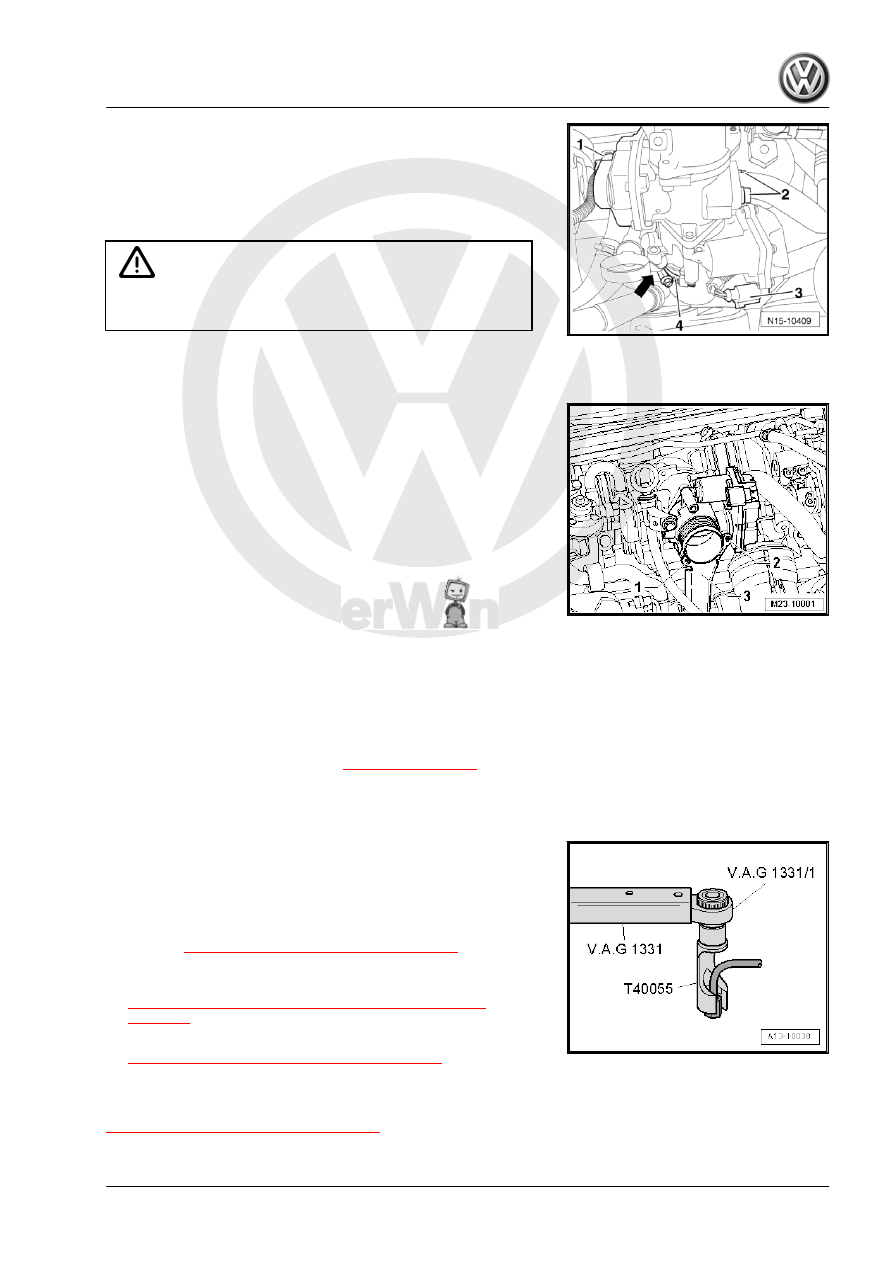
Throttle Valve Control Module - J338- -3-.

– Loosen the clamp -4- and remove the charge air hose.
– Remove the oil dipstick bracket -arrow-.
– Disconnect the connecting pipe -2-.

Caution

Make sure the connecting pipe decoupling element does not

bend or stretch. Cracks could develop.

– Remove the bolts -1 and 2- from the Throttle Valve Control

Module - J338- and remove the bracket.

– Remove the intake manifold bolts with a Socket - Xzn 8 -

T40159- in a diagonal sequence working from the outside

toward the inside.

– Remove intake manifold.
Installing:
Install in reverse order of removal. Note the following:
• Always replace the seals.
• When installing the high pressure line or fuel lines, make sure

no dirt enters the fuel system.

• Only remove the plugs right before installing the fuel lines.
• Do not change the angles of the high pressure lines
• Make sure the line connections are secure.
• Do not interchange the supply line and the return line.
– Tighten the intake manifold bolts in a diagonal sequence start‐

ing from the inside toward the outside:

• Tightening specification -item 2- 

⇒ Item 2 (page 332)

 .

– Tighten the high pressure line union nuts hand-tight.
– Make sure the high pressure line is without tension.

– Tighten the high pressure line using the Torque Wrench 1331

5-50Nm - VAG1331- with Torque Wrench 1331 Insert - Re‐

versible Ratchet - VAG1331/1- and Union Nut Socket -

T40055- .

Tightening Specifications:
• Refer to 

⇒ “3.3 Overview - Fuel System”, page 311

 . Overview

- Fuel System

• Overview - Intake Manifold with Attachments. Refer to

⇒ “3.12 Overview - Intake Manifold with Attachments”,

page 331

 .

– Fill the fuel system. Refer to

⇒ “3.9 Fuel System, Filling/Bleeding”, page 328

 .

3.14

Overview - Air Filter

⇒ “3.14.1 Overview - Air Filter”, page 335

3.14.1

Overview - Air Filter

3. Diesel Direct Injection System    

335

❑ Check for secure fit
❑ Clean if there is contam‐

ination

❑ To the intake scoop on

the turbocharger

-item 35-

⇒ Item 35 (page 273)

2 - Mass Airflow Sensor - G70-

❑ Removing and instal‐

ling. Refer to

⇒ “3.17  Mass Airflow

Sensor G70 , Removing

and Installing”,

page 341

 .

3 - O-Ring

❑ Replace if damaged

4 - Vacuum Hose

❑ Check for secure fit and

kink free routing

❑ From the muffler
❑ Connection diagram for

vacuum hoses. Refer to

⇒ “4.5 Vacuum Hose

Connection Diagram”,

page 295

 .

5 - Screw

❑ 2 Nm

6 - Air Filter Housing Upper

Section

❑ Clean salt residue, dirt

and leaves from the air

filter housing-upper sec‐

tion

7 - Intake Air Duct

❑ Bolted to the lock carrier

8 - Screw

❑ 5 Nm

9 - Air Duct Hose

❑ Check for secure fit
❑ Clean if there is contamination

10 - Water Drain Hose

❑ Clean if there is contamination

11 - Lower Section of Air Filter Housing

❑ Clean salt residue, dirt and leaves from the lower section of the air filter housing.

12 - Connecting Hose

❑ For the warm air intake
❑ Check for secure fit
❑ Clean if there is contamination
❑ From the warm air collector plate on the exhaust manifold -item 2- 

⇒ Item 2 (page 271)

 .

13 - Bolt

❑ 8 Nm

336

14 - Snow Screen

❑ Clean if there is contamination

15 - Filter Element

❑ Always use Original air filter insert Parts Catalog.
❑ Follow the replacement intervals ⇒  Maintenance Intervals; Rep. Gr.  03 “Maintenance Tables”.
❑ Removing and installing. Refer to 

⇒ “3.16 Air Filter Element, Removing and Installing”, page 339

 .

16 - Screw

❑ 3.5 Nm

3.14.2

Overview - Air Filter, Engine Codes CBDA, CBDB, CEGA

1 - Intake Hose

❑ To the turbocharger

2 - Mass Airflow Sensor - G70-
3 - O-Ring

❑ Replace if damaged

4 - Vacuum Hose

❑ Check for secure fit and

kink free routing

❑ To the Wastegate By‐

pass Regulator Valve -

N75-

❑ Connection diagram for

vacuum hoses. Refer to

⇒ “4.6 Vacuum Hose

Connection Diagram,

Engine Codes CBDA,

CBDB, CEGA”,

page 296

 .

5 - 2 Nm
6 - Air Filter Housing Upper

Section

❑ Clean salt residue, dirt

and leaves from the air

filter housing lower sec‐

tion

7 - Air intake connector

❑ Attached to the lock car‐

rier

8 - 2 Nm
9 - Connecting Hose

❑ Check for secure fit
❑ Clean if there is contam‐

ination

10 - Water drain pipe

❑ Clean if there is contamination

11 - Lower section of air filter housing

❑ Clean salt residue, dirt and leaves from the air filter housing lower section

3. Diesel Direct Injection System    

337

❑ Always use Original air filter insert Parts Catalog.
❑ Follow the replacement intervals ⇒ Maintenance ; Booklet  20.1 ; Service Work “Maintenance Tables”.
❑ Removing and installing. Refer to 

⇒ “3.16 Air Filter Element, Removing and Installing”, page 339

 .

14 - 3.5 Nm
15 - Connecting Pipe

❑ From the cylinder head cover
❑ For the crankcase ventilation

3.15

Air Filter Housing, Removing and Instal‐

ling

Removing
– Release the tabs -arrows- and open the cover on the air intake.
– Remove the connecting hose for the warm air intake

-item 12- 

⇒ Item 12 (page 336)

 .

– Remove the screws -arrows- on the air intake -1- and pull the

connecting hose -2- off the guide.

– Press the tab -1 and 3- and remove the connecting hose -4-

from the air filter housing -2-.

– Disconnect the connector from the Mass Airflow Sensor - G70-

-1- and the vacuum line -2-.

338


Content   ..  436  437  438  439   ..