Volkswagen Golf Variant / Jetta. Manual - part 436
take manifold.
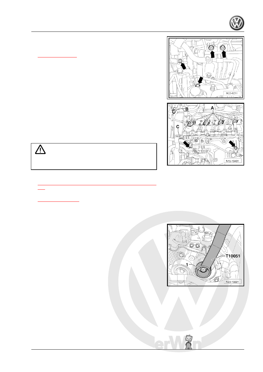
– Remove the protective strip, if equipped -item 1-
– Disconnect from the fuel injectors -A-, the Exhaust Pressure
Sensor 2 - G451- -B- and the Fuel Pressure Sensor - G247-
-C-.
– Remove the coolant line bolts -arrows- from the intake mani‐
fold and lay the line in front of the intake manifold.
– Unclip the wiring harness from the wiring guide for the glow
plugs.
Caution
Always follow the procedure »Glow Plug Connectors, Remov‐
ing and Installing«.
– Remove the glow plug connectors. Refer to
⇒ “1.3 Glow Plug Connectors, Removing and Installing”, page
– Remove the high pressure line -item 21-
between the high pressure fuel pump
and rail element (high pressure reservoir).
– Remove the toothed belt sprocket from the high pressure fuel
pump.
– Hold the high pressure fuel pump hub with the Counterhold -
Camshaft Gear - T10051- and remove the nut -1-.
3. Diesel Direct Injection System
327