Volkswagen Golf Variant / Jetta. Manual - part 419


  Index      Volkswagen     Volkswagen Golf Variant (2007), Jetta (2005) - service repair manual


Search            


Content   ..  417  418  419  420   ..


Volkswagen Golf Variant / Jetta. Manual - part 419


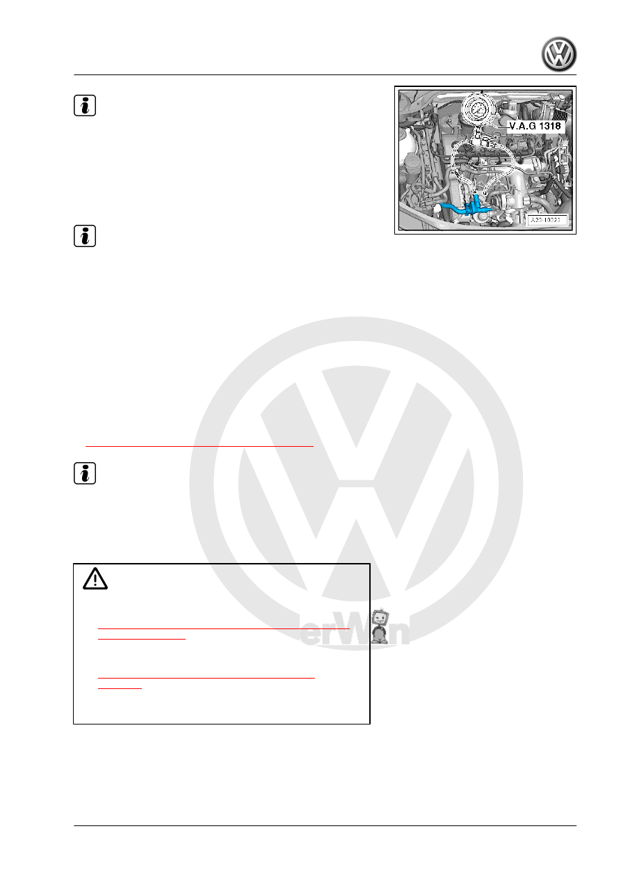
The Diesel Pressure Tester Kit - VAS6551- is switched on in

the fuel supply line.

Illustration shows VAG1318, use Diesel Pressure Tester Kit -

VAS6551- .

– Connect the Vehicle Diagnostic Tester and perform the Gui‐

ded Function “Check electrical fuel pumps”.

Note

The fuel pump is now activated for 30 seconds.

– Let the fuel pumps run until the highest fuel pressure is

reached.

• Specified value: minimum 3.5 bar (50.76 psi)
If the specified value is not obtained:
Check the connection between the fuel pressure gauge and fuel

line for leaks.
Check the pressure gauge for leaks.
Check the fuel lines and their connections for leaks.
Fuel filter clogged?
Check the delivery rate of the Transfer Fuel Pump - G6- . Refer

to 

⇒ “6.4.1 Fuel Delivery Rate, Checking”, page 252

 .

Note

Check the fuel system for leaks.

6.6

Auxiliary Fuel Pump - V393- (Inline Fuel

Pump), Removing and Installing

DANGER!

♦ Observe safety precautions when working on fuel supply.

Refer to

⇒ “1 Safety Precautions when Working on Fuel Supply

System”, page 223

 .

♦ Pay attention to the guidelines for clean working condi‐

tions. Refer to

⇒ “2 Guidelines for Clean Working Conditions”,

page 224

 .

Always pay attention to these instructions before and during

work.

Special tools and workshop equipment required
♦ Torque Wrench 1331 5-50Nm - VAG1331-
♦ Hose Clip Pliers - VAS6362-

6. Fuel Supply System, Servicing    

259

sor 2 - G451- -1-.

– Remove the bolt -4- and the bracket -3- with the Exhaust Pres‐

sure Sensor 2 - G451- -1- in the direction of -arrow- and set to

the side (control lines remain connected).

– Disconnect -1- from the Auxiliary Fuel Pump - V393- .

– Unclip the fuel hoses -2 and 3- from the holder.
– Loosen the spring clamp with the Hose Clip Pliers - VAS6362-

and remove the fuel supply line -item 6- 

⇒ Item 6 (page 250)

from the fuel filter.

– Disconnect the connector from the Fuel Temperature Sensor

- G81- -arrow-.

– Loosen the spring clamp -1- with the Hose Clip Pliers -

VAS6362- and disconnect the fuel supply line at the high

pressure fuel pump.

– Seal the lines so that no dirt can enter the fuel system.

260

Pump - V393- .

Installing:
Install in reverse order of removal. Note the following:
• Route the fuel hoses without kinks.
• Check the fuel hoses for secure fit.
• Do not interchange the supply and return lines (the return line

is blue or has a blue marking, the supply line is white or has a

white marking).

• Clip the fuel and coolant hoses back into the holders.
Tightening Specifications:
• Bolt for Exhaust Pressure Sensor 2 - G451- bracket: 8 Nm.
• Bolts for the Auxiliary Fuel Pump - V393- : 20 Nm.
– Fill the fuel system. Refer to

⇒ “3.9 Fuel System, Filling/Bleeding”, page 328

 .

6. Fuel Supply System, Servicing    

261

Electronic Engine Output Control

(EPC)

⇒ “7.1 EPC System Function”, page 262
⇒ “7.2 Overview - Accelerator Pedal Module”, page 262
⇒ “7.3 Accelerator Pedal Module, Removing and Installing”, page

263

7.1

EPC System Function

For EPC, the throttle valve is not operated by a cable from the

accelerator pedal. There is no mechanical connection between

the gas pedal and the throttle valve.
The position of the accelerator pedal is transmitted to the Engine

Control Module - J623- via two accelerator pedal position sensors

(adjustable resistances, accommodated in one housing), that are

connected to the accelerator pedal.
The position of the accelerator pedal (driver controlled) is a main

input for the Engine Control Module - J623- .
Throttle valve operation occurs via an electric motor (throttle valve

actuator) in the Throttle Valve Control Module - GX3- and this

occurs over the entire engine speed and engine load spectrum.
The throttle valve is operated by the throttle drive according to the

instructions of the Engine Control Module - J623- .
With the engine stopped and the ignition switched on, the Engine

Control Module - J623- activates the throttle valve actuator ac‐

cording to the specifications from the Throttle Position Sensor -

G69- . This means, if the accelerator pedal is depressed half way,

the throttle drive opens the throttle valve to the same degree. The

throttle valve is then opened approximately half way.
With engine running (under load) the Engine Control Module -

J623- can open and close the throttle valve independently of the

Throttle Position Sensor - G69- .
This means, for example, that the throttle valve could be fully

opened even though the accelerator pedal has only been de‐

pressed half way. This has the advantage of preventing torque

losses at the throttle valve.
After evaluating the torque requirements of the various compo‐

nents (such as the A/C system, automatic transmission, ABS/

ESP, etc.), the Engine Control Module - J623- calculates the op‐

timal throttle valve opening angle for the current situation.
Aside from that, it results in clearly better pollutant output and

consumption values under certain load conditions.
“E-Gas” is a system containing all components that contribute to

recognizing, controlling and monitoring the position of the throttle

valve, for example the Throttle Position Sensor - G69- , Throttle

Valve Control Module - GX3- , EPC Indicator Lamp - K132- , En‐

gine Control Module - J623- .

7.2

Overview - Accelerator Pedal Module

262


Content   ..  417  418  419  420   ..