Volkswagen Golf Variant / Jetta. Manual - part 380


  Index      Volkswagen     Volkswagen Golf Variant (2007), Jetta (2005) - service repair manual


Search            


Content   ..  378  379  380  381   ..


Volkswagen Golf Variant / Jetta. Manual - part 380


the cylinder head cover correctly.
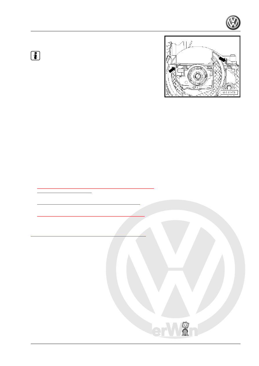
Note

The camshaft is removed here for clarity.

– Press the toothed belt guard upper section near the clips

-arrows- against the cylinder head cover until the clips engage

with each other. Use a screwdriver to press the guard if nec‐

essary.

– Check the clearance between the hub and the toothed belt

guard upper section.

– Install the right front wheel housing liner. Refer to ⇒  Body

Exterior; Rep. Gr.  66 ; Wheel Housing Liner .

50 ; Noise Insulation .

Further assembly is performed in the reverse order of the remov‐

al. Note the following:
• Route the fuel hoses without kinks.
• Check the fuel hoses for secure fit.
• Do not interchange the supply and return lines (the return line

is blue or has a blue marking, the supply line is white or has a

white marking).

• Clip the fuel hoses back into the retainers.
– Install the Auxiliary Fuel Pump - V393- . Refer to

⇒ “6.6  Auxiliary Fuel Pump V393 (Inline Fuel Pump), Remov‐

ing and Installing”, page 259

 .

– Install the fuel filter. Refer to

⇒ “6.3 Fuel Filter, Removing and Installing”, page 251

 .

– Install the engine cover. Refer to

⇒ “1.4 Engine Cover, Removing and Installing”, page 90

 .

1.7

Cylinder Head, Removing and Installing

⇒ “1.7.1 Cylinder Head, Removing and Installing”, page 103

 .

1.7.1

Cylinder Head, Removing and Installing

Special tools and workshop equipment required
♦ Guide Tool - Cylinder Head - 3070-
♦ Diesel Injection Pump Locking Pin - 3359-
♦ Crankshaft Stop - T10050-
♦ Counterhold - Camshaft Gear - T10051-
♦ Puller - Camshaft Sprocket - T10052-
♦ Socket - Xzn 10 - T10385-
♦ Torque Wrench 1331 5-50Nm - VAG1331-
♦ Torque Wrench 1332 40-200Nm - VAG1332-
♦ Shop Crane - Drip Tray - VAS6208-
♦ Engine Bung Set - VAS6122- (not illustrated)

1. Cylinder Head    

103

♦ Follow the safety precautions when working on the diesel

direct fuel injection system. Refer to

⇒ “1 Safety Precautions when Working on Diesel Direct

Fuel Injection System”, page 303

 .

♦ Pay attention to the guidelines for clean working condi‐

tions. Refer to

⇒ “2 Guidelines for Clean Working Conditions”,

page 305

 .

Always pay attention to these instructions before and during

work.

104

Overview - Toothed Belt Drive. Refer to

⇒ “1.2 Overview - Toothed Belt Drive”, page 43

 .

Overview - Cylinder Head Cover. Refer to

⇒ “1.1 Overview - Cylinder Head Cover”, page 83

 .

Overview - Cylinder Head. Refer to

⇒ “1.2 Overview - Cylinder Head”, page 85

 .

Overview - Turbocharger with Exhaust Manifold and Attach‐

ments. Refer to

⇒ “3.1 Overview - Turbocharger with Exhaust Manifold and

Attachments”, page 270

 .

Overview - Charge Air Cooler Components. Refer to

⇒ “4.2 Overview - Charge Air Cooler Components”,

page 290

Overview - Intake Manifold with Attachments. Refer to

⇒ “3.12 Overview - Intake Manifold with Attachments”,

page 331

 .

Overview - Particulate Filter with NOx Reduction Catalytic

Converter. Refer to

⇒ “1.2 Overview - Particulate Filter with NOx Reduction Cat‐

alytic Converter”, page 360

 .

Overview - EGR Components. Refer to

⇒ “3.1 Overview - Exhaust Gas Recirculation System Com‐

ponents”, page 398

 .

Hose connections are secured with either spring or hose

clamps.

Always replace clamp-type clips with spring-type clips.

Hose Clip Pliers - VAS6362- or the Hose Clip Pliers -

VAS6340- are recommended for installing spring clips.

All cable ties which are opened or cut open when removing

cylinder head, must be replaced in the same position when

installing cylinder head.

When replacing the cylinder head or cylinder head gasket, all

of the coolant must be replaced.

Cylinder heads with cracks between the valve seats can con‐

tinue to be used without reducing service life, as long as the

tears have a width of maximum 0.5 mm.

After working on the valvetrain and engine, carefully rotate by

hand at least two full turns to be sure that valves do not strike

pistons when starting.

Always replace the self-locking nuts, seals, gaskets and

clamps.

Removing

Note

The Battery - A- ground cable must be disconnected for the fol‐

lowing procedure. For this reason check if a coded radio is in‐

stalled. If necessary, obtain anti-theft code beforehand.

1. Cylinder Head    

105

When doing any assembly work, especially in the engine com‐

partment,  pay  attention  to  the  following  due  to  the  limited

space.

♦ Route all lines and wires in their original locations.
♦ For example, for fuel lines, hydraulic lines, EVAP system

lines, coolant and refrigerant lines, brake fluid lines and

vacuum lines.

♦ Make sure that there is sufficient clearance to all moving

or hot components.

– Remove the engine cover. Refer to

⇒ “1.4 Engine Cover, Removing and Installing”, page 90

 .

– Remove the air filter housing. Refer to

⇒ “3.14 Overview - Air Filter”, page 335

 .

Caution

Electronic components could be destroyed when the Battery -

A- is disconnected:

♦ Complete the steps for disconnecting the Battery - A- .

– When the ignition is switched off, disconnect the ground cable

-arrow- from the Battery - A- . Refer to ⇒  Electrical Equipment;

Rep. Gr.  27 ; Battery; Battery, Disconnecting and Connecting .

– Remove the Battery - A- and the battery tray -arrows-.
– Remove the cylinder head cover. Refer to

⇒ “1.5 Cylinder Head Cover, Removing and Installing”,

page 90

 .

– Remove the toothed belt from the camshaft. Refer to

⇒ “1.6 Toothed Belt, Removing, Installing and Tensioning”,

page 95

 , Toothed Belt, Removing, Installing and Tensioning.

– Remove the camshaft sprocket and the hub. Refer to

⇒ “2.2 Camshafts, Removing and Installing”, page 131

 , Cam‐

shafts, Removing and installing.

106


Content   ..  378  379  380  381   ..