Volkswagen Golf Variant / Jetta. Manual - part 378


  Index      Volkswagen     Volkswagen Golf Variant (2007), Jetta (2005) - service repair manual


Search            


Content   ..  376  377  378  379   ..


Volkswagen Golf Variant / Jetta. Manual - part 378


the cylinder head cover correctly.
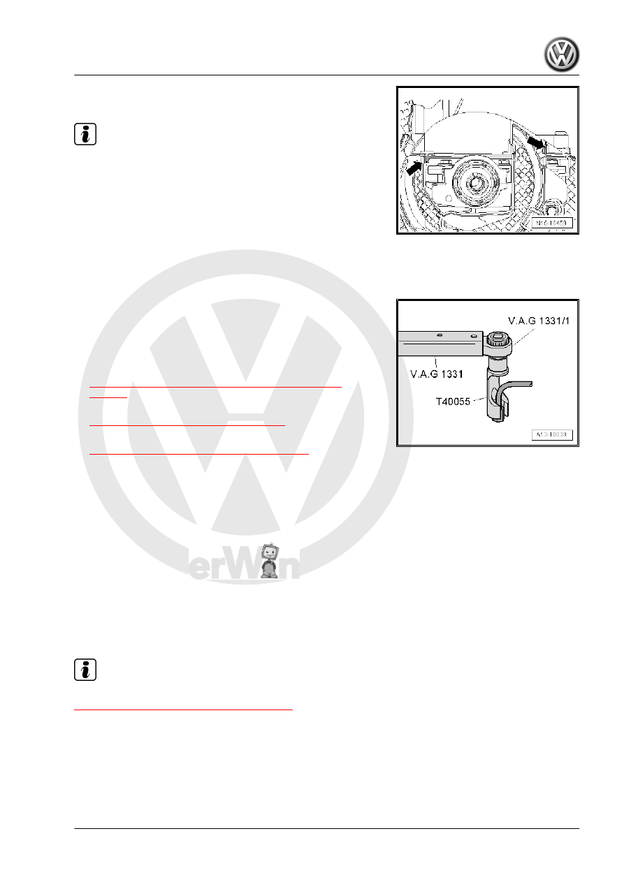
Note

The camshaft is removed here for clarity.

– Press the toothed belt guard upper section near the clips

-arrows- against the cylinder head cover until the clips engage

with each other. Use a screwdriver to press the guard if nec‐

essary.

– Check the clearance between the hub and the toothed belt

guard upper section.

– Tighten the high pressure line union nuts hand-tight.
– Make sure the high pressure line is without tension.

– Tighten the high pressure line using the Torque Wrench 1331

5-50Nm - VAG1331- with Torque Wrench 1331 Insert - Re‐

versible Ratchet - VAG1331/1- and Union Nut Socket -

T40055- .

Tightening Specifications:
• Refer to

⇒ “1.5 Cylinder Head Cover, Removing and Installing”,

page 90

 , Cylinder Head Cover, Removing and Installing

• Overview - Fuel System. Refer to

⇒ “3.3 Overview - Fuel System”, page 311

 .

– Fill the fuel system. Refer to

⇒ “3.9 Fuel System, Filling/Bleeding”, page 328

 .

1.6

Toothed Belt, Removing, Installing and

Tensioning

Special tools and workshop equipment required
♦ Diesel Injection Pump Locking Pin - 3359-
♦ Crankshaft Stop - T10100- or Crankshaft Stop - T10050-
♦ Counterhold - Kit - Multiple Use - T10172-
♦ Wrench - Tensioning Roller - T10264-
♦ Tensioning Roller Locking Tool - T10265-
♦ Torque Wrench 1331 5-50Nm - VAG1331-
♦ Torque Wrench 1332 40-200Nm - VAG1332-

Note

Overview - Toothed Belt Drive. Refer to

⇒ “1.2 Overview - Toothed Belt Drive”, page 43

 .

Removing
Requirements
• Ignition switched off.
• Engine must be cold.

1. Cylinder Head    

95

Adjustments to toothed belt may generally only be performed

when the engine is cold, because the indicator position of the

tensioning element changes depending on engine tempera‐

ture.

The engine bracket must be removed in order to replace the

tensioning roller. Refer to

⇒ “1.7 Engine Bracket, Removing and Installing”, page 52

 .

Procedure
– Remove the engine cover. Refer to

⇒ “1.4 Engine Cover, Removing and Installing”, page 90

 .

– Remove the fuel filter. Refer to

⇒ “6.3 Fuel Filter, Removing and Installing”, page 251

 .

– Remove the Auxiliary Fuel Pump - V393- . Refer to

⇒ “6.6  Auxiliary Fuel Pump V393 (Inline Fuel Pump), Remov‐

ing and Installing”, page 259

 .

– Disconnect the connector -1- from the Engine Coolant Tem‐

perature Sensor on Radiator Outlet - G83- , open the clamps

-arrows- and remove the toothed belt guard upper section.

– Remove the right front wheel housing liner. Refer to ⇒  Body

Exterior; Rep. Gr.  66 ; Wheel Housing Liner .

– Remove the ribbed belt. Refer to

⇒ “1.4 Ribbed Belt, Removing and Installing”, page 47

 .

– Remove the belt pulley/vibration damper -item 29-

⇒ Item 29 (page 45)

 .

– Remove the toothed belt guard lower section and center sec‐

tion -arrows-.

– Remove the nut from the coolant pipe -1-.

96

crankshaft toothed belt gear using the Crankshaft Stop -

T10100- or the Crankshaft Stop - T10050- . Push the crank‐

shaft stop from the front side of the toothed belt gear into the

teeth. The toothed gear must be in the “12 o'clock” position.

Note

The markings on the crankshaft toothed belt sprocket -2- and the

Crankshaft Stop - T10050- -1- must align. The pin on the Crank‐

shaft Stop - T10050- must engage in the hole on the sealing

flange.

– Mark the toothed belt running direction.

– Loosen the camshaft sprocket bolts -1-.

– Loosen the coolant pipe bolt -1- and then the bolts for the fuel

high pressure pump toothed belt sprocket -2-.

– Loosen the tensioning roller nut -1- and turn the tensioning

roller eccentric pulley with the Wrench - Tensioning Roller -

T10264- counter-clockwise in direction of -arrow-, until the

tensioning roller can be locked with the Tensioning Roller

Locking Tool - T10265- .

1. Cylinder Head    

97

rection of -arrow- all the way and tighten the nut -1- by hand.

– First remove the toothed belt from the idler roller and then from

the remaining sprockets.

Installing
Requirements
• Ignition switched off.
• Engine must be cold.
• The tensioning roller must be installed with the Tensioning

Roller Locking Tool - T10265- and the roller must be secured

on the right stop.

• Secure the crankshaft with the Crankshaft Stop - T10100- or

the Crankshaft Stop - T10050- .

Note

Adjustments to toothed belt may generally only be performed

when the engine is cold, because the indicator position of the

tensioning element changes depending on engine tempera‐

ture.

The engine bracket must be removed in order to replace the

tensioning roller. Refer to

⇒ “1.7 Engine Bracket, Removing and Installing”, page 52

 .

Procedure

– Turn the camshaft hub with the Counterhold - Kit - Multiple Use

- T10172- and the Counterhold - Kit - Adapter 4 - T10172/4-

until they can be secured in place. To do so use at least one

bolt -1- tightened by hand.

– Lock the camshaft hub with the Diesel Injection Pump Locking

Pin - 3359- . To do this, push the pin through the empty outer

oblong hole and into the cylinder head hole.

– Loosen the bolts -1-, which were hand-tightened.

98


Content   ..  376  377  378  379   ..