Volkswagen Golf Variant / Jetta. Manual - part 247


  Index      Volkswagen     Volkswagen Golf Variant (2007), Jetta (2005) - service repair manual


Search            


Content   ..  245  246  247  248   ..


Volkswagen Golf Variant / Jetta. Manual - part 247


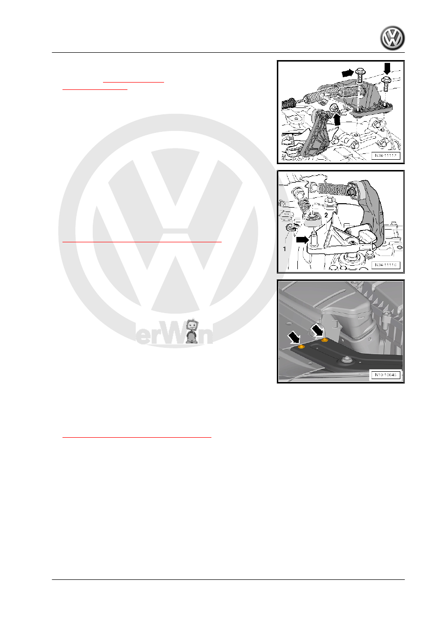
tighten the bolts and nuts -arrows- to the tightening specifica‐

tion -item 6- 

⇒ Item 6 (page 86)

 and -item 10-

⇒ Item 10 (page 86)

 .

– Insert the selector cable into the cable retainer.
– Apply a small amount of grease to the pin -arrow- on the gear‐

shift lever -2-.

Refer to the Parts Catalog for the grease allocation.
– Replace the lock washer -1- after every disassembly.
– Adjust the gearshift mechanism. Refer to

⇒ “1.11 Selector Mechanism, Adjusting”, page 97

 .

– Install the plenum chamber cover. Refer to ⇒  Body Exterior;

Rep. Gr.  50 ; Plenum Chamber Cover; Plenum Chamber

Cover, Removing and Installing .

– Install the bolts -arrows- for the left and right lock carrier re‐

taining brackets to the tightening specification. Refer to ⇒ 

Body Exterior; Rep. Gr.  50 ; Lock Carrier; Lock Carrier - At‐

tachments .

– Install the battery tray and the battery. Refer to ⇒  Electrical

Equipment; Rep. Gr.  27 ; Battery; Battery, Removing and In‐

stalling .

Injection System; Air Filter Housing, Removing and Installing

Installing .

Head; Engine Cover, Removing and Installing .

– Connect the battery and observe procedure after connecting

Battery, Disconnecting and Connecting .

– Check the transmission fluid level. Refer to

⇒ “8 Transmission Fluid, Checking”, page 192

 .

– Install the left front housing liner. Refer to ⇒  Body Exterior;

Rep. Gr.  66 ; Wheel Housing Liner; Front Wheel Housing Lin‐

er, Removing and Installing .

50 ; Noise Insulation .

– Install the wheel. Refer to ⇒  Suspension, Wheels, Steering;

Rep. Gr.  44 ; Wheel Installation Tightening Specifications .

4. Transmission, Removing and Installing, Jetta from MY 11, Diesel and Gasoline    

163

Tightening Specifications

Transmission to Engine (Engine Flange Face)

Item

Bolt

Quantity

Nm

1

M12 x 55

♦ With a short threaded

pin M8 or

M12 x 50

♦ Without threaded pin

1

80

2

M12 x 55

♦ With a long threaded

pin M8

1

80

3

M12 x 70

or M12 x 65

1

80

4

M10 x 50

2

40

5

M10 x 105

1

40

6

M12 x 165

♦ With a short M8 threa‐

ded pin

♦ Also starter to trans‐

mission

1

80

7

M12 x 165

♦ With a short M8 threa‐

ded pin

♦ Also starter to trans‐

mission

1

80

-

M6 x 8

♦ Small flywheel cover

plate (not present on all

engines)

1

10

-A-: Centering alignment sleeves

164

Transmission to Body
– Replace the bolts.
Tighten the bolts -arrows-: 60 Nm + 90°.

Note

Install the engine/transmission mount free of tension. Refer to ⇒ 

Rep. Gr.  10 ; Engine, Removing and Installing .

4. Transmission, Removing and Installing, Jetta from MY 11, Diesel and Gasoline    

165

Transmission, Removing and Instal‐

ling, Jetta from MY 2005 , Golf Wag‐

on from MY 2007 and Golf Wagon

from MY 2010, Vehicles with AWD

⇒ “5.1 Transmission, TDI, Removing and Installing”, page 166

5.1

Transmission, TDI, Removing and In‐

stalling

⇒ “5.1.1 Transmission, Removing”, page 167
⇒ “5.1.2 Transmission, Installing”, page 178
⇒ “5.1.3 Tightening Specifications”, page 186

Special tools and workshop equipment required
♦ Engine Support Bridge - 10-222A-
♦ Engine Support Bridge - Engine Support Feet - 10-222A/8-
♦ Engine Support Bridge - Engine Support 3 - 10-222A/3-
♦ Engine Support Bridge - Engine Support 18 - 10-222A/18-
♦ Transmission Support - 3282-
♦ Support Elements for transmission (determine when mounting

the Mounting Plate on the Transmission Support )

♦ Transmission Support - Mounting Plate 33 - 3282/33-
♦ Transmission Support Jig - 3336- to transport the transmis‐

sion.

♦ Torque Wrench 1331 5-50Nm - VAG1331-
♦ Torque Wrench 1332 40-200Nm - VAG1332-
♦ Engine and Gearbox Jack - VAS6931-
♦ Slide Hammer Set - Adapter 40 - VW771/40-
♦ Hose Clamps - Up To 25mm - 3094-
♦ Engine Support Bridge - Gearbox Bracket - T10346-
♦ Grease for Clutch Disc Shaft Splines - G 000 100-
♦ Allocate the grease for gearshift mechanism. Refer to the

Parts Catalog.

♦ M6 x 80 collar bolt
♦ M10 x 20 hex bolt
The Engine Support Bridge - 10-222A- and the Engine Support

Bridge - Engine Support Feet - 10-222A/8- will be mounted on the

longitudinal members later in the procedure.

166


Content   ..  245  246  247  248   ..