Volkswagen Golf Variant / Jetta. Manual - part 143


  Index      Volkswagen     Volkswagen Golf Variant (2007), Jetta (2005) - service repair manual


Search            


Content   ..  141  142  143  144   ..


Volkswagen Golf Variant / Jetta. Manual - part 143


push the clutch pedal down as far as the spacer.

♦ Spacer length = approximately 40 mm (for example, 

1

/2 socket

insert)

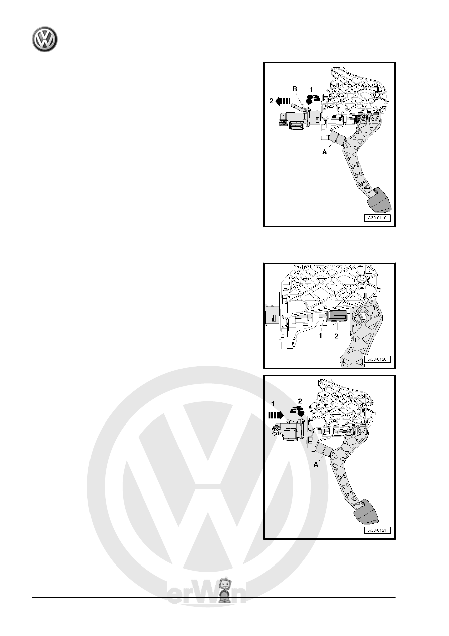
– Unlock the securing clip -B- and remove the clutch master cyl‐

inder from the mounting bracket -arrow 1and arrow 2-.

1.6.2

Installing

• Move the clutch pedal into its rest position.
– Attach the mount -2- to the clutch master cylinder actuator rod

-1-.

– Place a spacer -A- between the clutch pedal and the stop and

push the clutch pedal down as far as the spacer.

♦ Spacer length = approximately 40 mm (for example, 

1

/2 socket

insert)

– Lock the clutch master cylinder to the mounting bracket

-arrow 1 and arrow 2-.

34

-arrow- until the mount -2- audibly engages inside the clutch

pedal.

– Install the mounting bracket. Refer to

⇒ “1.5 Mounting Bracket, Removing and Installing”, page 28

 .

1.7

Clutch Position Sensor - G476- , Re‐

moving and Installing

⇒ “1.7.1 Removing”, page 35
⇒ “1.7.2 Installing”, page 36

1.7.1

Removing

Special tools and workshop equipment required
♦ Hose Clamps - Up To 25mm - 3094-
Perform the following procedure:
– Determine whether a coded radio is installed. If so, obtain the

anti-theft code.

– Disconnect the battery ground cable with the ignition switched

off. Refer to ⇒  Electrical Equipment; Rep. Gr.  27 ; Battery;

Battery, Disconnecting and Connecting .

– Remove the air filter housing if it is located near the battery.

Filter; Air Filter Housing, Removing and Installing .

– Remove the battery and the battery tray. Refer to ⇒  Electrical

Equipment; Rep. Gr.  27 ; Battery; Battery, Removing and In‐

stalling .

If a hose/line assembly -1- with a round component is installed

directly below the clutch master cylinder, hose/line assembly

must be removed.

Note

Be careful not to get any brake fluid on the longitudinal member

or on the transmission when performing the following work. If it

does, clean the areas thoroughly.

1. Clutch Mechanism, Servicing    

35

Hose Clamps - Up To 25mm - 3094- .

– Disengage the clamp -2- using a screwdriver or a pointed tool

and pull the clutch master cylinder out until it stops.

– Disconnect the hose/line assembly -1- or plastic line from the

clutch master cylinder and seal it.

– Disconnect the connector -4-.
– Unclip the Clutch Position Sensor - G476- from the clutch

master cylinder -arrow- and remove it.

1.7.2

Installing

Install in reverse order of removal while. Note the following:

Note

Allocate all components according to the Parts Catalog.

36

on the master cylinder connection -4- until clip -3- audibly

engages.

– Pull on the hose/line assembly or plastic line to make sure it

is secure.

– After removing the Hose Clamps - Up To 25mm - 3094- , return

the hose back to its original shape if necessary.

– Bleed the clutch system. Refer to

⇒ “1.11 Clutch System, Bleeding”, page 44

 .

– Install the battery tray and the battery. Refer to ⇒  Electrical

Equipment; Rep. Gr.  27 ; Battery; Battery, Removing and In‐

stalling .

23 ; Diesel Direct Injection System; Air Filter Housing, Re‐

Housing, Removing and Installing .

– Connect the battery and follow the procedure regarding what

to do after connecting a battery. Refer to ⇒  Electrical Equip‐

ment; Rep. Gr.  27 ; Battery; Battery, Disconnecting and

Connecting .

1.8

Overview - Hydraulics

1. Clutch Mechanism, Servicing    

37


Content   ..  141  142  143  144   ..