Volkswagen Golf / Golf Plus. Manual - part 204
s
p
e
c
t
t
o
th
e
c
o
rr
e
c
t
n
e
s
s
o
f
in
fo
r
m
a
tio
n
in
th
is
d
o
c
um
en
t.
C
o
py
rig
ht b
y
V
olk
sw
a
ge
n
A
G.
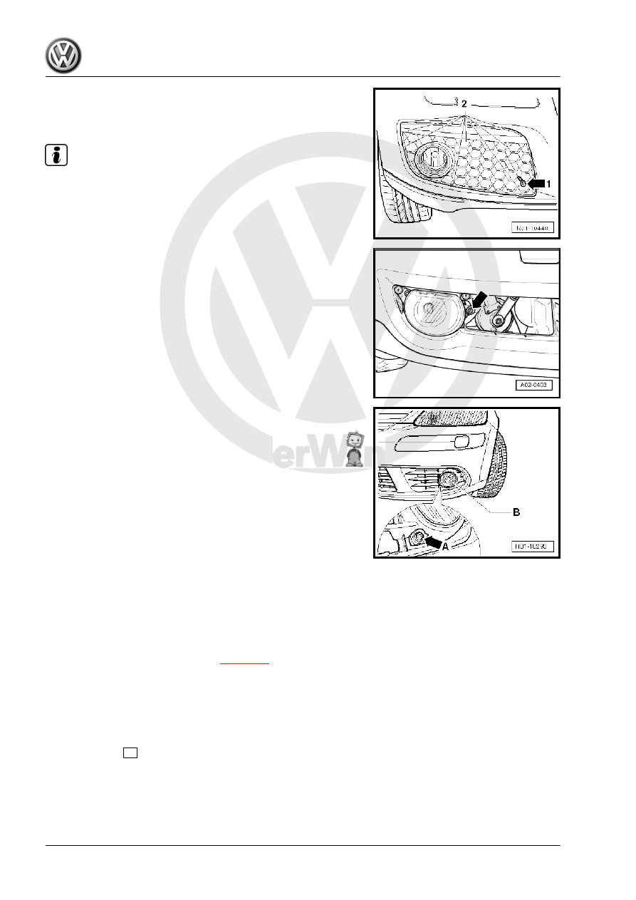
– Remove bolt -1-.
– Unclip retaining lugs -2- and pull cover off lower part of bump‐
er.
Note
In some cases the retaining lugs are very tight. Therefore, pull
cover very carefully to prevent that the retaining lugs break off.
To adjust the headlight range turn adjustment screw -arrow-.
– Secure cover in reverse order.
Fog light in bumper, left (Golf Plus 2005▸)
– To adjust the fog light headlight range -B-, turn adjustment
screw -arrow A-.
Other additional lights
Additionally retrofitted lights of other systems must be checked or
set according to valid guidelines.
4.39
Service interval display: Reset
The service interval display must be reset (adapted) at
♦ delivery inspection
♦ Every service
– Connect vehicle diagnostic tester
.
– Switch on ignition.
– Touch the field or button on the screen for “GUIDED FUNC‐
TIONS”.
If the display is not as shown in the procedure: see operating in‐
structions for vehicle diagnostic tester .
– Confirm with
>
button.
– Select one after the other:
♦ Brand
♦ Type
♦ Model year
Maintenance - Edition 11.2009
126
4. Descriptions of work