Opel Corsa / Vauxhall. Manual - part 7

Fuel and exhaust systems - fuel-injected models 4B•7
11.3a Detach the wiring connector from
11.3b Throttle valve potentiometer removal
11.6a Disconnect the wiring connector . . .
the throttle valve potentiometer
11.6b . . . undo the retaining screw . . .
11.6c . . . and remove the injector
11.11a Detach the wiring connector . . .
12 Refit in the reverse order of removal. To
Pressure regulator
described in Section 6.
avoid damaging the injector housing as the
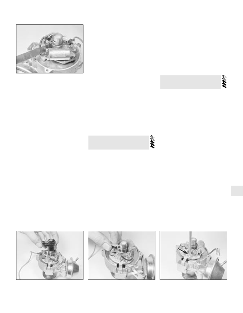
17 Undo the four retaining screws and
16 Prior to removal of the regulator unit, a
motor unit is refitted, press the cone in against
new diaphragm must be obtained as this must
carefully withdraw the regulator unit cover,
its stop and check that the top of the cone to
spring and diaphragm (see illustrations).
be renewed whenever the cover is removed.
the mating flange face is within 28 mm (see
Release the pressure in the fuel system as
18 Refit in the reverse order of removal.
illustration).
Throttle body/injector housing unit
13 Disconnect the wiring connectors from
the throttle body/injector housing.
4B
14 Disconnect the operating rod, then
unscrew and remove the two retaining nuts
from the studs and carefully lift the throttle
body/injector housing from the inlet manifold.
Remove the gasket and clean the mating
surfaces.
15 Refit in the reverse order of removal, but
be sure to fit a new gasket between the
manifold and the throttle body/injector unit.
Tighten the retaining nuts to the specified
11.11b . . . undo the retaining screws . . .
11.11c . . . and remove the idle air stepper
torque setting.
motor
11.12 Idle air stepper motor cone tip-to-
11.17a Undo the retaining screws . . .
11.17b . . . and remove the pressure
flange distance should be as specified
regulator cover, spring and diaphragm

4B•8 Fuel and exhaust systems - fuel-injected models
Ensure that the new diaphragm and its
seatings are clean. Note that no adjustment to
the regulator unit is necessary (or possible).
Inlet manifold pressure sensor
19 This unit is located on the engine side of
the bulkhead. Disconnect the wiring
connector and the vacuum hose, then detach
and remove the unit from the bulkhead.
20 Refit in the reverse order of removal,
ensuring that the vacuum hose and wiring
plug are securely reconnected. Position the
vacuum hose so that it progressively slopes
down between the inlet manifold pressure
12.4 Tightening a throttle valve switch
12.6 Slackening a fuel rail hose clamp
sensor and the throttle housing.
screw
Control unit
Oxygen sensor
withdraw the fuel rail from the injectors (see
illustration). Catch as much fuel as possible.
21 Detach and remove the trim panel from
33 Refer to Section 12, paragraphs 93 to 96.
7 Disconnect the wiring plugs from the
the right-hand footwell to gain access to the
injectors.
control unit.
12 Multi-point fuel injection
8 Unscrew the retaining bolts
(two per
22 Disconnect the wiring multi-plug
system components (1.8 and
injector) and withdraw the injectors from their
connectors, undo the retaining screw then
2.0 litre models) - removal and
holders, being careful not to damage the
release and remove the control unit.
refitting
needle valves (see illustration).
23 The control unit also contains a
9 Refit in the reverse order to removal; renew
programmable memory (PROM) unit in which
the injector sealing rings if their condition is at
the engine/vehicle data and calibration are
1 Disconnect the battery and proceed as
all doubtful.
stored. If this unit is known to be faulty it can
described under the relevant sub-heading.
Later (1990 on) models
be removed from the control unit and
1.8 litre models
10 Refer to paragraphs 5 to 9, noting that the
renewed separately. If the control unit is at
fuel rail is retained by bolts and the injectors
fault, the PROM unit should be removed from
Throttle valve switch
are secured to the fuel rail by clips.
it, the control unit alone renewed and the
2 Disconnect the wiring plug from the switch.
Airflow meter
original PROM unit fitted to the new control
3 Remove the two mounting screws and pull
unit.
11 The airflow meter is located between the
the switch off the throttle valve spindle.
24 To separate the PROM from the control
air cleaner and the throttle valve housing.
4 Refit in the reverse order to removal,
unit, detach and withdraw the cover from the
12 Disconnect the wiring harness plug from
adjusting the switch as follows. Release the
end of the control unit, then press back the
the airflow meter. Release the securing band
switch mounting screws and rotate the switch
retaining clips, unplug and withdraw the
and remove the rubber trunking
(see
in an anti-clockwise direction until resistance
PROM unit from the control unit. When
illustration).
is felt. Tighten the screws (see illustration).
13 Release the spring clips and remove the
removed, no attempt must be made to open
Have an assistant open the throttle valve
airflow meter with the upper part of the air
and/or tamper with the PROM unit. Ensure
slightly by depressing the accelerator pedal. A
cleaner housing.
that its plug contacts are clean and in good
click should be heard from the switch as the
14 Unbolt the airflow meter from the air
condition.
throttle opens; another click should be heard
cleaner housing (see illustration).
25 If renewing the control unit it is important
when the pedal is released..
15 Check the meter flap for free movement,
that the part number/code sticker label is
Fuel injectors
without any jerkiness. If necessary, clean
transferred to the new unit.
away any dirt in the area of the flap using a
26 Refit in the reverse order of the removal
Early (pre 1990) models
clean lint-free rag.
procedure. On completion, switch on the
5 Make sure that the engine is cool, and that
16 Refit in the reverse order to removal.
ignition and check for satisfactory operation.
all sources of external ignition (eg pilot lights)
Control unit
have been extinguished. Disconnect the
Coolant temperature sensor
battery earth lead.
Early (pre 1990) models
27 Partially drain the cooling system to allow
6 Bearing in mind the information given in
17 The control unit is located at the side of
the temperature sensor to be removed
Section
6, release the hose clamps and
the front footwell, on the passenger side.
without excessive coolant loss (Chapter 1).
28 Disconnect the multi-plug from the
temperature sensor, then unscrew the sensor.
Note the position of the sealing ring.
29 Refitting is a reversal of the removal
procedure, using a new sealing ring and
tightening the sensor securely.
Road speed sensor
30 Unclip the road speed sensor multi-plug,
located near the base of the speedometer
cable, and disconnect it. Unscrew and detach
the speedometer cable from the sensor.
31 Unscrew the road speed sensor from its
gearbox location and remove it.
12.8 Undoing a fuel injector retaining bolt
12.12 Disconnecting the airflow meter
32 Refitting is the reverse to removal.
trunking

Fuel and exhaust systems - fuel-injected models 4B•9
12.14 Airflow meter securing bolts
12.36a Removing the control relay and
12.36b Unplugging the control relay
(arrowed)
bracket
18 Remove the footwell trim panel.
temperature gauge sensor, it is known as
37 Refit in the reverse order to removal.
19 Make sure that the ignition is switched off,
temperature sensor ll.
Fuel pressure regulator
then release the multi-plug spring clip and
26 Partially drain the cooling system - about
38 The fuel pressure regulator is located
disconnect the multi-plug.
3 litres should be sufficient.
between injectors 3 and 4 (see illustration).
20 Remove the three securing screws and
27 Disconnect the electrical lead and
39 Disconnect the battery earth lead and
withdraw the control unit.
unscrew the sensor.
take appropriate fire precautions.
21 Refit in the reverse order to removal, but
28 Refit in the reverse order to removal. Use
40 Clamp the fuel hoses to minimise fuel
make sure that the ignition is switched off
a little sealant on the sensor threads, and refill
loss, using self-locking grips with suitably
before reconnecting the multi-plug.
the cooling system on completion.
protected jaws.
Later (1990 on) models
Auxiliary air valve
41 Disconnect the fuel and vacuum hoses
22 Remove the airflow meter as described
29 The auxiliary air valve is bolted to the side
form the pressure regulator and remove it. Be
earlier.
of the camshaft housing.
prepared for fuel spillage.
23 Remove the four screws which secure the
30 Disconnect the wiring plug from the valve.
42 Refit in the reverse order to removal.
cover to the top of the airflow meter (these
31 Release the hose clips and disconnect the
may be hidden by blanking plugs). Remove
2.0 litre models
air hoses from the valve.
the cover and insert, then the control unit.
32 Unbolt and remove the valve.
43 Refer to the information given earlier for
24 Refitting is the reverse of removal.
33 The function of the valve may be checked
the 1.8 litre models, information for additional
Coolant temperature sensor
by looking through the hose connecting
components is as follows
25 The coolant temperature sensor for the
stubs. A clear passage should exist between
Idle speed adjuster
fuel injection system is located near the
the stubs when the valve is cold. As the valve
44 Note the routing and positioning of the air
alternator. Because it is additional to the
is heated
(achieved by connecting its
hoses, then disconnect the multi-plug and the
terminals to a 12 volt battery) the regulator
air hoses from the idle speed adjuster (see
disc should move round and block the hole.
illustrations). On the 16-valve engine the
34 Refit in the reverse order to removal, using
adjuster is located below the inlet manifold;
4B
new hose clips if necessary. An air leak on the
access is not good but is easier from below.
intake side of the valve will raise the idle speed.
45 Refitting is the reverse of the removal
Control relay
procedure.
35 The control relay is located on the front
Control unit
suspension strut turret. Unplugging the relay
46 The control unit is located behind the side
disables the fuel pump - this is necessary
trim panel in the driver’s footwell. To remove
when performing a compression test.
the trim panel, first remove the front two
36 Slacken the securing bolt, remove the
screws from the driver’s ‘kick plate’ and peel
relay and its bracket from the turret, and
back the door surround strip in the area next
withdraw the relay from the plug
(see
to the side trim panel (see illustrations).
12.38 Fuel pressure regulator
illustrations).
12.44a Disconnect the idle speed adjuster
12.44b . . . and the air hoses (arrowed)
12.46a Remove the kick plate screws . . .
multi-plug . . .

4B•10 Fuel and exhaust systems - fuel-injected models
12.46b . . . and peel back the door
12.47 Prise out the clips to release the trim
12.48 Motronic control unit location
surround strip
panel
47 Open the access panel in the side trim.
injectors to the fuel rail by prising them out.
63 Disconnect the multi-plugs from the air
Prise out the plastic retaining clips and
55 Disconnect the brake servo hose from the
mass meter and from the throttle valve switch.
withdraw the side trim panel
(see
throttle body housing.
64 Unbolt the throttle cable bracket and
illustration).
56 Unbolt the fuel supply hose bracket.
move it aside.
48 Remove the retaining screws to release
57 Carefully lift the fuel rail away from the
65 Remove the nuts securing the earth straps
the control unit (see illustration). Release the
manifold and pull out the injectors.
at each end of the fuel rail (see illustration).
multi-plug catch and disconnect the
58 Refitting is the reverse of the removal
66 The injector multi-plugs must now be
multi-plug. Handle the control unit with care if
procedure. If the old injectors are being
disconnected. Each plug is secured by a
it is to be re-used.
refitted, use new sealing rings.
spring clip, which must be levered out with a
49 Refitting is the reverse of the removal
small screwdriver or long-nosed pliers. With
Fuel injectors - Motronic M2.5
procedure.
all the multi-plugs released, cut or undo cable
59 Remove the pre-volume chamber as
Inductive pulse sensor
ties as necessary and move the wiring rail
described earlier.
forwards so that it rests on the camshaft
50 Refer to Chapter 5.
60 Bearing in mind the information in Section
cover (see illustrations).
6, clean around the unions on the fuel rail, then
Fuel injectors - Motronic ML4.1 and
67 Remove the two bolts which secure the
disconnect the supply and return hoses from it
M1.5
fuel rail to the inlet manifold.
(see illustration). Be prepared for fuel spillage.
51 Remove the idle speed adjuster.
68 Pull the rail and injectors away from the
61 Disconnect the two crankcase ventilation
52 Disconnect the wiring plugs from the fuel
manifold.
hoses from the camshaft cover. To improve
injectors.
access, remove the larger of the two hoses
69 Individual injectors may now be removed
53 Unbolt the fuel rail from the inlet manifold,
completely.
from the rail by removing their retaining clips
bearing in mind the information in Section 6.
62 Disconnect the vacuum hose from the fuel
and pulling them from the rail
(see
54 Remove the clips which secure the
pressure regulator.
illustrations).
12.60 Disconnecting the fuel supply line
12.65 One of the earth straps on the fuel
12.66a Removing the spring clip from an
from the fuel rail
rail
injector multi-plug
12.66b Lifting the wiring rail off the
12.69a Remove the retaining clip
12.69b . . . and pull out the injector
injectors

Fuel and exhaust systems - fuel-injected models 4B•11
12.73 Disconnecting the fuel return line
12.74 Disconnecting the vacuum hose
12.77 Removing a pre-volume chamber
from the fuel pressure regulator
screw
70 Refitting is the reverse of the removal
75 Remove the four Torx screws which
83 Refitting is the reverse of the removal
procedure. If the old injectors are being
secure the pressure regulator to the fuel rail. A
procedure. Adjust the switch before tightening
refitted, use new sealing rings.
small E6 Torx spanner will be needed for
the screws as described in paragraph 4 of this
access to the screws. If this is not available
Section.
Throttle valve potentiometer -
the fuel rail will have to be removed so that the
Motronic M1.5
Air mass meter - Motronic M2.5
screws can be undone with a socket or (at a
71 The throttle valve potentiometer is
pinch) self-locking pliers. With the screws
84 Disconnect the multi-plug from the air
removed and refitted in the same way as the
removed, the pressure regulator can be
mass meter (see illustration).
throttle valve switch (which it replaces) on
removed from the rail.
85 Release the hose clips from each end of the
earlier models. There is no need for
76 Refitting is the reverse the removal.
meter and remove it. Do not drop it, it is fragile.
adjustment.
Pre-volume chamber - Motronic M2.5
86 Refitting is the reverse of the removal
procedure.
Fuel pressure regulator - Motronic
77 Remove the four Allen screws which
M1.5 and 2.5
Coolant temperature sensor -
secure the pre-volume chamber to the throttle
Motronic M2.5
72 On Motronic M2.5 systems, remove the
housing (see illustration). On some models
pre-volume chamber.
there is a fifth screw to the left which must
87 Partially drain the cooling system at the
73 Bearing in mind the information in Section 6,
also be removed.
radiator bottom hose to bring the coolant level
disconnect the fuel return union from the
78 Release the hose clip which secures the
below the level of the thermostat housing.
pressure regulator
(see illustration). Be
air mass meter to the pre-volume chamber.
88 Disconnect the multi-plug from the sensor
prepared for fuel spillage.
79 Lift the pre-volume chamber slightly and
on the thermostat housing. The Motronic
74 Disconnect the vacuum hose from the
disconnect the idle speed adjuster hose from
sensor is the larger of the two the smaller one
regulator (see illustration).
the left-hand end (see illustration). Remove
feeds the temperature gauge. Unscrew the
the pre-volume chamber.
sensor and remove it.
80 Refitting is the reverse of the removal
89 Refitting is the reverse of the removal
procedure, but note that it is important that
procedure, noting the following points:
the ring which seals the throttle body to the
a) Use a new sealing ring on the sensor, and
4B
pre-volume chamber is not displaced during
apply a little sealant to its threads.
fitting. Air leaks at this point will weaken the
b) Refill the cooling system as described in
mixture and dirt may enter. Secure the ring to
Chapter 1.
the chamber if necessary with a few dabs of
Knock sensor - Motronic M2.5
sealant (see illustration).
90 The knock sensor is on the rear of the
Throttle valve switch - Motronic M 2.5
cylinder block. Unless the inlet manifold has
81 Remove the pre-volume chamber and the
been removed, access is easiest from below.
air mass meter.
91 Disconnect the multi-plug (coloured red or
82 Disconnect the multi-plug from the switch
orange) from the knock sensor. Remove the
(see illustration). Remove the two screws
securing screw and the sensor
(see
12.79 Idle speed adjuster hose attachment
and withdraw the switch.
illustration).
to pre-volume chamber
12.80 Pre-volume chamber sealing ring
12.82 Disconnecting the throttle valve
12.84 Disconnecting the multi-plug from
switch multi-plug
the air mass meter

4B•12 Fuel and exhaust systems - fuel-injected models
12.91 Knock sensor multi-plug (arrowed)
12.94 Disconnecting the oxygen sensor
12.95 Removing the oxygen sensor
seen from below
multi-plug
12.98a Canister clamp nut (arrowed)
12.98b Disconnecting a hose from the
12.100 Disconnecting the vent valve
canister
multi-plug
92 Refitting is the reverse of the removal
hoses from it and remove it
(see
e) Auxiliary air valve (see illustration).
procedure, but make sure that the sensor and
illustrations). Treat the canister with the
f) Cam cover earth tags.
its seat are perfectly clean and that the sensor
same precautions as would apply to a fuel
4 Disconnect the distributor vacuum hose
is secured firmly. Failure to observe these
tank - it may be full of vapour.
from the throttle valve housing
(see
points could lead to damage to the engine,
99 Refitting is the reverse of the removal
illustration).
because a poorly mounted sensor will not
procedure.
5 Depressurise the cooling system by
pick up knocking
(pinking) and the
unscrewing the expansion tank cap, taking
Vent valve - 16-valve models with a
appropriate ignition correction will not be
precautions against scalding if the system is
catalytic converter
applied.
hot. Disconnect and plug the coolant hoses
100 Disconnect the multi-plug and the hoses
from the throttle valve housing.
Oxygen sensor - models with a
from the vent valve (see illustration). Unbolt
6 Disconnect the air inlet duct from the
catalytic converter
the valve bracket and remove the valve and
housing.
93 Bring the engine to operating
bracket.
7 Disconnect the brake servo and crankcase
temperature, then switch it off and disconnect
101 Refitting is the reverse of the removal
ventilation hoses from the housing.
the battery.
procedure.
8 Disconnect and plug the fuel hoses from
94 Disconnect the oxygen sensor multi-plug,
the fuel rail stubs. The hoses are different
which is located near the right-hand
13 Inlet manifold - removal and
sizes and one of them carries a white band for
suspension turret (see illustration). Free the
refitting
identification. Be prepared for fuel spillage.
wiring leading to the sensor.
9 Disconnect the accelerator cable from the
95 Working under the vehicle, unscrew the
throttle levers. The cable inner is secured by a
sensor from the exhaust manifold
(see
Removal
illustration).
96 Refitting is the reverse of the removal
1.4 and 1.6 litre models
procedure. Note that the makers specify the
1 Refer to the information given in Section 11,
use of a special anti-seize compound made of
Chapter 4A, for information on the various
graphite and glass beads. New sensors are
electrical components which must be
provided with their threads already coated
disconnected.
with this compound. When refitting a used
1.8 litre models
sensor, obtain some of the special compound
from a Vauxhall dealer.
2 Disconnect the battery earth lead.
3 Disconnect the injection wiring harness
Carbon canister - 16-valve models
plugs and earth connections as follows:
with a catalytic converter
a) Airflow meter plug.
97 Raise the front of the vehicle and remove
b) Coolant temperature sensor (see
the left-hand roadwheel.
illustration).
13.3a Coolant temperature sensor plug
98 Slacken the canister clamp nut. Release
c) Fuel injectors (see illustration).
(arrowed)
the canister from the clamp, disconnect the
d) Throttle valve switch (see illustration).

Fuel and exhaust systems - fuel-injected models 4B•13
13.3b Disconnecting a fuel injector plug
13.3c Unplugging the throttle valve switch
13.3d Unplugging the auxiliary air valve
lead connector
wire clip, and the outer is retained in its
adjuster strap nut and bolt (see Chapter 1).
24 Bearing in mind the information given in
bracket by an E-clip (see illustration).
17 Disconnect the throttle cable from the
Section 6, disconnect the fuel supply and
10 Unscrew the nuts which secure the inlet
throttle housing. Pull the cable out of the
return unions from the fuel rail. Be prepared
manifold to the cylinder head. The lower nuts
retainer and move it aside (see illustration).
for fuel spillage.
are different to reach: a small socket or ring
18 Remove the 9 nuts which secure the
25 Release the fuel supply hose bracket from
spanner will be needed.
manifold to the cylinder head. These are all
the throttle housing.
11 Lift away the manifold and recover the
stiff and some are not easily accessible; a
26 Release the cable tie which secures the
gasket (see illustrations).
socket with a “wobble drive” or universal joint
coolant hoses to the right-hand side of the
will be needed. Once the nuts are removed,
manifold.
2.0 litre 8-valve models
slide the manifold back on its studs to
27 Disconnect the brake servo vacuum hose
12 Refer to the information given above in
improve access to the injector wiring rail.
and the large coolant hose from the base of
paragraphs
2 to
11, noting the hose
19 Disconnect the two breather hoses from
the manifold (see illustrations).
connections shown (see illustration).
the camshaft cover.
28 Unhook the clutch cable from the bracket
2.0 litre 16-valve models
20 Disconnect the injector wiring rail from the
behind the manifold.
13 Disconnect the battery earth (negative)
injectors as described earlier.
29 Disconnect the small coolant hose from
lead.
21 Release the earth straps from each end of
the expansion tank.
14 Drain the cooling system (see Chapter 1).
the fuel rail.
30 Disconnect the air hose which connects
15 Remove the pre-volume chamber, the air
22 If a vent valve is fitted, disconnect the
the idle speed adjuster to the base of the
mass meter and its trunking as described in
multi-plug and the hose from it.
manifold.
Section 12.
23 Disconnect the throttle position switch
31 With the help of an assistant, lift the
16 Remove the alternator drivebelt and the
multi-plug.
manifold to gain access to the idle speed
4B
13.9 Accelerator cable at engine end
13.4 Distributor vacuum hose (A), coolant
13.11a Removing the inlet manifold -
hose (B) and breather (C) on throttle housing
1.8 litre model
13.12 Throttle valve housing - ML4.1
A Hose from idle speed adjuster
B Crankcase ventilation hose
13.11b Inlet manifold showing injectors
C Coolant hose
13.17 Pulling the throttle cable out of the
fuel rail and associated components
D Coolant hose
retainer

4B•14 Fuel and exhaust systems - fuel-injected models
13.27a Disconnect the brake servo
13.27b . . . and the large coolant hose
13.32 Removing the inlet manifold - 2. litre
hose . . .
16-valve model
adjuster and the knock sensor. Disconnect
b) Tighten the manifold nuts to the specified
support bracket (see illustration).
the multiplugs from these components and
torque.
6 Lift away the manifold and recover the
feed the wiring harness back through the
c) Refill and bleed the cooling system as
gasket.
manifold.
described in Chapter 1.
All other models
32 Remove the manifold complete with fuel
7 Refer to Chapter 4A. On models with an
rail and injectors (see illustration). Recover
14 Exhaust manifold - removal
oxygen sensor, disconnect the sensor multi-
the gasket.
and refitting
plug and free the wiring to prevent it being
Refitting
strained whilst the manifold is removed.
33 Refitting is the reverse of the removal
Removal
Refitting
procedure, noting the following points:
8 Refitting is the reverse of the removal
a) Use a new manifold gasket (see
2.0 litre 16-valve models
procedure, using a new manifold gasket (see
illustration).
1 Raise and securely support the front of the
illustration).
vehicle (see “Jacking and Vehicle Support”).
2 Disconnect the battery earth
(negative)
15 Exhaust system - inspection,
lead.
3 Remove the manifold heat shield, which is
removal and refitting
secured by three bolts at the top and two of
the manifold nuts at the bottom
(see
1 Refer to Chapter 4A. On models with an
illustration).
oxygen sensor, it will be necessary to
4 Remove the remaining
10 nuts which
disconnect the sensor multi-plug and free the
secure the manifold.
wiring from its retaining clips before removal.
5 On models with an oxygen sensor,
On refitting ensure the sensor wiring is
disconnect the sensor multiplug (near the
correctly routed and in no danger of
right-hand suspension mounting) and free the
contacting the exhaust system.
wiring leading to the sensor.
13.33 Fitting a new inlet manifold gasket
5 Working under the vehicle, unbolt the
manifold-to-exhaust system flexible joint and
14.3 Removing an exhaust manifold heat
14.5 Manifold-to-exhaust system joint and
14.8 Fitting a new exhaust manifold gasket
shield bolt
bracket

5A•1
Chapter 5 Part A:
Starting and charging systems
Contents
Alternator - removal and fitting
7
General information and precautions
1
Alternator - testing and overhaul
8
Ignition switch - removal and refitting
12
Alternator drivebelt - removal, refitting and tensioning
6
Oil level sensor (16-valve models) - removal and refitting
14
Battery - removal and refitting
4
Oil pressure warning light switch/gauge sender - removal and
Battery - testing and charging
3
refitting
13
Battery check
See Chapter 1
Starter motor - removal and refitting
10
Charging system - testing
5
Starter motor - testing and overhaul
11
Electrical fault finding - general information
2
Starting system - testing
9
Electrical system check
See Chapter 1
Degrees of difficulty
Easy, suitable for
Fairly easy, suitable
Fairly difficult,
Difficult, suitable for
Very difficult,
novice with little
for beginner with
suitable for competent
experienced DIY
suitable for expert
experience
some experience
DIY mechanic
mechanic
DIY or professional
Specifications
System type
12V negative earth
Battery
Capacity
36 to 66 Ah (depending on model)
Charge condition:
Poor
12.5 volts
Normal
12.6 volts
Good
12.7 volts
Alternator
Type
Bosch or Delco
Output
45, 55 or 65A (depending on model)
Starter motor
Type
Pre-engaged Bosch or Delco
5A
Torque wrench settings
Nm
lbf ft
Alternator mounting bracket bolts*
40
30
Alternator pivot and adjustment bolts*
34
25
Starter motor mounting bolts*:
1.3 litre models
25
18
1.6, 1.8 and 2.0 litre models
45
33
*Torque wrench settings for the 1.2 litre models not available
The battery is of the low maintenance or
While some repair procedures are given, the
1 General information and
“maintenance-free” (sealed for life) type and is
usual course of action is to renew the
precautions
charged by the alternator, which is belt-driven
component concerned. The owner whose
from the crankshaft pulley.
interest extends beyond mere component
The starter motor is a pre-engaged type
renewal should obtain a copy of the
General information
incorporating an integral solenoid. On starting,
“Automobile Electrical & Electronic Systems
The engine electrical system consists
the solenoid moves the drive pinion into
Manual”, available from the publishers of this
mainly of the charging and starting systems.
engagement with the flywheel ring gear before
manual.
Because of their engine-related functions,
the starter motor is energised. Once the
It is necessary to take extra care when
these components are covered separately
engine has started, a one-way clutch prevents
working on the electrical system to avoid
from the body electrical devices such as the
the motor armature being driven by the engine
damage to semi-conductor devices (diodes
lights, instruments, etc (which are covered in
until the pinion disengages from the flywheel.
and transistors), and to avoid the risk of
Chapter
12). Refer to Part B or C for
personal injury. In addition to the precautions
information on the ignition system.
Precautions
given in the “Safety first!” section of this
The electrical system is of the
12-volt
Further details of the various systems are
manual, observe the following when working
negative earth type.
given in the relevant Sections of this Chapter.
on the system:

5A•2 Starting and charging systems
Always remove rings, watches, etc before
or deterioration of the internal plates.
Standard and low maintenance
working on the electrical system. Even with
3 If the specific gravity variation is 0.040 or
battery - charging
the battery disconnected, capacitive
more, the battery should be renewed. If the
Note: The following is intended as a guide
discharge could occur if a component’s live
cell variation is satisfactory but the battery is
only. Always refer to the manufacturer’s
terminal is earthed through a metal object.
discharged, it should be charged as
recommendations (often printed on a label
This could cause a shock or nasty burn.
described later in this Section.
attached to the battery) before charging a
Do not reverse the battery connections.
Maintenance-free battery -
battery.
Components such as the alternator, electronic
testing
9 Charge the battery at a rate of 3.5 to 4
control units, or any other components having
amps and continue to charge the battery at
semi-conductor circuitry could be irreparably
4 In cases where a
“sealed for life”
this rate until no further rise in specific gravity
damaged.
maintenance-free battery is fitted, topping-up
is noted over a four hour period.
If the engine is being started using jump
and testing of the electrolyte in each cell is not
10 Alternatively, a trickle charger charging at
leads and a slave battery, connect the
possible. The condition of the battery can
the rate of
1.5 amps can safely be used
batteries positive-to-positive and negative-to-
therefore only be tested using a battery
overnight.
negative
(see
“Booster battery
(jump)
condition indicator or a voltmeter.
11 Specially rapid `boost’ charges which are
starting”). This also applies when connecting
5 A Delco type maintenance-free battery is
claimed to restore the power of the battery in
a battery charger.
fitted with a built-in charge condition
1 to 2 hours are not recommended, as they
Never disconnect the battery terminals, the
indicator. The indicator is located in the top of
can cause serious damage to the battery
alternator, any electrical wiring or any test
the battery casing, and indicates the condition
plates through overheating.
instruments when the engine is running.
of the battery from its colour. If the indicator
12 While charging the battery, note that the
Do not allow the engine to turn the
shows green, then the battery is in a good
temperature of the electrolyte should never
alternator when the alternator is disconnected.
state of charge. If the indicator turns darker,
exceed 37.8ºC (100ºF).
Never
“test” for alternator output by
eventually to black, then the battery requires
‘flashing’ the output lead to earth.
charging, as described later in this Section. If
Maintenance-free battery -
Never use an ohmmeter of the type
the indicator shows clear/yellow, then the
charging
incorporating a hand-cranked generator for
electrolyte level in the battery is too low to
Note: The following is intended as a guide
circuit or continuity testing.
allow further use, and the battery should be
only. Always refer to the manufacturer’s
Always ensure that the battery negative
renewed. Do not attempt to charge, load or
recommendations (often printed on a label
lead is disconnected when working on the
jump start a battery when the indicator shows
attached to the battery) before charging a
electrical system.
clear/yellow (see illustration).
battery.
Before using electric-arc
welding
6 If testing the battery using a voltmeter,
13 This battery type takes considerably
equipment on the car, disconnect the battery,
connect the voltmeter across the battery and
longer to fully recharge than the standard
alternator and components such as the fuel
compare the result with those given in the
type, the time taken being dependent on the
injection/ignition electronic control unit to
Specifications under “charge condition”. The
extent of discharge, but it can take anything
protect them from the risk of damage.
test is only accurate if the battery has not
up to three days.
been subjected to any kind of charge for the
14 A constant voltage type charger is
previous six hours. If this is not the case,
2 Electrical fault finding - general
required, to be set, when connected, to 13.9
switch on the headlights for 30 seconds, then
to 14.9 volts with a charger current below 25
information
wait four to five minutes before testing the
amps. Using this method, the battery should
battery after switching off the headlights. All
be usable within three hours, giving a voltage
Refer to Chapter 12.
other electrical circuits must be switched off,
reading of 12.5 volts, but this is for a partially
so check that the doors and tailgate are fully
discharged battery and, as mentioned, full
shut when making the test.
charging can take considerably longer.
3 Battery - testing and charging
7 If the voltage reading is less than 12.2 volts,
15 If the battery is to be charged from a fully
then the battery is discharged, whilst a
discharged state (condition reading less than
reading of
12.2 to
12.4 volts indicates a
12.2 volts), have it recharged by your Vauxhall
Standard and low maintenance
partially discharged condition.
dealer or local automotive electrician, as the
battery - testing
8 If the battery is to be charged, remove it
charge rate is higher and constant supervision
from the vehicle (Section 4) and charge it as
1 If the vehicle covers a small annual mileage
during charging is necessary.
described later in this Section.
it is worthwhile checking the specific gravity
of the electrolyte every three months to
determine the state of charge of the battery.
Use a hydrometer to make the check and
compare the results with the following table.
Note that the specific gravity readings assume
an electrolyte temperature of 15ºC (60ºF); for
every 10ºC (48ºF) below 15ºC (60ºF) subtract
0.007. For every 10ºC (48ºF) above 15ºC
(60ºF) add 0.007.
Ambient temperature, 25ºC (77ºF)
above
below
Fully-charged
1.21 to 1.23
1.27 to 1.29
70% charged
1.17 to 1.19
1.23 to 1.25
Fully-discharged
1.05 to 1.07
1.11 to 1.13
2 If the battery condition is suspect, first
check the specific gravity of electrolyte in
each cell. A variation of
0.040 or more
between any cells indicates loss of electrolyte
3.5 Battery condition indicator on maintenance-free type battery

Starting and charging systems 5A•3
brushes at a reasonable cost. However, check
on the cost of repairs before proceeding as it
4 Battery - removal and refitting
may prove more economical to obtain a new
or exchange alternator.
Removal
1 The battery is located on the left-hand side
9 Starting system - testing
of the engine bay.
2 Slacken the clamp nut and bolt on the
Note: Refer to the precautions given in
negative (-) terminal clamp (see illustration).
“Safety first!” and in Section 1 of this Chapter
Lift the clamp off the terminal post. If the
before starting work.
clamp is stuck to the post, beware of using
1 If the starter motor fails to operate when the
force to free it as the post may be broken.
4.2 Disconnect the battery negative
ignition key is turned to the appropriate
Warm water will usually do the trick.
terminal first
position, the following possible causes may
3 Similarly disconnect the positive (+) terminal;
be to blame.
this may be protected by a plastic cover.
7 If the regulated voltage is not as stated, the
a) The battery is faulty.
4 Undo the clamp bolt at the base of the
fault may be due to worn brushes, weak brush
b) The electrical connections between the
battery and lift out the battery. Be careful, it is
springs, a faulty voltage regulator, a faulty
switch, solenoid, battery and starter
heavy. Keep it upright and do not drop it.
diode, a severed phase winding or worn or
motor are somewhere failing to pass the
damaged slip rings. The alternator should be
Refitting
necessary current from the battery
renewed or taken to an auto-electrician for
through the starter to earth.
5 Refit in the reverse order to removal,
testing and repair.
c) The solenoid is faulty.
connecting the earth (negative) lead last. Use
d) The starter motor is mechanically or
a little proprietary anti-corrosion compound,
6 Alternator drivebelt - removal,
electrically defective.
or petroleum jelly, on the terminal posts. Do
refitting and tensioning
2 To check the battery, switch on the
not overtighten the clamp bolt or the terminal
headlights. If they dim after a few seconds,
clamps.
Refer to the procedure given for the
this indicates that the battery is discharged -
auxiliary drivebelt(s) in Chapter 1.
recharge (see Section 3) or renew the battery.
If the headlights glow brightly, operate the
5 Charging system - testing
ignition switch and observe the lights. If they
7 Alternator - removal and
dim, then this indicates that current is
Note: Refer to the warnings given in “Safety
refitting
reaching the starter motor, therefore the fault
first!” and in Section 1 of this Chapter before
must lie in the starter motor. If the lights
starting work.
continue to glow brightly (and no clicking
Removal
1 If the ignition warning light fails to illuminate
sound can be heard from the starter motor
1 Disconnect the battery earth
(negative)
when the ignition is switched on, first check
solenoid), this indicates that there is a fault in
the alternator wiring connections for security.
lead.
the circuit or solenoid
- see following
2 Make a note of the electrical connections at
If satisfactory, check that the warning light
paragraphs. If the starter motor turns slowly
bulb has not blown, and that the bulbholder is
the rear of the alternator, then disconnect the
when operated, but the battery is in good
multi-plug, spade terminals or other
secure in its location in the instrument panel.
condition, then this indicates that either the
connectors as appropriate.
If the light still fails to illuminate, check the
starter motor is faulty, or there is considerable
3 Remove the alternator strap bolts, noting
continuity of the warning light feed wire from
resistance somewhere in the circuit.
the short earth lead which links the alternator
5A
the alternator to the bulbholder. If all is
3 If a fault in the circuit is suspected,
to the engine. Slacken the pivot bolt, swing
satisfactory, the alternator is at fault and
disconnect the battery leads (including the
the alternator towards the engine and remove
should be renewed or taken to an auto-
earth connection to the body), the
the drivebelt.
electrician for testing and repair.
starter/solenoid
wiring
and
the
4 Remove the pivot bolt and lift off the
2 If the ignition warning light illuminates when
engine/transmission earth strap. Thoroughly
alternator. On one car examined, the pivot
the engine is running, stop the engine and
clean the connections, and reconnect the
bolt had been inserted from the ‘wrong’ side
check that the drivebelt is correctly tensioned
leads and wiring, then use a voltmeter or test
so that it could not be withdrawn far enough
(see Chapter
1) and that the alternator
lamp to check that full battery voltage is
to release the alternator: in this case it is
connections are secure. If all is so far
available at the battery positive lead
necessary to unbolt the alternator mounting
satisfactory, have the alternator checked by
connection to the solenoid, and that the earth
from the block.
an auto-electrician for testing and repair.
is sound. Smear petroleum jelly around the
5 Take care not to knock or drop the
3 If the alternator output is suspect even
battery terminals to prevent corrosion
-
alternator.
though the warning light functions correctly, the
corroded connections are amongst the most
regulated voltage may be checked as follows.
Refitting
frequent causes of electrical system faults.
4 Connect a voltmeter across the battery
4 If the battery and all connections are in
6 Refit in the reverse order to removal; tension
terminals and start the engine.
good condition, check the circuit by
the drivebelt as described in Chapter 1.
5 Increase the engine speed until the
disconnecting the wire from the solenoid
voltmeter reading remains steady; the reading
blade terminal. Connect a voltmeter or test
should be approximately 12 to 13 volts, and
lamp between the wire end and a good earth
8 Alternator - testing and overhaul
no more than 14 volts.
(such as the battery negative terminal), and
6 Switch on as many electrical accessories
check that the wire is live when the ignition
(eg, the headlights, heated rear window and
If the alternator is thought to be suspect, it
switch is turned to the `start’ position. If it is,
heater blower) as possible, and check that the
should be removed from the vehicle and taken
then the circuit is sound - if not the circuit
alternator maintains the regulated voltage at
to an auto-electrician for testing. Most auto-
wiring can be checked as described in
around 13 to 14 volts.
electricians will be able to supply and fit
Chapter 12.

5A•4 Starting and charging systems
5 The solenoid contacts can be checked by
2.0 litre 16-valve models
2 Disconnect the battery negative lead and
connecting a voltmeter or test lamp between
8 Remove the starter motor-to-transmission
disconnect the wiring from the switch/sender
the battery positive feed connection on the
bolts which are accessible from above.
(see illustration).
starter side of the solenoid, and earth. When
9 Raise and support the front of the vehicle
3 Unscrew the switch/sender and recover the
the ignition switch is turned to the `start’
(see “Jacking and Vehicle Support”). Remove
sealing washer. Be prepared for oil spillage,
position, there should be a reading or lighted
the inlet manifold bracing strap.
and if the switch is to be left removed from the
bulb, as applicable. If there is no reading or
10 Disconnect the main feed and command
engine for any length of time, plug the hole.
lighted bulb, the solenoid is faulty and should
leads from the starter motor.
11 Remove the remaining starter motor
Refitting
be renewed.
mounting bolts, not forgetting the bracket at
6 If the circuit and solenoid are proved
4 Examine the sealing washer for signs of
the brushgear end of the motor. Remove the
sound, the fault must lie in the starter motor.
damage or deterioration and if necessary
motor from below.
In this event, it may be possible to have the
renew.
starter motor overhauled by a specialist, but
Refitting
5 Refit the switch/sender, complete with
check on the cost of spares before
washer, and tighten it securely. Reconnect the
12 Refitting is the reverse of the removal
proceeding, as it may prove more economical
wiring.
procedure.
to obtain a new or exchange motor.
6 Check and, if necessary, top-up the engine
oil as described in Chapter 1.
11 Starter motor - testing and
10 Starter motor - removal and
overhaul
refitting
14 Oil level sensor (16-valve
If the starter motor is thought to be suspect,
models) - removal and refitting
it should be removed from the vehicle and
Removal
taken to an auto-electrician for testing. Most
1 Disconnect the battery earth lead.
Removal
auto-electricians will be able to supply and fit
1.2 litre models
brushes at a reasonable cost. However, check
1 Raise and support the front of the vehicle
on the cost of repairs before proceeding as it
(see “Jacking and Vehicle Support”).
2 Disconnect the battery positive leads;
may prove more economical to obtain a new
2 Disconnect the battery earth
(negative)
separate the starter motor lead from the other.
or exchange motor.
lead.
Also disconnect the positive lead from the
3 Drain the engine oil, saving it if it is fit for
alternator.
re-use.
3 Separate the gearshift linkage to improve
12 Ignition switch - removal and
4 Follow the sensor wiring back to its
access. Unbolt and remove the starter motor
refitting
connection with the main wiring harness and
from above, disconnecting the solenoid
disconnect it.
(Early type sensors have a
command lead.
Refer to Chapter 10.
wiring plug secured with two screws, which
4 If a new starter motor is being fitted,
can be disconnected at the sensor.)
transfer the electrical lead to it.
13 Oil pressure warning light
5 Remove the four screws which secure the
1.4, 1.6, 1.8 and 2.0 litre 8-valve
switch/gauge sender -
sensor to the sump. Remove the sensor and
models
removal and refitting
recover the seal.
5 Raise and support the front of the vehicle
Refitting
(see “Jacking and Vehicle Support”).
6 Note the electrical connections to the
Removal
6 Refitting is the reverse of the removal
starter solenoid, then disconnect them.
1 The switch/gauge sender is screwed into
procedure. Use a new seal. Refill the engine
7 Unbolt the starter motor and remove it from
the cylinder block or oil filter carrier
with oil on completion.
below (see illustration).
(depending on model).
10.7 Starter motor mounting bolts
13.2 Oil pressure sender wires (arrowed)
(arrowed) - engine removed for clarity

5B•1
Chapter 5 Part B:
Contact breaker ignition system
Contents
Condenser - testing, removal and refitting
5
General information
1
Contact breaker points - gap and dwell angle adjustment
3
Ignition HT coil - removal, testing and refitting
9
Contact breaker points - removal and refitting
4
Ignition system - testing
2
Distributor - overhaul
7
Ignition system check
See Chapter 1
Distributor - removal and refitting
6
Ignition timing - adjustment
8
Degrees of difficulty
Easy, suitable for
Fairly easy, suitable
Fairly difficult,
Difficult, suitable for
Very difficult,
novice with little
for beginner with
suitable for competent
experienced DIY
suitable for expert
experience
some experience
DIY mechanic
mechanic
DIY or professional
Specifications
General
Type
Distributor with mechanical contact breaker points
Firing order
1-3-4-2 (No 1 at crankshaft pulley end of engine)
Distributor
Rotational direction of rotor
Anti-clockwise (viewed from cap)
Contact breaker points gap
0.4 mm
Dwell angle
47 to 53º
Timing*
10º BTDC (crankshaft pulley notch and timing cover rib in alignment)
*Refer to text for information on usage of unleaded petrol
Ignition coil
Primary winding resistance (approximate)
1.2 to 1.6 ohm
Secondary winding resistance (approximate)
7k ohms
Torque wrench settings
Nm
lbf ft
Spark plugs
40
30
4 The high tension circuit consists of the high
7 The ignition advance is controlled both
5B
tension or secondary coil winding, the heavy
mechanically and by a vacuum-operated
1 General information
ignition lead from the centre of the coil to the
system. The mechanical governor comprises
centre of the distributor cap, the rotor arm,
two weights, which move out from the
1 In order that the engine can run correctly it
and the spark plug leads and spark plugs.
distributor shaft as the engine speed rises due
is necessary for an electrical spark to ignite
5 The system functions in the following
to centrifugal force. As they move outwards
the fuel/air mixture in the combustion
manner. Low tension voltage is changed in
they rotate the cam relative to the distributor
chamber at exactly the right moment in
the coil into high tension voltage by the
shaft, and so advance the spark. The weights
relation to engine speed and load. The ignition
opening and closing of the contact breaker
are held in position by two light springs and it
system is based on feeding low tension
points in the low tension circuit. High tension
is the tension of the springs which is largely
voltage from the battery to the coil where it is
voltage is then fed via the carbon brush in the
responsible for correct spark advancement.
converted to high tension voltage. The high
centre of the distributor cap to the rotor arm
8 The vacuum control consists of a
tension voltage is powerful enough to jump
of the distributor cap, and each time it comes
diaphragm, one side of which is connected
the spark plug gap in the cylinders many
in line with one of the four metal segments in
via a small bore tube to the carburettor, and
times a second under high compression,
the cap, which are connected to the spark
the other side to the contact breaker plate.
providing that the system is in good condition
plug leads, the opening and closing of the
Depression in the inlet manifold and
and that all adjustments are correct.
contact breaker points causes the high
carburettor, which varies with engine speed
2 The ignition system is divided into two
tension voltage to build up, jump the gap from
and throttle opening, causes the diaphragm to
circuits, low tension and high tension.
the rotor arm to the appropriate metal
move, so moving the contact breaker plate,
3 The low tension circuit (sometimes known
segment and so via the spark plug lead to the
as the primary) consists of the battery, lead to
spark plug, where it finally jumps the spark
and advancing or retarding the spark.
the ignition switch, lead from the ignition
plug gap before going to earth.
9 A resistance wire in the low tension feed to
switch to the low tension or primary coil
6 The ignition is advanced and retarded
the coil keeps the coil voltage down to 6V
windings, and the lead from the low tension
automatically, to ensure that the spark occurs
during normal running. This wire is bypassed
coil windings to the contact breaker points
at just the right instant for the particular load
when the starter motor is operating, to
and condenser in the distributor.
at the prevailing engine speed.
compensate for reduced battery voltage.
5B•2 Contact breaker ignition system
distributor cap is cracked, the rotor arm is
17 If there is still no spark, examine the
faulty or the carbon brush in the top of the
distributor cap carefully for tracking. This can
2 Ignition system - testing
distributor cap is not making good contact
be recognised by a very thin black line running
with the spring on the rotor arm.
between two or more electrodes, or between
8 If there are no sparks from the end of the
an electrode and some other part of the
1 By far the majority of breakdown and
running troubles are caused by faults in the
lead from the coil, check the connections at
distributor. These lines are paths which now
the coil end of the lead. If it is in order start
conduct electricity across the cap thus letting
ignition system either in the low tension or
high tension circuits.
checking the low tension circuit. Possibly, the
it run to earth. The only answer is a new
points are in bad condition. Clean and reset
distributor cap.
2 There are two main symptoms indicating
faults. Either the engine will not start or fire, or
them as described in this Chapter, Section 3.
18 Apart from the ignition timing being
9 Use a 12V voltmeter or a 12V bulb and two
incorrect, other causes of misfiring have
the engine is difficult to start and misfires. If it
is a regular misfire, (ie the engine is running on
lengths of wire. With the ignition switched on
already been dealt with under the Selection
and the points open, test between the low
dealing with the failure of the engine to start.
only two or three cylinders), the fault is almost
sure to be in the secondary or high tension
tension wire to the coil and earth. No reading
To recap, these are that:
circuit. If the misfiring is intermittent the fault
indicates a break in the supply from the
a) The coil may be faulty giving an
could be in either the high or low tension
ignition switch. Check the connections at the
intermittent misfire.
circuits. If the car stops suddenly, or will not
switch to see if any are loose. Refit them and
b) There may be a damaged wire or loose
start at all, it is likely that the fault is in the low
the engine should run. A reading shows a
connection in the low tension circuit.
tension circuit. Loss of power and
faulty coil or condenser, or broken lead
c) The condenser may be faulty.
between the coil and the distributor.
d) There may be a mechanical fault in the
overheating, apart from faulty carburation
settings, are normally due to faults in the
10 Take the condenser wire off the points
distributor (broken driving spindle or
assembly and with the points open test
contact breaker spring).
distributor or to incorrect ignition timing.
between the moving point and earth. If there
19 If the ignition timing is too far retarded, it
Engine fails to start
is now a reading then the fault is in the
should be noted that the engine will tend to
3 If the engine fails to start and the car was
condenser. Fit a new one and the fault is
overheat, and there will be a quite noticeable
running normally when it was last used, first
cleared.
drop in power. If the engine is overheating and
check that there is fuel in the petrol tank. If the
11 With no reading from the moving point to
the power is down, and the ignition timing is
engine turns over normally on the starter
earth, take a reading between earth and the
correct, then the carburettor should be
motor and the battery is evidently well
distributor terminal of the coil A reading here
checked, as it is likely that this is where the
charged, then the fault may be in either the
shows a broken wire which will need to be
fault lies.
high or low tension circuits. First check the HT
replaced between the coil and the distributor.
circuit.
No reading confirms that the coil has failed
3 Contact breaker points - gap
4 One of the commonest reasons for bad
and must be renewed, after which the engine
and dwell angle adjustment
starting is wet or damp spark plug leads and
will run once more. Remember to refit the
distributor. Remove the distributor cap. If
condenser wire to the points assembly. For
condensation is visible internally dry the cap
these tests it is sufficient to separate the
1 To adjust the contact breaker points so that
with a rag and also wipe over the leads. Refit
points with a piece of dry paper while testing
the correct gap is obtained, first undo the two
the cap. If the engine fails to start due to either
with the points open.
distributor cap retaining screws, lift off the
damp HT leads or distributor cap, a moisture
cap and withdraw the rotor arm from the
Engine misfires
distributor shaft. At this stage it is a good idea
dispersant can be very effective. To prevent
the problem recurring, a proprietry damp start
12 If the engine misfires regularly, run it at a
to clean the inside and outside of the cap and
product can be used to provide a sealing
fast idling speed. Pull off each of the plug
inspect its condition. It is unlikely that the four
coat, so excluding any further moisture from
caps in turn and listen to the note of the
segments inside the cap will be badly burned
the ignition system. In extreme difficulty, a
engine. Hold the plug cap in a dry cloth or
or corroded, but if they are the cap must be
proprietry cold start product will help to start a
with a rubber glove as additional protection
renewed. If only a small deposit is on the
car when only a very poor spark occurs.
against a shock from the HT supply.
segments, it may be scraped away using a
5 If the engine still fails to start, check that
13 No difference in engine running will be
small screwdriver.
voltage is reaching the plugs by disconnecting
noticed when the lead from the defective
2 Push in the carbon brush located in the
each plug lead in turn at the spark plug end,
circuit is removed. Removing the lead from
centre of the cap several times to ensure that
and holding the end of the cable with rubber or
one of the good cylinders will accentuate the
it moves freely. The brush should protrude by
an insulated tool about 6 mm away from the
misfire.
at least 6 mm.
cylinder block. Spin the engine on the starter
14 Remove the plug lead from the plug which
3 Gently prise the contact breaker points
motor. Note Do not operate the starter system
is not firing and hold it about 6 mm away from
open to examine the condition of their faces. If
with the plug leads disconnected in any other
the block. Restart the engine. If the sparking is
they are rough, pitted or dirty it will be
way to that described, or damage to system
fairly strong and regular, the fault must lie in
necessary to remove them to enable new
components may result.
the spark plug.
points to be fitted.
6 Sparking between the end of the cable and
15 The plug may be loose, the insulation may
4 Assuming that the points are in a
the block should be fairly strong with a regular
be cracked, or the points may have burnt
satisfactory condition, or that they have been
blue spark. If voltage is reaching the plugs,
away giving too wide a gap for the spark to
renewed, the gap between the two faces
then remove them and clean and regap them.
jump. Worse still, one of the points may have
should be measured using feeler blades as
The engine should now start.
broken off. Either renew the plug, or clean it,
follows.
7 If there is no spark at the plug leads, take
reset the gap, and then test it.
5 Pull off the plug leads, after marking them
off the HT lead from the centre of the
16 If there is no spark at the end of the plug
to ensure correct refitment, and then remove
distributor cap and hold it to the block as
lead, or if it is weak and intermittent, check
the spark plugs.
before. Spin the engine on the starter once
the ignition lead from the distributor to the
6 With the transmission in gear and the
more. A rapid succession of blue sparks
plug. If the insulation is cracked or perished,
handbrake released, slowly pull the car
between the end of the lead and the block
renew the lead. Check the connections at the
forward, while at the same time watching the
indicates that the coil is in order and that the
distributor cap.
distributor, until the heel of the contact
Contact breaker ignition system 5B•3
of one type of meter is outlined as follows.
Refitting
12 To set the dwell angle, remove the
5 Locate the new contact set on the
distributor cap and rotor arm and connect one
baseplate and refit the retaining screw.
lead of the dwell meter to the ‘+’ terminal (15)
6 Move the contact breaker spring blade away
on the coil and the other lead to the ‘-’
from the insulator, fit the low tension and
terminal (1 ) on the coil.
condenser leads and allow the spring blade to
13 Whilst an assistant turns on the ignition
slip back into place. Make sure that the leads
and operates the starter, observe the reading
and the blade locate squarely in the insulator.
on the dwell meter scale. With the engine
7 Check and adjust the contact breaker
turning on the starter the reading should be as
points gap or dwell angle, as described in
stated in the Specifications.
Section
3, then refit the rotor arm and
Note: Fluctuation of the dwell meter needle
distributor cap.
indicates that the engine is not turning over
3.6 Checking the contact breaker points
fast enough to give a steady reading. If this is
gap using a feeler blade
the case, remove the spark plugs and repeat
5 Condenser - testing, removal
the checks.
and refitting
breaker arm is on the peak of one of the four
14 If the dwell angle is too small, the contact
cam lobes. A feeler blade equal to the contact
breaker point gap is too wide, and if the dwell
breaker points gap, as given in the
Testing
angle is excessive the gap is too small.
Specifications, should now just fit between
15 Adjust the contact breaker points gap,
1 The purpose of the condenser is to prevent
the contact faces (see illustration). Make
using the method described in paragraph 7,
excessive arcing of the contact breaker
sure that the feeler blade is clean - if the
until the correct dwell angle is obtained.
points, and to ensure that a rapid collapse of
contact faces are contaminated with oil or
16 When the dwell angle is satisfactory,
the magnetic field, created in the coil and
grease, the LT current will be greatly reduced
disconnect the meter and refit the rotor arm,
necessary if a healthy spark is to be produced
and malfunction will result.
distributor cap and, if removed, the spark
at the plugs, is allowed to occur.
7 If the gap varies from this amount, slacken
plugs and leads.
2 The condenser is fitted in parallel with the
the contact breaker plate retaining screw and
17 Check the ignition timing, as described in
contact breaker points. If it becomes faulty it
move the breaker plate in or out to achieve
Section 8.
will cause ignition failure, as the points will be
the desired gap. The plate can be easily
prevented from cleanly interrupting the low
moved with a screwdriver inserted between
tension circuit
the notch in the breaker plate and the two
4 Contact breaker points -
3 If the engine becomes very difficult to start,
adjacent pips in the distributor baseplate.
removal and refitting
or begins to miss after several miles of
8 When the gap is correct, tighten the
running, and the contact breaker points show
retaining screw and then recheck the gap.
1 When significant pitting or burning of the
signs of excessive burning, then the condition
9 Refit the rotor arm, distributor cap, spark
contact faces has occurred, the contact set
of the condenser must be suspect. A further
plugs and leads.
should be renewed. It is not an expensive item
test can be made by separating the points by
10 If a dwell meter is available, a far more
and is worth renewing as a preventive
hand, with the ignition switched on. If this is
accurate method of setting the contact
measure at alternate service intervals, even if
accomplished by an excessively strong flash,
breaker points gap is by measuring and
apparently still in good condition.
it indicates that the condenser has failed.
setting the distributor dwell angle.
4 Without special test equipment, the only
11 The dwell angle is the number of degrees
Removal
reliable way to diagnose condenser trouble is
of distributor cam rotation during which the
2 Undo the two distributor cap retaining
to renew the suspect unit and note if there is
contact breaker points are closed, ie the
screws, lift off the cap and withdraw the rotor
any improvement in performance. It is not an
period from when the points close after being
arm from the distributor shaft
(see
expensive component and it is worth
5B
opened by one cam lobe until they are
illustration).
considering periodic renewal on a preventive
opened again by the next cam lobe. The
3 Move the contact breaker arm spring blade
basis, to avoid the inconvenience entailed by
advantages of setting the points by this
away from the plastic insulator and slip the
failure in use.
method are that any wear of the distributor
low tension and condenser lead terminals off
shaft or cam lobes is taken into account, and
the insulator (see illustration).
Removal
also the inaccuracies of using a feeler blade
4 Undo the retaining screw securing the
5 To remove the condenser from its location
are eliminated. In general, a dwell meter
contact breaker plate to the distributor
in the distributor, undo the distributor cap
should be used in accordance with the
baseplate and lift off the contact set (see
retaining screws, lift off the cap and withdraw
manufacturer’s instructions. However, the use
illustration).
the rotor arm from the distributor shaft.
4.2 Removing the rotor arm
4.3 Slip the low tension and condenser
4.4 Undoing the points retaining screw
leads out of the insulator

5B•4 Contact breaker ignition system
6.3 Ignition timing marks (arrowed) in
6.8 Correct position of oil pump driveshaft
alignment
6.7 Distributor rotor position prior to refitting
prior to fitting distributor
A LT lead grommet B No1 reference mark
6 Move the contact breaker arm spring blade
12 Refer to Section 8 and adjust the ignition
away from the plastic insulator and withdraw
the distributor shaft is in the correct position
timing.
the condenser lead.
after fitting, ie with the rotor arm pointing
7 Undo the screw securing the condenser to
towards the notch in the rim of the distributor
the distributor baseplate and lift the
body, set the shaft so that the rotor arm is
7 Distributor - overhaul
condenser off.
pointing towards the low tension lead
grommet in the side of the distributor body
Refitting
1 Remove the distributor from the engine, as
(see illustration), prior to fitting. As the skew
8 Refitting is the reverse sequence to
described in the previous Section, and then
gears mesh, the shaft will turn back to the
removal, but make sure that the condenser
correct position.
prepare a clean uncluttered working area.
and low tension leads are securely located in
2 Remove the rotor arm, ease the contact
8 It is also necessary to position the oil pump
the insulator behind the contact breaker arm
driveshaft so that it engages with the slot in
breaker arm spring blade away from the
spring blade.
plastic insulator and slip the low tension and
the distributor shaft as the distributor is
condenser leads off the insulator.
inserted. The shaft should be positioned so
3 Withdraw the low tension lead grommet
that it is at approximately
90º to the
6 Distributor - removal and
from the slot in the side of the distributor body
crankshaft centreline (see illustration).
refitting
(see illustration) and remove the lead.
9 Make sure that the O-ring seal is in position
4 Undo the retaining screw and lift off the
at the base of the distributor and, with the
contact set.
Removal
shafts set as previously described, insert the
5 Undo the retaining screw and lift off the
distributor into its location. It may take two or
1 Pull off the spark plug leads, after marking
condenser (see illustration).
three attempts to engage the oil pump
them to ensure correct refitment, and remove
6 On the side of the distributor body, undo
driveshaft, and finish with the rotor arm
the spark plugs.
the two vacuum unit securing screws.
pointing to the notch. If necessary move the
2 Undo the distributor cap retaining screws,
Withdraw the vacuum unit and at the same
distributor shaft very slightly one way or the
lift off the cap and place it to one side.
time disengage the operating arm from the
other, until the correct position is achieved.
3 With the transmission in gear and the
peg on the side of the baseplate
(see
10 With the distributor in place, turn the
handbrake released, pull the car forward until,
illustrations).
with a finger over the plug hole, compression
distributor body clockwise a few degrees so
7 Undo the two baseplate securing screws,
can be felt in No 1 cylinder (the cylinder
that the contact breaker points are closed,
noting the earth tag under one screw and the
nearest the crankshaft pulley). Continue
and then slowly turn it anti-clockwise until
spade terminal under the other
(see
moving the car forwards until the notch on the
they just open with the rotor arm once more
illustration). Withdraw the baseplate
crankshaft pulley is in line with the raised
pointing towards the notch in the distributor
assembly from the distributor body.
mark on the timing cover (see illustration).
body rim. Hold the distributor in this position
The distributor rotor arm should now be
and refit the clamp plate and clamp bolt.
8 This is the practical limit of dismantling of
pointing to the notch on the rim on the
Tighten the bolt securely.
these distributors, as none of the components
distributor body.
below the baseplate are renewable as
11 Reconnect the low tension lead and the
4 Disconnect the distributor low tension lead
separate items. If, however, it is necessary to
vacuum advance pipe. Refit the spark plugs,
at the harness connector and detach the
remove the centrifugal advance springs and
distributor cap and leads.
vacuum advance pipe from the distributor
vacuum unit.
5 Undo the distributor clamp retaining bolt,
lift off the clamp plate and withdraw the
distributor from its location.
Refitting
6 Before refitting the distributor, check that
the engine has not been inadvertently turned
whilst the distributor was removed; if it has,
return it to the original position, as described
in paragraph 3.
7 As the distributor is refitted, the distributor
shaft will rotate anti-clockwise slightly due to
the meshing action of the skew gears on the
7.3 Removing the LT lead
7.5 Undoing the condenser retaining screw
distributor shaft and camshaft. To ensure that