Opel Corsa / Vauxhall. Manual - part 6

Fuel and exhaust systems - Carburettor models 4A•11
16.4 Fast idle screw (arrowed) positioned
16.10 Choke pull-down measurement
on cam second highest step
A See Specifications (Choke valve gap A)
B Adjustment screw
valve plate. A twist drill or similar should be
18 If adjustment has been necessary,
used as a gauge (see illustration). The gap
recheck the pull-down gap after refitting the
16 Varajet ll carburettor -
should be as specified.
carburettor.
adjustments
11 If necessary, turn the screw B to bring the
Full throttle opening
gap to the specified clearance. If the gap was
Note: Under normal operating conditions only
19 Close the choke valve with a rubber band.
found to be too small, it will probably be
the carburettor idle adjustments described in
20 Open the throttle fully and hold it open
necessary to bend the pullrod slightly to
Chapter 1 will need attention. Checking and
while measuring the choke valve gap C.
provide sufficient clearance for movement of
adjustment of the following settings is not a
21 If adjustment is necessary, carefully bend
the adjustment screw.
routine operation and should only be
that part of the linkage shown
(see
12 On completion of adjustment, lock the
necessary after carburettor overhaul or if the
illustration). Bend the tag to the right to
adjustment screw with a drop of suitable
operation of the carburettor is suspect.
increase the gap, to the left to decrease it.
sealant.
13 Now check the play between the baffle
Automatic choke cover
Automatic choke carburettor
flap lever and the pullrod with the vacuum
22 The pointer on the choke housing cover
Idle speed and mixture
source still connected so that the pullrod is in
should be set against the mark given in the
1 Refer to Chapter 1.
the fully extended position (see illustration).
Specifications. If there is a tendency to stall or
The clearance A must be as shown. Where
hesitate during warm-up, it is permissible to
Fast idle speed
necessary, bend the end of the pullrod to
turn the cover through one or two divisions
2 The engine must be at operating
bring the clearance within tolerance.
towards R (rich). The clamp ring screws must
temperature and normal idle adjustments
be slackened to do this.
Choke fast idle (gap B)
must be correct. The air cleaner must be
23 If the ignition is switched on with the
removed and its vacuum hose plugged.
14 Close the choke valve with a rubber band.
engine cold (approx 20°C), the choke valve
3 Connect a tachometer to the engine.
15 Open the throttle and position the fast idle
should open fully in three to four minutes. If a
4 Slightly open the throttle valve plate so that
screw on the second highest step of the fast
longer time is required, check the choke valve
4A
the fast idle adjusting screw can be
idle cam. Release the throttle and check that
for free movement; renew the choke cover if
positioned on the second step of the cam
the screw stays on the step.
the valve is free.
(see illustration).
16 Open the choke valve slightly and release
Accelerator pump
5 Start the engine without touching the
it in order to let it find its correct position.
24 With the engine at operating temperature
accelerator. The engine speed should be as
Check the choke valve gap B by the same
and the accelerator released, no clearance
specified; if not, turn the fast idle adjusting
method as when checking the pull-down gap.
should exist between the pump operating
screw as necessary.
17 If adjustment is necessary, remove the
lever and the pump plunger.
carburettor and take off the choke cover.
Choke pull-down (gap A)
25 Have an assistant depress the accelerator
Bend the rod which connects the fast idle
6 In order to be able to carry out this
to its full extent and hold it there. Press the
cam to the choke valve lever until the gap is
pump plunger with a screwdriver and check
adjustment, a suitable vacuum pump must be
correct.
available. It is possible to create sufficient
that it will move further downwards before
resistance is encountered.
vacuum using a modified hand pump or by
making a connection with a rubber hose or
plastic tube between the choke vacuum unit
of the carburettor and the inlet manifold of
another vehicle (engine running).
7 Remove the air cleaner.
8 Position the fast idle screw on the
uppermost step of the cam. Check that the
choke valve plate is fully closed. This may not
be the case if the choke cover is still warm, in
which case use a rubber band to close it.
9 Apply vacuum to the choke vacuum unit as
described in paragraph 6.
10 Measure the gap A between the edge of
16.13 Baffle flap lever-to-pullrod clearance
the choke valve plate and the wall of the
A = 0.1 to 0.3 mm
16.21 Full throttle opening adjustment -
carburettor. Measure at the flatter side of the
bend tang G to adjust choke gap

4A•12 Fuel and exhaust systems - Carburettor models
Manual choke carburettor
Idle speed and mixture
38 Refer to Chapter 1.
Fast idle speed
39 The idle speed must be correct and the
engine must be at operating temperature.
Remove the air cleaner and plug its vacuum
hose.
40 Pull out the choke until the mark on the
fast idle cam is aligned with the tip of the fast
idle adjustment screw (see illustration). Hold
16.28 Carburettor throttle damper
the choke valve plate open with a rubber
band.
A Damper pin
B Locknut
41 Connect a tachometer to the engine.
42 Start the engine and check the fast idle
26 Bend the pump operating lever as
16.40 Mark on the fast idle cam (arrowed)
speed against that given in the Specifications.
necessary to achieve these conditions.
must be aligned with the tip of the screw
If adjustment is necessary, turn the fast idle
27 Check that when the pump plunger is
adjustment screw; the tamperproof cap over
depressed, a jet of fuel is delivered towards
the screw head may be removed by crushing
there should be an audible click and the
the inner venturi If not, dismantle the
it with pliers.
needle at the tip of the solenoid should
carburettor And clean or renew the pump
43 Switch off the engine when adjustment is
retract.
components.
correct. Fit a new tamperproof cap where this
5 A defective idle cut-off solenoid must be
Throttle damper adjustment
is required by law.
renewed.
(automatic transmission only)
Choke pull-down (gap A)
28 Automatic transmission models are
44 Remove the air cleaner.
18 Carburettor - removal and
equipped with a throttle linkage damper, the
45 Pull the choke control out fully. Apply
refitting
purpose of which is to stop the throttle
vacuum to the choke vacuum unit, as
snapping shut suddenly when the pedal is
described in paragraph 6. With the vacuum
released (see illustration).
Note: Refer to the warning note in Section 1
applied, measure gap A (see illustration
before proceeding.
29 Correct adjustment of the damper is
16.11 and Specifications). Correction is by
carried out as follows. Release the damper
means of the adjusting screw on the vacuum
Removal
locknut and unscrew the damper until the
unit.
1 Disconnect the battery earth lead.
damper pin is only just touching the throttle
46 Check the clearance between the baffle
2 Remove the air cleaner, as described in
lever. From this position, screw the damper
flap lever and the pullrod, as described in
Section 3.
back in between 3 and 4 complete turns, then
paragraph 13.
3 Disconnect the choke cable (manual choke
secure with the locknut.
Other adjustments
models) or the automatic choke electrical
Part load regulator screw adjustment
and/or coolant connections. Plug the coolant
47 Accelerator pump and part load regulator
30 Problems such as jerking or hesitation at
hoses to avoid spillage.
screw adjustments are as previously
light throttle openings, or excessive fuel
4 Disconnect the fuel supply hose from the
described for the automatic choke
consumption despite moderate driving habits,
carburettor or vapour separator. Be prepared
carburettor.
may be due to incorrect adjustment of the
for fuel spillage. On carburettors with a fuel
part load regulator screw.
return hose attached, disconnect that too.
31 It is emphasised that this adjustment
17 Idle cut-off solenoid -
Plug the fuel hoses.
should not be attempted until all other
description and testing
5 Disconnect the accelerator cable, as
possible causes of the problems mentioned
described in Section 8.
have been investigated.
6 Disconnect the distributor vacuum hose.
1 Some of the carburettors described in this
32 Remove the carburettor from the vehicle.
7 Disconnect the idle cut-off solenoid wire
Chapter are fitted with an idle cut-off
33 Prise out the metal plug covering the part
(when fitted).
solenoid. This is an electrically-operated valve
load regulator screw (adjacent to the fuel inlet
8 Disconnect any remaining hoses or wires,
which interrupts the idle mixture circuit when
union).
then remove the securing nuts and lift the
the ignition is switched off, thus preventing
34 If stalling or hesitation is the reason for
carburettor off its studs. Recover the gasket.
the engine from running-on.
adjustment - ie the mixture is too weak - turn
2 The idle cut-off solenoid is energised all the
Refitting
the screw one-quarter turn anti-clockwise.
time that the ignition is switched on. A
35 If excessive fuel consumption is the
9 Refit in the reverse order to removal, noting
defective solenoid, or a break in its power
problem ie the mixture is too rich turn the
the following.
supply, will cause the engine to stall or idle
screw one-quarter turn clockwise.
a) Use a new gasket if the old one was
roughly, although it will run normally at speed.
36 Refit the carburettor and test drive the
damaged.
3 If the operation of the solenoid is suspect,
vehicle to see if any improvement has
b) Adjust the accelerator cable and (when
first check (using a 12 volt test lamp) that
occurred. If necessary a further adjustment
fitted) the choke cable, as described in
battery voltage is present at the solenoid
can be made, but do not deviate from the
Sections 8 and 10.
terminal when the ignition is on.
original setting by more than half a turn of the
c) If coolant hoses were disturbed check the
4 With the solenoid unscrewed from the
screw.
coolant level after running the engine and
carburettor, connect the body of the solenoid
37 Fit a new metal plug on completion, where
top-up if necessary.
to the negative terminal of a 12 volt battery.
this is required by law.
d) Adjust the idle speed and mixture, as
When the battery positive terminal is
described in Chapter 1.
connected to the solenoid centre terminal,

Fuel and exhaust systems - Carburettor models 4A•13
19.3 Removing the throttle return spring
19.4 Disconnecting the vacuum hose
19.5a Four screws (arrowed) secure the
carburettor cover to the float chamber
housing
19.5b Separating the cover from the float
19.6 Undo the screw (arrowed) to
19.7 Throttle valve housing components
chamber housing
separate the throttle valve and float
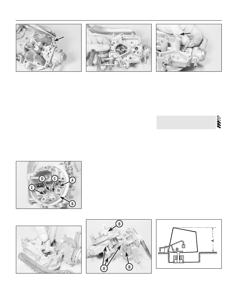
support bracket screw (A), blanking plug
chamber housings
(B), idle mixture screw (C) and idle speed
screw (D)
1932 TL carburettor - overhaul
a lint-free cloth and prepare a clean
and remove the seal ring from the housing
uncluttered working area.
(see illustration).
Note: In the rare event of a complete
3 Disconnect the throttle return spring from
8 As a guide to refitting, count and record the
carburettor overhaul being necessary, it may
the linkage and the support bracket on the
number of turns necessary to screw the
prove more economical to renew the
side of the carburettor (see illustration).
auxiliary idle mixture screw and the basic idle
carburettor as a complete unit. Check the
4 Disconnect the vacuum unit hose from the
mixture screw fully into the housing. Now
4A
price and availability of a replacement
outlet on the throttle valve housing
(see
remove the two screws.
carburettor and of its component parts before
illustration).
9 Undo the four screws and remove the
starting work; note that most sealing washers,
5 Undo the four retaining screws and
accelerator pump cover, diaphragm, and
screws and gaskets are available in kits, as are
separate the carburettor cover from the float
spring from the float chamber housing (see
some of the major sub-assemblies. In most
chamber housing (see illustrations).
illustration).
cases it will be sufficient to dismantle the
6 At the base of the carburettor undo the
10 From the other side of the float chamber
carburettor and to clean the jets and
single securing the throttle valve housing to
housing, undo the three screws and remove
passages.
the float chamber housing (see illustration).
the enrichment valve cover, diaphragm and
1 Remove the carburettor from the engine.
Separate the two housings.
spring (see illustration).
2 Clean the carburettor externally using a
7 Undo the screw securing the choke cable
11 Carefully withdraw the fuel discharge
suitable cleaning solvent, or petrol in a well
support bracket to the throttle valve housing
nozzle from the housing (see illustration).
ventilated area. Wipe the carburettor dry with
and lift off the bracket. Undo the blanking plug
12 Tap the float pivot pin out of the pivot
19.9 Accelerator pump components
19.10 Enrichment valve components
19.11 Removing the fuel discharge nozzle
4A•14 Fuel and exhaust systems - Carburettor models
19.12 Extracting the float pivot pin
19.13 Lift off the gasket
19.14 Removing the float needle valve.
Main jet is arrowed
posts and withdraw the pin using long-nosed
and choke valve rod. Remove the cam and
27 Check the float level as shown after
pliers (see illustration).
spring, disengage the operating rod from the
refitting the float (see illustration). Bend the
13 Lift out the float and then remove the
cam and choke valve lever and withdraw the
float arm if necessary to achieve the specified
gasket from the carburettor top cover (see
assembly (see illustration).
level.
illustration).
19 With the carburettor now dismantled,
28 After refitting the carburettor, carry out the
14 Lift out the float needle valve and then
clean the components in petrol in a well
basic idle adjustment then adjust the idle
unscrew the main jet (see illustration).
ventilated area. Allow the parts to air dry.
speed and mixture settings as described in
15 Unscrew all the jets and plugs from the
20 Blow out all the jets and the passages in
Chapter 1.
carburettor cover, making a careful note of
the housings using compressed air or a tyre
their locations (see illustration). Remove the
foot pump. Never probe with wire.
2035 PDSI carburettor -
mixture tube from the air correction jet bore.
21 Examine the choke and throttle valve
overhaul
16 Withdraw the pre-atomiser from the top
spindles and linkages for wear or excessive
cover venturi (see illustration).
side-play. If wear is apparent in these areas it
Note: In the rare event of a complete
17 Undo the retaining plug and withdraw the
is advisable to obtain an exchange
fuel filter adjacent to the inlet hose connection
carburettor.
carburettor overhaul being necessary, it may
prove more economical to renew the
on the top cover.
22 Check the diaphragms and renew them if
18 If necessary the choke valve operating
they are punctured or show signs of
carburettor as a complete unit. Check the
price and availability of a replacement
linkage and vacuum unit can be removed from
deterioration.
the top cover. Undo the three retaining screws
23. Examine the float for signs of deterioration
carburettor and of its component parts before
starting work; note that most sealing washers,
and the retaining clips for the operating cam
and shake it, listening for fuel inside. If so
renew it, as it is leaking and will give an
screws and gaskets are available in kits, as are
some of the major sub-assemblies.
incorrect float level height causing flooding.
1 Major carburettor overhaul is not a routine
24 Blow through the float needle valve
operation and should only be carried out
assembly while holding the needle valve
when components are obviously worn.
closed, then open. Renew the valve if faulty,
Removing of the cover and mopping out the
or as a matter of course if high mileages have
fuel and any sediment from the fuel bowl, and
been covered.
clearing the jets with compressed air is
25 Obtain the new parts as necessary and
usually sufficient to keep a carburettor in good
also a carburettor repair kit which will contain
working order.
a complete set of gaskets, washers and seals.
2 With the carburettor removed from the
26 Reassemble the carburettor using the
engine and cleaned externally, remove the
reverse of the dismantling procedures, but
clip which retains the fast idle rod to the lever
carry out the settings and adjustments
on the choke valve plate spindle
(see
described in Section
12 as the work
19.15 Plugs (A and B), idle jet (C), air
illustration).
progresses.
correction jet (D) and auxiliary fuel/air jet
(E) in carburettor cover
19.27 Float level measurement
19.16 Removing the pre-atomiser
19.18 Choke linkage screws (A) and
A Measurement point
retaining clips (B)
B Bend here to adjust

Fuel and exhaust systems - Carburettor models 4A•15
20.2 Exploded view of 35 PDSI carburettor
1 Cover
2 Gasket
3 Fuel inlet needle valve
4 Float pivot pin clip
5 Float pivot pin
6 Float
7 Body
8 Fuel cut-off solenoid valve
9 Accelerator pump diaphragm spring
10 Diaphragm
11 Diaphragm housing cover
12 Accelerator pump rod nut
13 Spring
14 Accelerator pump rod
15 Venturi
16 Gasket
17 Idle speed adjustment screw
18 Idle mixture adjustment screw
19 Throttle valve block
20 Fast idle adjustment screw
21 Fast idle link rod
22 Main jet
23 Main jet plug
4A
24 Part load enrichment valve
3 Extract the six screws and remove the
inserted through the hole.
air from a tyre pump; never probe them with
cover.
9 The throttle valve housing is held to the
wire in an attempt to clean them or their
4 Use a socket wrench to unscrew the fuel
main body of the carburettor by two securing
calibration will be ruined.
inlet needle valve.
screws. To remove the housing, first
13 Renew all seals, gaskets, diaphragms etc;
5 Extract the screw plug and withdraw the
disconnect the accelerator pump link and
these will be available in the form of an
metering pin.
then extract the screws.
overhaul kit.
6 Extract the spring clip and withdraw the
10 The accelerator pump housing can be
14 No provision is made for float level
float from the carburettor bowl.
dismantled by extracting the four pump
adjustment, nor is any checking procedure or
7 The part load enrichment valve is screwed
housing screws.
dimension specified.
into the base of the float bowl.
11 Clean all components and examine for
15 Reassemble the carburettor in the reverse
8 The main jet can be unscrewed if the plug in
wear or damage.
order to dismantling, observing the settings
the float bowl is extracted and a screwdriver
12 Blow through all jets and passages with
and adjustments described in Section 13.

4A•16 Fuel and exhaust systems - Carburettor models
21.3 Lifting off the carburettor top cover
21.4 Adjustment screws and idle cut-off
21.5 Throttle valve shaft lever and nut
valve plug (arrowed)
(arrowed)
4 Remove the idle speed and mixture
adjustment screws, and the idle cut-off valve
211B1 carburettor - overhaul
or plug (see illustration).
5 If necessary the throttle valve lever, cam
plate and return spring can be removed after
Note: In the rare event of a complete
removal of the shaft nut (see illustration). As
carburettor overhaul being necessary, it may
they are removed, note their relative positions.
prove more economical to renew the
carburettor as a complete unit. Check the price
6 Remove the two retaining screws and lift off
and availability of a replacement carburettor
the part-load enrichment device cover, spring
and of its component parts before starting
and diaphragm (see illustration).
work; note that most sealing washers, screws
7 Remove the accelerator pump collar, piston
and gaskets are available in kits, as are some of
and spring (see illustrations).
the major sub-assemblies. In most cases it will
8 Pull the accelerator pump delivery tube out
be sufficient to dismantle the carburettor and
of the carburettor body (see illustration).
21.6 Removing the part-load enrichment
to clean the jets and passages.
Note the spring and ball.
device
1 Remove the carburettor from the engine.
9 Press out the float pin and remove the float
2 Detach the vacuum unit pull-down hose
and needle valve (see illustrations).
12 Unscrew and remove the idle fuel/air and
from the throttle body housing.
10 Unscrew and remove the main jet (see
auxiliary fuel/air jets from the carburettor
3 Remove the four retaining screws and
illustration).
body, taking note of the location of each (see
separate the top cover from the carburettor
11 Remove the choke thermal and vacuum
illustration).
body (see illustration).
units by undoing the three retaining screws.
13 Further dismantling is not recommended.
21.7a Removing the accelerator pump
21.7b . . . the piston . . .
21.7c . . . and the spring
collar . . .
21.8 Removing the accelerator pump
21.9a Removing the float . . .
21.9b . . . followed by the needle valve
delivery tube

Fuel and exhaust systems - Carburettor models 4A•17
Clean and inspect the various components as
described in Section 19, paragraphs 19 to 25.
14 Reassembly is a reversal of the
dismantling procedure. Note that float level is
not adjustable on this carburettor.
15 After refitting, adjust the idle speed and
mixture setting as described in Chapter 1 then
carry out the other adjustments described in
Section 14 of this Chapter.
222E3 carburettor - overhaul
21.10 Removing the main jet
21.12 Idle (A) and auxiliary (B) fuel/air jets
Note: Refer to the note at the beginning of
Section 21.
1 With the carburettor removed from the
seat if wear is evident, or if a high mileage has
23 Varajet II carburettor -
vehicle, drain the fuel from the float chamber
been covered. Renew the float if it is
overhaul
and vapour separator. Clean the outside of
punctured or otherwise damaged.
the carburettor.
6 No procedure has been specified for float
Note: Refer to the Note at the beginning of
2 Remove the hoses and wires from the
level adjustment. Simply check that the inlet
Section 21.
carburettor, making identifying marks or notes
needle valve is closed completely before the
to avoid confusion on reassembly
(see
float reaches the top of its stroke.
Automatic choke type
illustrations).
7 Renew the diaphragms in the part load
1 It is rare for the carburettor to require
3 Access to the jets and float chamber is
enrichment valve and in the accelerator pump.
complete dismantling; indeed, normally where
obtained by removing the top half of the
If additional pump or valve parts are supplied
this is required then it would probably be
carburettor, which is secured by five screws.
in the overhaul kit, renew these parts also.
more economical to renew the complete unit.
Blow through the jets and drillings with
8 Further dismantling is not recommended.
2 It will usually be found that the first few
compressed air, or air from a foot pump - do
Pay particular attention to the throttle opening
operations described in the following
not probe them with wire. If it is wished to
mechanism if it is decided to dismantle it: the
paragraphs to remove the cover will be
remove the jets, unscrew them carefully with
interlocking arrangement is important.
sufficient to enable cleaning of the jets and
well-fitting tools.
9 Reassemble in the reverse order to
carburettor float chamber to be carried out.
4 Remove the fuel strainer from the inlet pipe
dismantling. Use new gaskets and seals
3 With the carburettor removed and external
by hooking it out with a small screwdriver, or
throughout; lubricate linkages with a smear of
dirt cleaned away, pull off the vacuum hose
by snaring it with a long thin screw. Renew the
molybdenum based grease.
from the choke vacuum unit (see illustration).
strainer (see illustration).
10 Before refitting the carburettor, carry out
4 Extract the three screws from the automatic
5 Clean any foreign matter from the float
the checks and adjustments described in
choke retaining ring and withdraw the
chamber. Renew the inlet needle valve and
Section 15.
assembly.
4A
22.2a Top view of 2E3 carburettor
1 Vapour separator
2 Choke cover
3 Choke pull-down
unit
4 Fuel hose
5 Thermotime valve
6 Secondary throttle
vacuum unit
22.2b 2E3 carburettor - choke cover side
view
22.2c Side view showing accelerator
22.2d View showing part load enrichment
22.4 Fuel inlet fuel strainer
pump (1) and choke pull-down unit (2)
valve (1) and accelerator pump cam (2)

4A•18 Fuel and exhaust systems - Carburettor models
23.3 Exploded view of Varajet ll
carburettor
1 Cover
2 Gasket
3 Packing piece
4 Float pin
5 Accelerator pump piston
6 Spring
7 Float
8 Fuel inlet needle valve
9 Check ball (accelerator pump)
10 Fuel inlet union
11 Fuel filter
12 Idle speed adjustment screw
13 Link rod
14 Idle mixture adjustment screw
15 Throttle valve block
16 Fast idle screw and spring
17 Gasket
18 Fast idle cam
19 Fast idle link rod
20 Vacuum hose
21 Part load needle valve and piston
22 Spring
23 Suction valve and check ball
24 Choke vacuum unit
25 Choke housing cover
26 Cover retainer
27 Choke valve plate (primary barrel)
28 Baffle flap (secondary barrel)
29 Full load needle valve
5 Extract the split pin and disconnect the
8 Extract the three short and four long
the accelerator pump plunger is under spring
accelerator pump rod from the lever.
carburettor cover retaining screws
(see
tension.
6 Unscrew the fuel inlet nozzle and extract
illustration).
10 Remove the accelerator pump plunger
the gauze filter from inside (see illustration).
9 Remove the cover making sure that, as it is
and spring and carefully peel off the cover
7 Extract the retaining clip and disconnect
withdrawn, the gasket remains behind on the
gasket. Remove the pump suction valve
the choke connecting rod from the cam.
flange of the float chamber. Remember that
spring retainer (see illustration).
23.6 Fuel inlet union and gauze
23.8 Varajet II carburettor top cover
23.10 Accelerator pump plunger and
spring

Fuel and exhaust systems - Carburettor models 4A•19
23.13 Float and needle valve
23.22 Measuring the float level
23.23 Float adjustment points (arrowed)
11 Pull or twist out the vacuum piston spring
automatic choke engages positively with the
10 Disconnect the brake servo vacuum hose.
and needle of the carburettor first stage. Take
choke valve plate spindle arm.
11 Remove the securing nuts and withdraw
care not to bend the retaining bracket or
27 Check the operation of the throttle valve
the manifold. Recover the gasket.
partial load needle.
plate lever. Remember that the secondary
Refitting
12 If necessary, the partial load plunger may
valve plate does not open until the primary
be withdrawn by gripping its rod with a pair of
valve plate has opened by two-thirds of its
12 Refit in the reverse order to removal, using
pliers.
travel. The secondary throttle valve plate will
a new gasket. Tighten the manifold nuts
13 Remove the packing piece, float and
not open until the choke valve plate is fully
progressively to the specified torque. On 1.3,
needle from the float chamber
(see
open after the engine has reached operating
1.4 and 1.6 litre models refill the cooling
illustration). Empty the fuel from the
temperature.
system and adjust the alternator drivebelt, as
chamber.
28 Carry out those checks and adjustments
described in Chapter 1.
14 Note their location and unscrew the jets.
in Section 15 which can be performed with
15 Extract the four retaining screws and
the carburettor on the bench.
25 Exhaust manifold - removal
remove the throttle valve plate block.
29 After refitting, set the idle speed and
and refitting
16 Further dismantling is not recommended.
mixture,
(Chapter
1), then carry out any
17 Clean all components and renew any that
adjustments outstanding from Section 15.
are worn or damaged. If the throttle valve
Removal
Manual choke type
plate spindle is worn then the complete
throttle block must be renewed. Clean jets
30 The operations are very similar to those
1.2 litre models
and passages with air pressure only; never
described in the preceding paragraphs, but
1 Raise and securely support the front of the
probe with wire or their calibration will be
the references to automatic choke
car (see “Jacking and Vehicle Support”).
ruined.
components should be ignored.
2 From under the car, separate the
18 Obtain a repair kit which will contain all
manifold-to-downpipe joint by removing the
the necessary renewable items, including
two bolts and recovering the tension springs.
24 Inlet manifold - removal and
gaskets.
3 Remove the air cleaner, as described in
4A
refitting
19 Reassembly is a reversal of dismantling,
Section 3.
but observe the following points.
4 Remove the six bolts which secure the
20 When assembling the accelerator pump,
Removal
exhaust manifold to the cylinder head.
ensure that the check ball is correctly located.
Remove the manifold and recover the gasket.
21 Check that the needle valve spring is
1.2 litre models
1.3, 1.4 and 1.6 litre models
correctly located on the float arm bracket.
1 The manifold may be removed with or
5 Remove the air cleaner, as described in
There should be approximately 0.2 mm free
without the carburettor. In either case, refer to
Section 3. Also remove the hot air shroud;
play between the spring and the bracket.
Section 18 and follow the steps preparing for
noting how its sections fit over the manifold.
Correct if necessary by carefully bending one
carburettor removal.
item or the other.
2 Disconnect the brake servo vacuum hose.
22 Refit the float, needle valve and pivot
3 Remove the three screws which secure the
clips. Check the float level, with the gasket
manifold to the cylinder head
(see
fitted, by applying moderate finger pressure to
illustration).
the float arms and pivot clip to close the
4 Remove the manifold and recover the
needle valve
(see illustration). The top
gasket.
surface of the float should be the specified
1.3, 1.4 and 1.6 litre models
distance below the carburettor top flange.
23 Correct the float level if necessary by
5 Drain the cooling system, as described in
Chapter 1.
carefully bending the float arms at the points
6 Remove the alternator, as described in
shown (see illustration).
Chapter 5.
24 When installing the cover to the
carburettor body, take care that the
7 Release the coolant pipe from the inlet
manifold and clutch housing.
accelerator pump plunger does not become
8 On 1.3 models, disconnect the coolant
wedged.
temperature gauge lead.
25 Make sure that the breather screen is in
9 Refer to Section 18 and either remove the
position.
carburettor, or follow the steps preparing for
24.3 Three screws (arrowed) securing inlet
26 Check that the bi-metallic spring of the
carburettor removal.
manifold - 1.2 litre models

4A•20 Fuel and exhaust systems - Carburettor models
27.4a Exhaust system flexible joint
27.4b Exhaust system rubber mounting
27.5 Graphite sealing ring fitted at the
ring
flexible joint
6 Remove the securing nuts or bolts from the
Removal
Removal
manifold-to-downpipe joint.
2 Disconnect the battery earth
(negative)
2 To remove the exhaust system, jack up the
7 Remove the manifold securing nuts and
lead.
front and/or rear of the car and support it
withdraw the manifold from the studs.
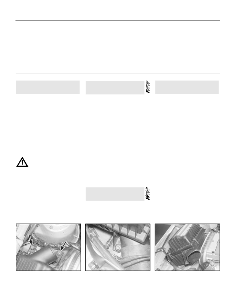
3 Disconnect the pre-heater wiring
securely on axle stands (see “Jacking and
Recover the gaskets.
multi-plug.
Vehicle Support”). Alternatively drive the front
Refitting
4 Remove the screws which secure the
or rear wheels up on ramps or over a pit.
pre-heater to the inlet manifold. Pull the
3 The system is made up of three or four
1.2 litre models
pre-heater downwards and remove it.
sections. The front and rear sections can be
8 Refit in the reverse order to removal, using
removed independently, but to remove a
Refitting
a new gasket. Tighten the manifold securing
middle section it will be necessary to remove
bolts progressively, starting in the middle and
5 Refitting is the reverse of the removal
an adjacent end section also. it is certainly
working towards the ends, to avoid
procedure. Make sure that the pre-heater and
easier to free stubborn joints with the
destructive stresses. Use a little anti-seize
manifold are clean, and use a new sealing
complete system removed from the car.
compound on the downpipe joint, and a new
ring.
4 To remove a front or rear section, remove
seal if necessary.
the U-bolt clamps which hold the section
together. Unhook the section from its rubber
1.3, 1.4 and litre models
27 Exhaust system - inspection,
mounting rings, and for the front section
9 Refit in the reverse order to removal. Use a
removal and refitting
unbolt the manifold or downpipe
(see
new gasket and tighten the nuts as described
illustrations). Free the joints and remove the
in paragraph 5. Also renew the gasket or seal
Inspection
section concerned. The application of
at the downpipe joint.
penetrating oil will be of assistance in freeing
1 The exhaust system should be examined
seized joints. Heat from a blowlamp can also
for leaks, damage and security at the intervals
26 Inlet manifold pre-heater (1.6
be helpful, but take great care to shield the
given in Routine Maintenance. To do this,
litre models with automatic
fuel tank, fuel lines and other vulnerable or
apply the handbrake and allow the engine to
transmission) - general
inflammable areas.
idle. Lie down on each side of the car in turn,
information, removal and refitting
and check the full length of the exhaust
Refitting
system for leaks while an assistant
5 Use a little exhaust jointing compound
temporarily places a wad of cloth over the end
when assembling joints. Renew clamps,
General information
of the tailpipe. If a leak is evident repairs may
rubber rings, seals and gaskets as a matter of
1 An electric manifold pre-heater is fitted to
be made using a proprietary exhaust repair
course unless they are in perfect condition
some 1.6 litre models (fitted with a 16SH
kit. If the leak is excessive, or damage is
(see illustration).
engine) with automatic transmission. If it
evident, the relevant section should be
6 When refitting the complete exhaust
malfunctions, warm-up time will be prolonged
renewed. Check the rubber mountings for
system, position it so that the mountings are
and cold driveability will suffer.
condition and security and renew them if
evenly loaded before tightening the U-bolt
necessary.
clamps.

4B•1
Chapter 4 Part B:
Fuel and exhaust systems - fuel-injected models
Contents
Accelerator cable - removal, refitting and adjustment
3
Fuel system - depressurisation
6
Air cleaner filter element renewal
See Chapter 1
Fuel tank - removal and refitting
9
Air cleaner housing - removal and refitting
2
General fuel system checks
See Chapter 1
Exhaust manifold - removal and refitting
14
General information and precautions
1
Exhaust system - removal and refitting
15
Idle speed and mixture adjustment information
See Chapter 1
Exhaust system check
See Chapter 1
Inlet manifold - removal and refitting
13
Fuel filter renewal
See Chapter 1
Multi-point fuel injection system components (1.8 and 2.0 litre
Fuel gauge sender unit - removal and refitting
8
models) - removal and refitting
12
Fuel injection system - general information
5
Single point fuel injection system components (1.4 and 1.6 litre
Fuel injection system - testing and adjustment
10
models) - removal and refitting
11
Fuel pump - removal and refitting
7
Unleaded petrol - general information and usage
4
Degrees of difficulty
Easy, suitable for
Fairly easy, suitable
Fairly difficult,
Difficult, suitable for
Very difficult,
novice with little
for beginner with
suitable for competent
experienced DIY
suitable for expert
experience
some experience
DIY mechanic
mechanic
DIY or professional
Specifications
System type
1.4 and 1.6 litre models
Multec CFI (single-point injection)
1.8 litre models:
Early (18E engine) models
Bosch LE Jetronic (multi-point injection)
Later (18SE engine) models
Bosch L3 Jetronic (multi-point injection)
2.0 litre models:
8-valve models:
4B
Early (Pre 1990) models
Bosch Motronic ML4.1 (multi-point injection)
Later (1990 on) models
Bosch Motronic M1.5 (multi-point injection)
16-valve models
Bosch Motronic M2.5 (multi-point injection)
Fuel pump
Type
Electric
Pressure:
1.4 and 1.6 litre models
1.0 bar
1.8 and 2.0 litre models
2.5 bar
Adjustment data
Idle speed:
1.4 litre models
830 to 990 rpm
1.6 litre models
720 to 880 rpm
1.8 litre models:
Early (pre 1990) models:
Manual transmission
900 to 950 rpm
Automatic transmission
800 to 850 rpm
Later (1990 on) models
800 to 900 rpm
2.0 litre models
720 to 780 rpm (not adjustable - regulated by control unit)
Exhaust gas CO content (at idle)
Less than 1.0%*
*On models equipped with a catalytic converter the exhaust gas CO content is regulated by the control unit and is not adjustable
Recommended fuel
Minimum octane rating:
Models without a catalytic converter
98 RON leaded (4-star) or unleaded (Super unleaded)*
Models with a catalytic converter
95 RON unleaded (Unleaded premium) only
*If the necessary precautions are taken, 95 RON unleaded (unleaded premium) petrol can be used (see Section 4 for details)
4B•2 Fuel and exhaust systems - fuel-injected models
Torque wrench setting
Nm
lbf ft
Multec CFI components:
Throttle body/injector unit retaining nuts
22
16
Throttle body/injector housing upper section retaining screws
6
4
Inlet manifold
22
16
Throttle valve potentiometer screws
2
2
Injector valve bolt
3
2
Pressure regulator unit screws
3
2
Idle air control stepper motor retaining screws
3
2
Oxygen sensor unit
38
28
Inlet manifold nuts and bolts
22
16
1 General information and
2 Air cleaner housing - removal
4 Unleaded petrol - general
precautions
and refitting
information and usage
1 The fuel system consists of a fuel tank
Note: The information given in this Chapter is
Removal
mounted under the rear of the car with an
correct at the time of writing and applies only
electric fuel pump immersed in it, a fuel filter,
to petrols currently available in the UK. If
1.4 and 1.6 litre models
fuel feed and return lines. On 1.4 and 1.6 litre
updated information is thought to be required
1 Refer to the information given for the
models, the pump supplies fuel to throttle body
check with a Vauxhall dealer. If travelling
carburettor models in Chapter
4A. For
unit which incorporates the fuel injection valve
abroad consult one of the motoring
information on the air temperature control
and pressure regulator. On 1.8 and 2.0 litre
organisations (or a similar authority) for advice
system refer to Chapter 4A, Section 4.
models, the fuel pump supplies fuel to the fuel
on the petrols available and their suitability for
rail which acts as a reservoir for the four fuel
1.8 and 2.0 litre 8-valve models
your vehicle.
injectors which inject fuel into the inlet tracts.
2 Remove the air cleaner element as
1 The fuel recommended by Vauxhall is given
On all models a fuel filter is incorporated in the
described in Chapter 1.
in the Specifications Section of this Chapter,
feed line from the pump to the fuel rail to ensure
3 Disconnect the air intake tube then undo
followed by the equivalent petrol currently on
the fuel supplied to the injectors is clean.
the retaining screws and remove the housing
sale in the UK.
2 Refer to Section 5 for further information on
from the engine compartment.
2 RON and MON are different testing
the operation of the relevant fuel injection
standards; RON stands for Research Octane
2.0 litre 16-valve models
system.
Number (also written as RM), while MON
Warning: Many of the
4 Remove the trunking which connects the air
stands for Motor Octane Number. Fuel
procedures in this Chapter
cleaner to the air mass meter.
requirements are as follows.
require the removal of fuel lines
5 Remove the three bolts which secure the air
cleaner. Remove the air cleaner
(see
1.4 and 1.6 litre models
and connections which may
result in some fuel spillage. Before
illustrations).
3 All 1.4 and 1.6 litre fuel-injected models are
carrying out any operation on the fuel
fitted with catalytic converters and must
Refitting
system refer to the precautions given in
therefore be run on 95 (RON) unleaded fuel
Safety first! at the beginning of this
6 Refit by reversing the removal operations.
only. Under no circumstances should leaded
Manual and follow them implicitly. Petrol
(UK “4-star”) fuel be used as this will damage
is a highly dangerous and volatile liquid
3 Accelerator cable - removal,
the catalytic converter.
and the precautions necessary when
refitting and adjustment
1.8 litre models
handling it cannot be overstressed.
4 All 1.8 litre models are designed to run on
Refer to Chapter 4A, Section 9, substituting
Note: Residual pressure will remain in the fuel
98 (RON) octane leaded or unleaded petrol
“throttle housing” in for all references to the
lines long after the vehicle was last used, when
(see Specifications). If it is wished to run the
“carburettor”.
disconnecting any fuel line, depressurise the
vehicle on
95 (RON) unleaded petrol the
fuel system as described in Section 7.
following operations must first be carried out;
2.5a Two of the air cleaner securing bolts
2.5b The third air cleaner bolt - 2.0 litre
2.5c Removing the air cleaner - 2.0 litre
(arrowed) - 2.0 litre 16-valve
16-valve
16-valve

Fuel and exhaust systems - fuel-injected models 4B•3
this is necessary to avoid detenation
control unit, and from these signals, the
(knocking and pinking) which could lead to
appropriate control impulses for the fuel
possible engine damage
injectors are generated Additional
5 On early (18E engine) models, to allow the
circuitry within the control unit operates
vehicle to run on 95 (RON) unleaded petrol,
an overrun fuel cut-off to reduce fuel
the ignition timing must be retarded by 3
consumption, and a cold start booster for
(see Chapter 5 for details). Do not use 95
cold starting fuel enrichment.
(RON) unleaded petrol if the ignition timing
b) Control relay - this comprises an
has not been retarded.
electronic timing element and a switch
6 On later (18SE engine) models a fuel octane
relay, which cuts off the fuel supply
rating coding plug in the ignition system wiring
immediately after the engine stops.
harness (see illustration). The plug which is
c)
Airflow sensor - the amount of air drawn
located on the right-hand side of the engine
in by the engine is measured by the
compartment, is set during production to give
4.6 Octane rating plug in the “95” setting
airflow sensor to determine the engine
optimum engine output and efficiency when
position
load condition. This is achieved by using a
run on 98 (RON) fuel. To run the vehicle on 95
flap valve attached to a spindle, which is
crankshaft position from the distributor; road
(RON) unleaded fuel, the plug position can be
free to pivot within the airflow sensor
speed from a sensor at the base of the
reset to modify the timing characteristics of the
bore, and is deflected by the passage of
speedometer cable; the position of the throttle
ignition system. To reset the plug, release its
intake air. Attached to the flap valve
valve plate from the throttle position sensor;
locking clip then remove the plug and rotate it
spindle is a potentiometer, which
engine coolant temperature; and the oxygen
through half a turn (180º) before reconnecting
transforms the angular position of the flap
content in the exhaust gases via a sensor in
it. Note: If after making the adjustment, the
valve into a voltage, which is then sent to
the exhaust manifold. Battery voltage is also
the control unit. Airflow passing through
octane rating of the fuel used is found to be so
monitored by the ECU.
low that excessive knocking still occurs, seek
the sensor is one of the main variables
3 Using the information gathered from the
the advice of your Vauxhall dealer.
used by the control unit to determine the
various sensors, the ECU sends out signals to
precise fuel requirement for the engine at
2.0 litre models
control the system actuators. The actuators
any given time.
include the fuel injector, the idle air control
7 On all models with a catalytic converter, 95
d) Fuel injectors - each fuel injector consists
stepper motor, the fuel pump relay and the
(RON) unleaded fuel must be used. Under no
of a solenoid-operated needle valve,
ignition control unit.
circumstances should leaded (UK “4-star”)
which opens under commands from the
4 The ECU also has a diagnostic function
fuel be used as this will damage the catalytic
control unit. Fuel from the fuel distribution
which can be used in conjunction with special
converter.
pipe is then delivered through the injector
Vauxhall test equipment for fault diagnosis.
8 All models not equipped with a catalytic
nozzle into the inlet manifold. All four fuel
With the exception of basic checks to ensure
injectors operate simultaneously; once for
converter can be are designed to run on 98
that all relevant wiring and hoses are in good
(RON) octane leaded or unleaded petrol (see
each turn of the crankshaft regardless of
condition and securely connected, fault
inlet valve position. Therefore, each
Specifications). If it is wished to run the
diagnosis should be entrusted to a Vauxhall
injector will operate once with the inlet
vehicle on 95 (RON) unleaded petrol, the fuel
dealer.
octane rating plug must be set to the “95”
valve closed, and once with it open, for
5 The system incorporates a three-way
each cycle of the engine. The fuel
position (see paragraph 6); this is necessary
catalytic converter to reduce exhaust gas
to avoid detenation (knocking and pinking)
injectors always open at the same time
pollutants, and a closed-loop fuel mixture
4B
relative to crankshaft position, but the
which could lead to possible engine damage
control (by means of the exhaust gas oxygen
length of time in which they stay open, eg
sensor) is used. The mixture control remains
the injector duration, is governed by other
5 Fuel injection system - general
in
an
open-loop
mode
(using
variables, and is determined by the
pre-programmed values stored in the ECU
information
control unit. For a given volume of air
memory) until the exhaust gas oxygen sensor
passing through the airflow sensor, the
reaches its normal operating temperature.
control unit can enrich the air/fuel mixture
1.4 and 1.6 litre models
1.8 litre models
ratio by increasing the injector duration,
1 The MULTEC Central Fuel injection (CFI)
or weaken it by decreasing the duration.
system is fitted to 1.4 litre (C14NZ) and 1.6
Early (18E engine) models
e)
Fuel pump - the fuel pump is an electric
litre (C16NZ) engine models and provides a
6 A Bosch LE Jetronic fuel injection system is
self-priming roller cell unit, located at the
simple method of fuel metering whereby fuel
fitted to all early 1.8 litre models fitted with the
rear of the car. Fuel from the tank is
is injected into the inlet manifold by a single
18E engine.
delivered by the pump, at a
solenoid operated fuel injector unit. The
7 By means of electronic control, the fuel
predetermined pressure, through the fuel
injector unit is located centrally in the top of
injection system supplies the precise amount
filter to the fuel distribution pipe. From the
the throttle valve housing and this is mounted
of fuel for optimum engine performance with
fuel distribution pipe, the fuel is supplied
on the top of the inlet manifold. The length of
minimum exhaust emission levels. This is
to the four fuel injectors the excess being
time for which the injector remains open
achieved by continuously monitoring the
returned to the fuel tank via the fuel
determines the quantity of fuel reaching the
engine using various sensors, whose data is
pressure regulator. A greater volume of
cylinders for combustion. The electrical
input to an electronic control unit in the form
fuel is circulated through the system than
signals which determine the fuel injector
of electrical signals. Based on this constantly-
will be needed, even under the most
opening duration are calculated by the
changing data, the control unit determines the
extreme operating conditions, and this
Electronic Control Unit
(ECU) from the
fuel necessary to suit all engine speed and
continual flow ensures that a low fuel
information supplied by a network of sensors.
load conditions, which is then injected directly
temperature is maintained. This reduces
The fuel pressure is regulated mechanically.
into the inlet manifold.
the possibility of vapour lock, and ensures
2 The signals fed to the ECU include inlet
8 The main components of the system are:
good hot starting characteristics.
manifold vacuum from the Manifold Absolute
a) Control unit - the signals delivered by the
f)
Fuel pressure regulator - the fuel pressure
Pressure (MAP) sensor; engine speed and
various sensors are processed in the
regulator Is fitted to the fuel distribution
4B•4 Fuel and exhaust systems - fuel-injected models
pipe, and controls the operating pressure
Later (1987 onwards) 1.8 litre models
dealers or other specialists with the necessary
in the fuel system. The unit consists of a
test equipment.
9 A Bosch L3 Jetronic fuel injection system is
metal housing, divided into two chambers
19 If a fault is detected by the control unit, a
fitted to all later 1.8 litre models fitted with the
by a diaphragm. Fuel from the fuel
‘limp home’ program comes into operation by
18SE engine.
distribution pipe fills one chamber of the
means of which an average value is
10 The system is based on the LE system
regulator, whilst the other chamber
substituted for the normal output of a
used previously, but it has a digital control
defective or disconnected sensor. In this case
contains a compression spring, and is
system, rather than the analogue system used
the vehicle is still driveable, albeit with reduced
subject to inlet manifold vacuum via a
on the LE type. The L3 system control unit is
performance and efficiency. A warning light on
hose connected to the manifold,
housed within the engine compartment as
the instrument panel, carrying an outline of an
downstream of the throttle valve. A valve
part of the airflow sensor assembly, and the
engine and a lightning symbol, warns the
attached to the diaphragm opens a fuel
system wiring layout differs to suit.
driver that a fault has occurred.
return port in the fuel chamber of the
2.0 litre models
regulator as the diaphragm deflects.
11 The Motronic systems fitted to 2.0 litre
When the fuel pressure in the regulator
models control the fuel injection and ignition
6 Fuel system - depressurisation
exceeds a certain value, the diaphragm is
systems as an integrated package. This has
deflected, and fuel returns to the tank
considerable advantages in terms of
through the now open return port. This
Note: Refer to the warning note in Section 1
efficiency, performance and reduction of
also occurs when the port is opened by
before proceeding.
exhaust emissions.
the deflection of the diaphragm under the
12 Idle speed is regulated by the opening
Warning: The following
influence of manifold vacuum. Therefore,
procedure will merely relieve
and closing of an electrically-operated valve
as manifold vacuum increases, the
which allows air to bypass the throttle
the pressure in the fuel system -
regulated fuel pressure is reduced in
butterfly. No manual adjustment is possible.
remember that fuel will still be
direct proportion.
13 Ignition timing is advanced and retarded
present in the system components and
g) Throttle valve switch - the throttle valve
electronically in response to engine speed and
take precautions accordingly before
switch is attached to the throttle spindle
load, engine temperature and inducted air
disconnecting any of them.
on the throttle valve housing. As the
temperature. Engine speed information comes
throttle spindle turns in response to
from an inductive pulse sensor on the side of
1 The fuel system referred to in this Section is
movement of the accelerator pedal,
the cylinder block. The sensor is mounted
defined as the tank-mounted fuel pump, the
contacts within the switch are closed at
close to the toothed lockwasher attached to
fuel filter, the fuel injectors, the fuel rail and
the two extremes of shaft movement. One
the crankshaft No
1 counterweight. The
the pressure regulator, and the metal pipes
contact closes in the idle position, and
passage of each lockwasher tooth produces
and flexible hoses of the fuel lines between
one in the full-throttle position. These
an electrical pulse in the sensor. This signal is
these components. All these contain fuel
signals are then processed by the control
transmitted to the control unit.
which will be under pressure while the engine
unit to determine throttle valve position.
14 The system fitted to
8-valve models
is running and/or while the ignition is switched
before 1990 is known as Motronic ML4.1. The
h)
Auxiliary air valve - this device comprises
on. The pressure will remain for some time
fuel injection side is very similar to the LE/L3
a large-bore air channel, connected by
after the ignition has been switched off and
Jetronic systems fitted to 1.8 models. The
hoses to the throttle housing and inlet
must be relieved before any of these
control unit is located behind the trim panel in
manifold, and allowing intake air to
components are disturbed for servicing work.
the driver’s footwell.
bypass the throttle valve. In the centre of
2 Disconnect the battery negative terminal.
15 1990 8-valve models are fitted with a
the air channel is a blocking plate
3 Place a container beneath the relevant
system known as Motronic M1.5. The main
attached to a bi-metal strip. When the
connection/union to be disconnected, and
difference is in the control unit, which triggers
engine is cold, the blocking plate is
have a large rag ready to soak up any fuel not
the injectors in pairs instead of all together as
withdrawn from the air channel, allowing
being caught by the container.
previously. There are also minor differences in
air to pass through the valve. As the
4 Slowly loosen the connection or union nut
the fixings of the fuel pressure regulator and
engine warms up, a current is supplied to
the fuel injector rail. The fuel pump is now
(as applicable) to avoid a sudden release of
the valve, heating the bi-metal strip and
immersed in the tank instead of being fitted
pressure and position the rag around the
causing the blocking plate to begin
alongside.
connection to catch any fuel spray which may
closing the air channel until, as engine
16 The system fitted to 16-valve models is
be expelled. Once the pressure is released,
temperature increases, the channel is
known as Motronic M2.5. The most significant
disconnect the fuel line and insert plugs to
closed completely. The additional air
difference from the other Motronic systems is
minimise fuel loss and prevent the entry of dirt
passing through the valve is measured by
in the way that intake air is measured. Where
into the fuel system.
the airflow sensor, which compensates by
the other systems measure air volume by
means of a flap, the M2.5 system measures
increasing the injector duration to provide
7 Fuel pump - removal and
additional fuel. Therefore, the engine
air mass by its cooling effect on a hot wire.
refitting
The M2.5 system also incorporates knock
receives a greater air/fuel mixture during
control, whereby detonation (pre-ignition or
cold driveaway and warm-up conditions.
pinking) is sensed and causes the ignition
Note: Refer to the warning note in Section 1
i)
Temperature sensors - information on
timing to be retarded.
before proceeding.
engine (coolant) temperature and intake
17 Injection on the M2.5 system is fully
air temperatures are measured by
Removal
sequential. Each injector is individually
sensors, one located in the coolant jacket
controlled to deliver fuel at the optimum
1.4, 1.6 and later (1990 on) 2.0 litre 8-
and the other in the intake air stream. The
moment in the induction process. The ignition
valve models
sensors consist of resistors whose
distributor carries a Hall Effect sensor which
resistance decreases as temperature
sends the control unit a cylinder recognition
1 The fuel pump is located inside the fuel
increases. The change in electrical
signal.
tank. Before removing the pump, detach the
resistance of the sensors is measured by
18 On all systems, the control unit
battery earth lead.
the control unit, and this information is
incorporates self-testing and fault detection
2 Lift up the rear seat cushion and remove
used to modify injector duration
features. Fault codes are stored in the unit,
the access cover from the floor to reveal the
accordingly.
but these are only accessible to Vauxhall
pump.

Fuel and exhaust systems - fuel-injected models 4B•5
11 Single-point fuel injection
9 Fuel tank - removal and refitting
system components (1.4 and
1.6 litre models) - removal and
Refer to Chapter 4 Part A, Section 7.
refitting
10 Fuel injection system - testing
1 Disconnect the battery negative lead and
proceed as described under the relevant sub-
and adjustment
heading (see illustration).
Throttle body/injector housing
Testing
unit components
1 If a fault appears in the fuel injection system
2 The following items can be removed from
7.6 Fuel pump, damper and filter assembly
first ensure that all the system wiring
the throttle body/injector housing unit for
connectors are securely connected and free
inspection and where necessary, renewal. If
3 Disconnect the electrical connectors from
of corrosion. Then ensure that the fault is not
the unit is in position in the car, first remove
the pump.
due to poor maintenance; ie, check that the
the air cleaner unit to allow suitable access to
4 Bearing in mind the information in Section 6,
air cleaner filter element is clean, the spark
the appropriate component (see illustration).
slacken the retaining clip and disconnect the
plugs are in good condition and correctly
Throttle valve potentiometer
fuel hose. Plug the hose end to minimise fuel
gapped, the cylinder compression pressures
loss.
3 Disconnect the wiring connector from the
are correct, the ignition timing is correct and
5 Undo the retaining bolts and remove the
potentiometer, then undo the retaining screws
the engine breather hoses are clear and
pump assembly from the tank. Recover the
and remove the potentiometer from the
undamaged, referring to Chapters 1, 2 and 5
throttle housing (see illustrations).
rubber seal.
for further information.
4 Refitting is a reversal of the removal
1.8 and 2.0 litre models (except later
2 If these checks fail to reveal the cause of
procedure. Ensure that the throttle valve is fully
1990 on 2.0 litre 8-valve models)
the problem the vehicle should be taken to a
shut as the potentiometer is fitted into position
6 The fuel pump is located underneath the
suitably equipped Vauxhall dealer for testing.
and that the pick-up is properly seated on the
vehicle, just in front of the fuel tank
(see
Your dealer has access to special electronic
throttle spindle. Tighten the retaining screws to
illustration). Before removing the pump or
the specified torque setting.
diagnostic equipment which will locate the
associated components, detach the battery
5 Reconnect the wiring plug and refit the air
fault quickly and simply, alleviating the need
earth lead.
cleaner unit.
to test all the system components individually
7 Clamp the fuel hoses on either side of the
(a time consuming operation that carries a
Injection valve
pump to prevent loss of fuel when they are
disconnected. Self-locking grips are useful for
high risk of damaging the control unit).
6 Disconnect the wiring plug. Undo the
this. Disconnect the hoses, bearing in mind
retaining screw then carefully lever the
Adjustment
the information given in Section 6.
injection valve free using a suitable
8 Unscrew the pump mounting clamp bolts
3 On
1.4 and
1.6 litre models, whilst
screwdriver. Remove the injection valve
and withdraw the pump from its flexible
experienced home mechanics with a
together with its holder (see illustrations).
insulator. Disconnect the electrical plug as the
considerable amount of skill and equipment
7 Refit in the reverse order of removal.
Always renew the seal rings and as the
4B
pump is withdrawn.
(including a good-quality tachometer and a
9 Alternatively, the pump can be removed
good-quality, carefully-calibrated exhaust gas
injection unit is pressed into position, ensure
complete with filter and damper diaphragm
that the wiring connector is facing up (towards
analyser) may be able to check the exhaust
unit if the mounting strap nuts are unscrewed
the retaining screw). If the retaining screw was
CO level and the idle speed, if these are found
and the assembly removed from its flexible
fitted with a washer, discard the washer and
to be in need of adjustment the car must be
mountings.
apply a suitable locking compound to the
taken to a suitably-equipped Vauxhall dealer
screw threads before screwing it into position.
Refitting
for testing. Neither the mixture (exhaust gas
Throttle body upper injector housing
CO level) or idle speed are adjustable, and
1.4, 1.6 and later (1990 on) 2.0 litre 8-
8 Detach the wiring connector, undo the
should either be incorrect then a fault must be
valve models
retaining screws and lift the upper injector
present in the fuel injection system.
10 Refitting is the reversal of removal using a
housing clear of the main body. Remove the
4 On 1.8 litre models, both the idle speed and
new rubber seal. Prior to refitting make sure
seal.
idle mixture
(exhaust gas CO level) are
the pump filter is clean and undamaged. If
9 Unscrew the union nuts and detach the fuel
adjustable. Refer to Chapter 1 for information
necessary, unclip the filter and renew it.
lines from the injector housing.
on the adjustment procedure.
10 Refit in the reverse order of removal.
1.8 and 2.0 litre models (except later
5 On 2.0 litre models not equipped with a
Remove the seal located between the upper
1990 on 2.0 litre 8-valve models)
catalytic converter the idle mixture (exhaust
housing and the main body. Where the retaining
11 Refitting is the reverse of removal,
gas CO level) can be adjusted as described in
screws were fitted with washers, discard the
ensuring the hose clips are securely
Chapter
1, however the idle speed is
washers and coat the threads of the screws
tightened. On completion, start the engine
regulated by the control unit and is not
with a suitable locking compound. Tighten the
and check the hoses for signs of leakage.
adjustable. On models with a catalytic
retaining screws to the specified torque to
converter, both the idle speed and mixture
secure the upper body to the main body.
8 Fuel gauge sender unit -
(exhaust gas CO level) are regulated by the
Idle air stepper motor
removal and refitting
control unit (see paragraph 3). Should the idle
11 Detach the wiring connector, undo the
speed/mixture (as applicable) be incorrect
retaining screws and withdraw the idle air
Refer to Chapter 4 Part A, Section 6.
then a fault must be present in the fuel
stepper motor unit from the injector unit
injection system.
housing (see illustrations).

4B•6 Fuel and exhaust systems - fuel-injected models
11.1 Single-point fuel injection system components and location on 1.4 litre model
1 Throttle valve injection
housing
2 Fuel pump sensor
3 Filter
4 Fuel pressure regulator
5 Injection valve
6 Throttle valve
(potentiometer)
7 Idle air stepper motor
8 Inlet manifold pressure
sensor
9 Coolant temperature sensor
10 Road speed sensor
11 Octane number plug
(95/91)
12 Unheated oxygen sensor
13 Ignition distributor (Hall)
14 Engine telltale
15 ALDL plug
16 Wiring harness
17 Control unit
18 Three-way catalytic
converter
19 Exhaust system
20 Heat shield
21 Tank filler neck
22 Damping control system
11.2 Exploded view of the throttle body/injector
housing assembly - 1.4 and 1.6 litre models
1 Air filter seal
2 Injection valve
3 Injection valve holder
4 Upper O-ring
5 Lower O-ring
6 Upper housing
7 Seal
8 Fuel inlet connector
9 Fuel inlet seal
10 Fuel return connector
11 Fuel pressure regulator diaphragm
12 Fuel pressure regulator spring
13 Fuel pressure regulator spring seat
14 Fuel pressure regulator cover
15 Connecting cable grommet
16 Throttle body
17 Potentiometer (throttle valve)
18 Idle air stepper motor
19 O-ring
20 Idle adjustment screw
21 Idle adjustment screw spring
22 Cap
23 Vacuum connections flange
24 Vacuum connections flange seal
25 Injector housing- inlet manifold seal