Nissan Rogue Hybrid (2019 year). Manual - part 14


  Index      Nissan     Nissan Rogue Hybrid - service manual 2019 year in english


Search            copyright infringement  


Content   ..  12  13  14  15   ..


Nissan Rogue Hybrid (2019 year). Manual - part 14


OUTSIDE MIRRORS

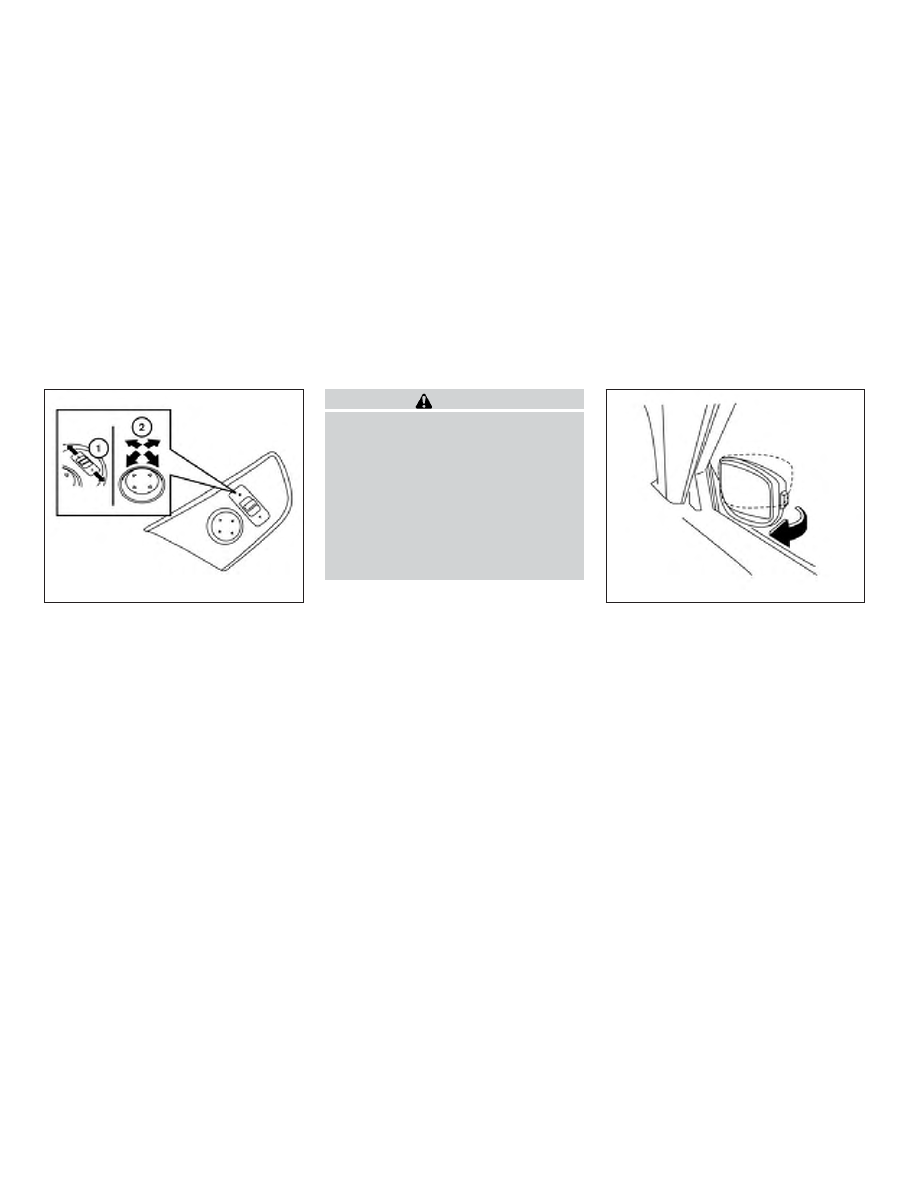
The outside mirror remote control will op-
erate only when the ignition switch is in the
ON position.

Move the small switch

1

to select the left

or right mirror. Adjust each mirror to the
desired position using the large switch

2

.

Move the switch

1

to the center (neutral)

position to prevent accidentally moving
the mirror.

WARNING

∙ Objects viewed in the outside mirror

on the passenger side are closer than
they appear. Be careful when moving
to the right. Using only this mirror
could cause an accident. Use the in-
side mirror or glance over your shoul-
der to properly judge distances to
other objects.

∙ Do not adjust the mirrors while driv-

ing. You could lose control of your ve-
hicle and cause an accident.

Manual folding outside mirrors

Pull the outside mirror toward the door to
fold it.

Reverse tilt-down feature (if so
equipped)

The reverse tilt-down feature will turn both
outside mirror surfaces downward to pro-
vide better rear visibility close to the vehicle
when the mirror control switch is in either
the L or R position.

The mirrors automatically return to their
original position when you shift out of R
(Reverse).

LPD2452

LPD2084

3-38

Pre-driving checks and adjustments

The outside mirror surfaces will return to
their original position when one of the fol-
lowing conditions has occurred:

∙ The shift lever is moved to any position

other than R (Reverse).

∙ The outside mirror control switch is set

to the neutral or center position.

∙ The ignition switch is placed in the OFF

position.

NOTE:

If the outside mirror control switch is in
the “center” position, the mirror surface
will NOT turn downward when the shift
lever is moved to R (Reverse).

For additional information, refer to “Auto-
matic drive positioner” in this section.

Heated mirrors (if so equipped)

Some outside mirrors can be heated to
defrost, defog, or de-ice for improved vis-
ibility. For additional information, refer to
“Rear window and outside mirror (if so
equipped) defroster switch” in the “Instru-
ments and controls” section of this manual.

The automatic drive positioner system has
two features:

∙ Memory storage function

∙ Entry/exit function

MEMORY STORAGE FUNCTION

Two positions for the driver’s seat and out-
side mirrors can be stored in the automatic
drive positioner memory. Follow these pro-
cedures to use the memory system.

1. Place the ignition in the ON or OFF po-

sition (the vehicle should be stopped
while setting the memory).

2. Adjust the driver’s seat and outside

mirrors to the desired positions by
manually operating each adjusting
switch. For additional information, refer
to “Seats” in the “Safety—Seats, seat
belts and supplemental restraint sys-
tem” section of this manual and “Out-
side mirrors” in this section.

LPD2531

AUTOMATIC DRIVE POSITIONER (if so
equipped)

Pre-driving checks and adjustments

3-39

3. Push the SET switch and, within 5 sec-

onds, push the memory switch (1 or 2).

4. The indicator light for the pushed

memory switch will come on and stay
on for approximately 5 seconds.

5. The chime will sound if the memory

has been stored.

NOTE:

If a new memory position is stored in the
same memory switch, the previous
memory position will be overwritten by
the new stored position.

Confirming memory storage

∙ Push the SET switch.

∙ If a memory position has not been

stored in the switch (1 or 2) the indicator
light for the respective switch will come
ON for approximately 0.5 seconds.

∙ If a memory position has been stored in

the switch (1 or 2) then the indicator light
for the respective switch will stay ON for
approximately 5 seconds.

Linking a key fob to a stored
memory position

Each key fob can be linked to a stored
memory position (memory switch 1 or 2)
with the following procedure.

1. Follow steps 1-3 in the “Memory storage

function”

section

for

storing

the

memory position.

2. The indicator light for the pushed

memory switch will come on. While the
indicator light is on for 5 seconds, press
the

button on the key fob. The

indicator light of the linked memory
switch will blink. After the indicator light
goes off, the key fob is linked to that
memory setting.

Once it is linked, when ignition switch is
placed

in

the

OFF

position, pressing

the

button on the key fob will move

the driver’s seat and outside mirrors to the
linked memory switch position.

NOTE:

If a new memory position is stored in the
linked memory switch, then the key fob
will link the new position and overwrites
the previous position.

ENTRY/EXIT FUNCTION

This system is designed so that the driver’s
seat will automatically move when the shift
lever is in the P (Park) position. This allows
the driver to get into and out of the driver’s
seat more easily.

The driver’s seat will slide backward:

∙ When the driver’s door is opened with

the ignition switch placed in the OFF
position.

∙ When the ignition switch is changed

from ON to OFF with the driver’s door
open.

The driver’s seat will return to the previous
position:

∙ When the ignition switch is turned to ON

while the shift lever is in the P (Park)
position.

3-40

Pre-driving checks and adjustments

The entry/exit function can be adjusted or
canceled through “Vehicle Settings” in the
vehicle information display by performing
the following:

∙ Switch the “Exit Seat Slide” from ON to

OFF. For additional information, refer to
“Vehicle Settings” in the “Instruments
and controls” section of this manual.

SYSTEM OPERATION

The automatic drive positioner system will
not work or will stop operating under the
following conditions:

∙ When the vehicle speed is above 0 mph

(0 km/h) or 4 mph (7km/h) for some
limited functions such as linking a key
fob to the meter when the power
source is turned on from off or during
the Exit function.

∙ When any of the memory switches are

pushed while the automatic drive posi-
tioner is operating.

∙ When the adjusting switch for the driv-

er’s seat is turned on while the auto-
matic drive positioner is operating.

∙ When the seat has already been moved

to the memorized position.

∙ When no seat position is stored in the

memory switch.

∙ When the shift lever is moved from P

(Park) to any other position.

Pre-driving checks and adjustments

3-41

MEMO

3-42

Pre-driving checks and adjustments

4 Monitor, climate, audio, phone and
voice recognition systems

NissanConnect® Owner’s Manual . . . . . . . . . . . . . . . . 4-2
RearView Monitor (if so equipped) . . . . . . . . . . . . . . . 4-3

RearView Monitor system operation . . . . . . . . . . 4-4
How to read the displayed lines. . . . . . . . . . . . . . . 4-5
Difference between predicted and
actual distances. . . . . . . . . . . . . . . . . . . . . . . . . . . . . . 4-5
How to park with predicted course
lines . . . . . . . . . . . . . . . . . . . . . . . . . . . . . . . . . . . . . . . . . . 4-7
Adjusting the screen . . . . . . . . . . . . . . . . . . . . . . . . . 4-9
How to turn on and off predicted
course lines . . . . . . . . . . . . . . . . . . . . . . . . . . . . . . . . . . 4-9
RearView Monitor system limitations . . . . . . . . . 4-9
System maintenance. . . . . . . . . . . . . . . . . . . . . . . . 4-10

Intelligent Around View Monitor
(if so equipped) . . . . . . . . . . . . . . . . . . . . . . . . . . . . . . . . . .4-11

Intelligent Around View Monitor system
operation. . . . . . . . . . . . . . . . . . . . . . . . . . . . . . . . . . . . 4-12
Difference between predicted and
actual distances. . . . . . . . . . . . . . . . . . . . . . . . . . . . . 4-16
How to park with predicted course
lines . . . . . . . . . . . . . . . . . . . . . . . . . . . . . . . . . . . . . . . . . 4-18

How to switch the display . . . . . . . . . . . . . . . . . . . 4-19
Adjusting the screen . . . . . . . . . . . . . . . . . . . . . . . . 4-20
Intelligent Around View Monitor system
limitations . . . . . . . . . . . . . . . . . . . . . . . . . . . . . . . . . . . 4-21
System maintenance. . . . . . . . . . . . . . . . . . . . . . . . 4-23

Moving Object Detection (MOD)
(if so equipped) . . . . . . . . . . . . . . . . . . . . . . . . . . . . . . . . . 4-24

MOD system operation . . . . . . . . . . . . . . . . . . . . . . 4-25
Turning MOD on and off (if so equipped) . . . . . 4-27
MOD system limitations . . . . . . . . . . . . . . . . . . . . . 4-27
System maintenance. . . . . . . . . . . . . . . . . . . . . . . . 4-28

Vents. . . . . . . . . . . . . . . . . . . . . . . . . . . . . . . . . . . . . . . . . . . 4-29
Heater and air conditioner (automatic) . . . . . . . . . 4-30

Automatic operation . . . . . . . . . . . . . . . . . . . . . . . . 4-31
Manual operation . . . . . . . . . . . . . . . . . . . . . . . . . . . 4-32
Operating tips . . . . . . . . . . . . . . . . . . . . . . . . . . . . . . . 4-33

Servicing air conditioner . . . . . . . . . . . . . . . . . . . . . . . . 4-34
USB/iPod® Charging Port . . . . . . . . . . . . . . . . . . . . . . . 4-35
Antenna . . . . . . . . . . . . . . . . . . . . . . . . . . . . . . . . . . . . . . . . 4-35
Car phone or CB radio . . . . . . . . . . . . . . . . . . . . . . . . . . 4-35

Refer to the NissanConnect® Owner’s
Manual that includes the following infor-
mation.

∙ NissanConnect®

Services

(if

so

equipped)

∙ Navigation system (if so equipped)

∙ Audio system

∙ Apple CarPlay

TM

∙ Android Auto

TM

∙ Bluetooth® Hands-Free Phone system

∙ Viewing information

∙ Other settings

∙ Voice recognition

∙ General system information

NISSANCONNECT® OWNER’S
MANUAL

4-2

Monitor, climate, audio, phone and voice recognition systems

1. CAMERA button

LHA4694

REARVIEW MONITOR (if so
equipped)

Monitor, climate, audio, phone and voice recognition systems

4-3

WARNING

Failure to follow the warnings and in-
structions for proper use of the Rear-
View Monitor system could result in se-
rious injury or death.

∙ RearView Monitor is a convenience

feature and is not a substitute for
proper backing. Always turn and look
out the windows and check mirrors to
be sure that it is safe to move before
operating the vehicle. Always back up
slowly.

∙ The system is designed as an aid to

the driver in showing large stationary
objects directly behind the vehicle, to
help avoid damaging the vehicle.

∙ The distance guide line and the ve-

hicle width line should be used as a
reference only when the vehicle is on a
level paved surface. The distance
viewed on the monitor is for reference
only and may be different than the
actual distance between the vehicle
and displayed objects.

CAUTION

Do not scratch the camera lens when
cleaning dirt or snow from the front of
the camera.

The RearView Monitor system automati-
cally shows a rear view of the vehicle when
the shift lever is shifted into the R (Reverse)
position. While in R (Reverse), pressing the
CAMERA button will cycle through guide-
line options. The radio can still be heard
while the RearView Monitor is active.

To display the rear view, the RearView Moni-
tor system uses a camera located just
above the vehicle’s license plate

1

.

REARVIEW MONITOR SYSTEM
OPERATION

With the ignition switch in the ON position,
move the shift lever to the R (Reverse) po-
sition to operate the RearView Monitor.

LHA3694

4-4

Monitor, climate, audio, phone and voice recognition systems

HOW TO READ THE DISPLAYED
LINES

Guiding lines which indicate the vehicle
width and distances to objects with refer-
ence to the vehicle body line

A

are dis-

played on the monitor.

Distance guide lines

Indicate distances from the vehicle body.

∙ Red line

1

: approx. 1.5 ft (0.5 m)

∙ Yellow line

2

: approx. 3 ft (1 m)

∙ Green line

3

: approx. 7 ft (2 m)

Vehicle width guide lines

4

Indicate the vehicle width when backing
up.

Predicted course lines

5

Indicate the predicted course when back-
ing up. The predicted course lines will be
displayed on the monitor when the shift
lever is in the R (Reverse) position and the
steering wheel is turned. The predicted
course lines will move depending on how
much the steering wheel is turned and will
not be displayed while the steering wheel is
in the straight-ahead position.

The vehicle width guide lines and the width
of the predicted course lines are wider than
the actual width and course.

DIFFERENCE BETWEEN PREDICTED
AND ACTUAL DISTANCES

The displayed guidelines and their loca-
tions on the ground are for approximate
reference only. Objects on uphill or downhill
surfaces or projecting objects will be actu-
ally located at distances different from
those displayed in the monitor relative to
the guidelines (refer to illustrations). When
in doubt, turn around and view the objects

as you are backing up, or park and exit the
vehicle to view the positioning of objects
behind the vehicle.

LHA4805

Monitor, climate, audio, phone and voice recognition systems

4-5

Backing up on a steep uphill

When backing up the vehicle up a hill, the
distance guide lines and the vehicle width
guide lines are shown closer than the actual
distance. Note that any object on the hill is
further than it appears on the monitor.

Backing up on a steep downhill

When backing up the vehicle down a hill, the
distance guide lines and the vehicle width
guide lines are shown farther than the actual
distance. Note that any object on the hill is
closer than it appears on the monitor.

Backing up near a projecting
object

The predicted course lines

A

do not touch

the object in the display. However, the ve-
hicle may hit the object if it projects over
the actual backing up course.

LHA4993

LHA4994

LHA4995

4-6

Monitor, climate, audio, phone and voice recognition systems

Backing up behind a projecting
object

The position

C

is shown farther than the

position

B

in the display. However, the po-

sition

C

is actually at the same distance as

the position

A

. The vehicle may hit the

object when backing up to the position

A

if the object projects over the actual back-
ing up course.

HOW TO PARK WITH PREDICTED
COURSE LINES

WARNING

∙ If the tires are replaced with different

sized tires, the predicted course lines
may be displayed incorrectly.

∙ On a snow-covered or slippery road,

there may be a difference between
the predicted course line and the ac-
tual course line.

∙ If the battery is disconnected or be-

comes

discharged,

the

predicted

course lines may be displayed incor-
rectly. If this occurs, please perform
the following procedures:

– Turn the steering wheel from lock

to lock while the hybrid system is
running.

– Drive the vehicle on a straight road

for more than 5 minutes.

∙ When the steering wheel is turned

with the ignition switch in the ACC po-
sition, the predicted course lines may
be displayed incorrectly.

LHA4996

Monitor, climate, audio, phone and voice recognition systems

4-7

1. Visually check that the parking space is

safe before parking your vehicle.

2. The rear view of the vehicle is displayed

on the screen

A

when the shift lever is

moved to the R (Reverse) position.

3. Slowly back up the vehicle adjusting

the steering wheel so that the pre-
dicted course lines

B

enter the park-

ing space

C

.

4. Maneuver the steering wheel to make

the vehicle width guide lines

D

parallel

to the parking space

C

while referring

to the predicted course lines.

5. When the vehicle is parked in the space

completely, move the shift lever to the
P (Park) position and apply the parking
brake.

LHA4769

LHA4770

4-8

Monitor, climate, audio, phone and voice recognition systems

ADJUSTING THE SCREEN

1. While on the main menu screen, touch

the “Settings” key.

2. Use the arrow to tab to the next screen

and touch the “Camera” key.

3. Touch the “Display Settings” key.

4. Touch the “Brightness”, “Contrast”, Tint”,

“Color”, or “Black Level” key.

5. Adjust the item by touching the “+” or “–”

key on the touch-screen display.

NOTE:

Do not adjust any of the display settings
of the RearView Monitor while the ve-
hicle is moving. Make sure the parking
brake is firmly applied.

HOW TO TURN ON AND OFF
PREDICTED COURSE LINES

To toggle ON and OFF the predicted course
lines while in the P (Park) position:

1. Press the CAMERA button.

2. Touch the “Predicted Course Lines” key

to turn the feature ON or OFF.

To toggle ON and OFF the predicted course
lines or center guide line while in the R (Re-
verse) position, press the CAMERA button.

REARVIEW MONITOR SYSTEM
LIMITATIONS

WARNING

Listed below are the system limitations
for RearView Monitor. Failure to operate
the vehicle in accordance with these
system limitations could result in seri-
ous injury or death.

∙ The system cannot completely elimi-

nate blind spots and may not show
every object.

∙ Underneath the bumper and the cor-

ner areas of the bumper cannot be
viewed on the RearView Monitor be-
cause of its monitoring range limita-
tion. The system will not show small
objects below the bumper, and may
not show objects close to the bumper
or on the ground.

∙ Objects viewed in the RearView Moni-

tor differ from actual distance be-
cause a wide-angle lens is used.

∙ Objects in the RearView Monitor will

appear visually opposite compared to
when viewed in the rearview and out-
side mirrors.

∙ Use the displayed lines as a reference.

The lines are highly affected by the
number of occupants, fuel level, ve-
hicle position, road conditions and
road grade.

∙ Make sure that the liftgate is securely

closed when backing up.

LHA3522

Monitor, climate, audio, phone and voice recognition systems

4-9

∙ Do not put anything on the rearview

camera. The rearview camera is in-
stalled above the license plate.

∙ When washing the vehicle with high

pressure water, be sure not to spray it
around the camera. Otherwise, water
may enter the camera unit causing
water condensation on the lens, a
malfunction, fire or an electric shock.

∙ Do not strike the camera. It is a preci-

sion instrument. Otherwise, it may
malfunction or cause damage result-
ing in a fire or an electric shock.

The following are operating limitations and
do not represent a system malfunction:

∙ When the temperature is extremely

high or low, the screen may not clearly
display objects.

∙ When strong light directly shines on the

camera, objects may not be displayed
clearly.

∙ Vertical lines may be seen in objects on

the screen. This is due to strong re-
flected light from the bumper.

∙ The screen may flicker under fluores-

cent light.

∙ The colors of objects on the RearView

Monitor may differ somewhat from the
actual color of objects.

∙ Objects on the monitor may not be

clear in a dark environment.

∙ There may be a delay when switching

between views.

∙ If dirt, rain or snow accumulate on the

camera, the RearView Monitor may not
display objects clearly. Clean the cam-
era.

∙ Do not use wax on the camera lens.

Wipe off any wax with a clean cloth
dampened with a diluted mild cleaning
agent, then wipe with a dry cloth.

SYSTEM MAINTENANCE

CAUTION

∙ Do not use alcohol, benzine or thinner

to clean the camera. This will cause
discoloration.

∙ Do not damage the camera as the moni-

tor screen may be adversely affected.

If dirt, rain or snow accumulates on the
camera

1

, the RearView Monitor may not

display objects clearly. Clean the camera
by wiping it with a cloth dampened with a
diluted mild cleaning agent and then wip-
ing it with a dry cloth.

LHA3694

4-10

Monitor, climate, audio, phone and voice recognition systems

1. CAMERA button

LHA4694

INTELLIGENT AROUND VIEW
MONITOR (if so equipped)

Monitor, climate, audio, phone and voice recognition systems

4-11


Content   ..  12  13  14  15   ..