Nissan Qashqai (2007-2010). Manual - part 854
INTAKE DOOR MOTOR
VTL-81
< ON-VEHICLE REPAIR >
[MANUAL AIR CONDITIONER]
C
D
E
F
G
H
J
K
L
M
A
B
VTL
N
O
P
INTAKE DOOR MOTOR
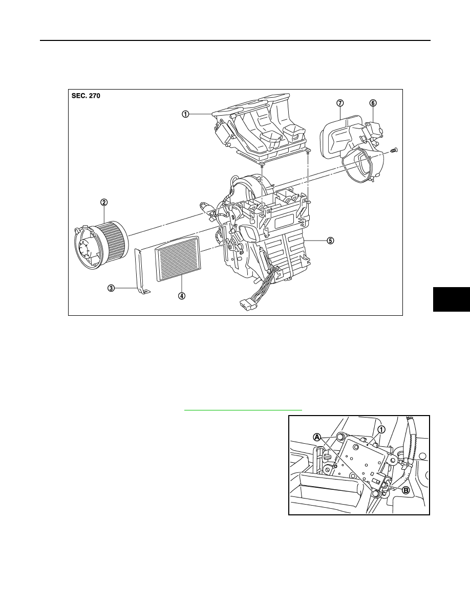
Exploded View
INFOID:0000000001093846
Removal and Installation
INFOID:0000000001093847
REMOVAL
1.
Remove Instrument Panel. Refer to
IP-12, "Removal and Installation"
2.
Disconnect intake door motor connector (B).
3.
Remove harness connector fixing clip.
4.
Remove intake door motor fixing screws (A).
5.
Remove intake door motor (1).
INSTALLATION
Installation is basically the reverse order of removal.
1.
Hi-Level ventilation door unit assem-
bly
2.
Blower motor assembly
3.
Filter cover
4.
In-cabin microfilter
5.
Blower unit
6.
Intake door motor
7.
Intake door unit assembly
E1IIA0002GB
E1IIA0017ZZ