Nissan Qashqai (2007-2010). Manual - part 853
BLOWER UNIT
VTL-77
< ON-VEHICLE REPAIR >
[MANUAL AIR CONDITIONER]
C
D
E
F
G
H
J
K
L
M
A
B
VTL
N
O
P
BLOWER UNIT
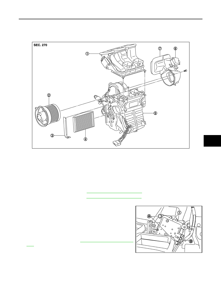
Exploded View
INFOID:0000000001093842
Removal and Installation
INFOID:0000000001093843
REMOVAL
1.
Remove Instrument Panel. Refer to
IP-12, "Removal and Installation"
2.
Remove steering member. Refer to
IP-12, "Removal and Installation"
3.
Remove Heater and cooling unit assembly.
4.
Remove harness fixing clip from upper intake box.
5.
Remove door motor harness connector (B).
6.
Remove lower intake box fixing screw from heater and cooling
case.
7.
Remove intake door motor (1).
• Remove fixing screws (A)
• Remove bracket support fixing screws and bracket support
8.
Remove blower motor.Refer to
VTL-79, "Removal and Installa-
CAUTION:
Move blower unit rightward, and remove locating pin (1
part) and joint. Then remove blower unit downward.
INSTALLATION
Installation is basically the reverse order of removal.
CAUTION:
1.
Hi-Level ventilation door unit assem-
bly
2.
Blower motor assembly
3.
Filter cover
4.
In-cabin microfilter
5.
Blower unit
6.
Intake door motor
7.
Intake door unit assembly
E1IIA0002GB
E1IIA0017ZZ