Nissan Qashqai (2007-2010). Manual - part 725


  Index      Nissan     Nissan Qashqai - service and repair manual 2007 - 2010 year


Search            copyright infringement  


Content   ..  723  724  725  726   ..


Nissan Qashqai (2007-2010). Manual - part 725


BRC-98

< FUNCTION DIAGNOSIS >

[ESP/TCS/ABS]

DIAGNOSIS SYSTEM [ABS ACTUATOR AND ELECTRIC UNIT (CONTROL 

UNIT)]

NOTE:

Every 20 seconds momentary switch to OFF.

ACTIVE TEST MODE

CAUTION:

• Do not perform active test while driving vehicle.
• Make sure to completely bleed air from brake system.
• The active test cannot be performed with the ABS warning lamp, ESP OFF indicator lamp, SLIP indi-

cator lamp and brake warning lamp are on.

• ABS warning lamp, ESP OFF indicator lamp, SLIP indicator lamp and brake warning lamp are on dur-

ing active test.

• Erase memory of ICC system after implementing active test.
NOTE:
• When active test is performed while depressing the pedal, the pedal depression amount will change. This is

normal. (Only solenoid valve and ABS motor.)

• “TEST IS STOPPED” is displayed 10 seconds after operation start.
• After “TEST IS STOPPED” is displayed, to perform test again.
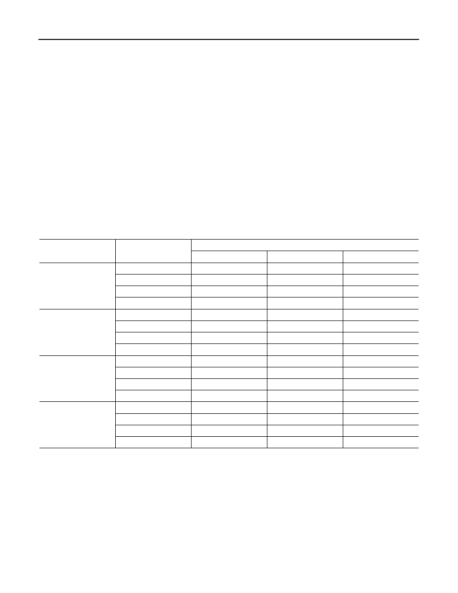
Test Item

ABS SOLENOID VALVE

• For ABS solenoid valve, touch “UP”, “KEEP” and “DOWN”. Then use screen monitor to check that solenoid

valve operates as shown in the table below.

*: ON for 1 to 2 seconds after the touch, and then OFF.

NOTE:

A brief moment of ON/OFF condition occurs every 20 seconds after ignition switch turned ON. This is malfunction because it is an
operation for checking.

ABS SOLENOID VALVE (ACT)

• For ABS solenoid valve (ACT), touch “UP”, “ACT UP” and “ACT KEEP”. Then use screen monitor to check

that solenoid valve operates as shown in the table below.

Test item

Display item

Display

UP

KEEP

DOWN

FR RH SOL

FR RH IN SOL

OFF

ON

ON

FR RH OUT SOL

OFF

OFF

ON*

USV [FR-RL]

OFF

OFF

OFF

HSV [FR-RL]

OFF

OFF

OFF

FR LH SOL

FR LH IN SOL

OFF

ON

ON

FR LH OUT SOL

OFF

OFF

ON*

USV [FL-RR]

OFF

OFF

OFF

HSV [FL-RR]

OFF

OFF

OFF

RR RH SOL

RR RH IN SOL

OFF

ON

ON

RR RH OUT SOL

OFF

OFF

ON*

USV [FL-RR]

OFF

OFF

OFF

HSV [FL-RR]

OFF

OFF

OFF

RR LH SOL

RR LH IN SOL

OFF

ON

ON

RR LH OUT SOL

OFF

OFF

ON*

USV [FR-RL]

OFF

OFF

OFF

HSV [FR-RL]

OFF

OFF

OFF

DIAGNOSIS SYSTEM [ABS ACTUATOR AND ELECTRIC UNIT (CONTROL 

UNIT)]

BRC-99

< FUNCTION DIAGNOSIS >

[ESP/TCS/ABS]

C

D

E

G

H

I

J

K

L

M

A

B

BRC

N

O

P

*: ON for 1 to 2 seconds after the touch, and then OFF.

NOTE:

A brief moment of ON/OFF condition occurs every 20 seconds after ignition switch turned ON. This is malfunction because it is an
operation for checking.

ABS MOTOR

• Touch “ON” and “OFF” on screen. Make sure motor relay and actuator relay operates as shown in table

below.

NOTE:

A brief moment of ON/OFF condition occurs every 20 seconds after ignition switch turned ON. This is not malfunction because it is an
operation for checking.

Test item

Display item

Display

UP

KEEP

DOWN

FR RH SOL

FR RH IN SOL

OFF

OFF

OFF

FR RH OUT SOL

OFF

OFF

OFF

USV [FR-RL]

OFF

ON

ON

HSV [FR-RL]

OFF

ON*

OFF

FR LH SOL

FR LH IN SOL

OFF

OFF

OFF

FR LH OUT SOL

OFF

OFF

OFF

USV [FL-RR]

OFF

ON

ON

HSV [FL-RR]

OFF

ON*

OFF

RR RH SOL

RR RH IN SOL

OFF

OFF

OFF

RR RH OUT SOL

OFF

OFF

OFF

USV [FL-RR]

OFF

ON

ON

HSV [FL-RR]

OFF

ON*

OFF

RR LH SOL

RR LH IN SOL

OFF

OFF

OFF

RR LH OUT SOL

OFF

OFF

OFF

USV [FR-RL]

OFF

ON

ON

HSV [FR-RL]

OFF

ON*

OFF

Test item

Display item

Display

ON

OFF

ABS MOTOR

MOTOR RELAY

ON

OFF

ACTUATOR RLY 

NOTE

ON

ON

BRC-100

< COMPONENT DIAGNOSIS >

[ESP/TCS/ABS]

C1101, C1102, C1103, C1104 WHEEL SENSOR-1

COMPONENT DIAGNOSIS

C1101, C1102, C1103, C1104 WHEEL SENSOR-1

Description

INFOID:0000000000924812

When the sensor rotor rotates, the magnetic field changes. The sensor converts the magnetic field changes to
current signals (rectangular wave) and transmits them to the ABS actuator and electric unit (control unit). 

DTC Logic

INFOID:0000000000924813

DTC DETECTION LOGIC

DTC CONFIRMATION PROCEDURE

1.

CHECK SELF-DIAGNOSIS RESULTS

Check the self-diagnosis results.

Is above displayed on the self-diagnosis display?

YES

>> Proceed to diagnosis procedure. Refer to 

BRC-100, "Diagnosis Procedure"

.

NO

>> INSPECTION END

Diagnosis Procedure

INFOID:0000000000924814

CAUTION:

Do not check between wheel sensor terminals.

INSPECTION PROCEDURE

1.

CHECK SENSOR AND SENSOR ROTOR

• Check sensor rotor for damage. 
• Check wheel sensor for damage, disconnection or looseness.
Are the sensor and sensor rotor normal?

YES

>> GO TO 2.

NO

>> Repair wheel sensor mount or replace sensor rotor. Then perform the self-diagnosis.

2.

CHECK CONNECTOR

1.

Turn ignition switch OFF.

2.

Disconnect ABS actuator and electric unit (control unit) connector.

3.

Disconnect malfunctioning wheel sensor connector.

4.

Check terminal for deformation, disconnection, looseness, and so on. If any malfunction is found, repair or
replace terminal.

DTC

Display item

Malfunction detected condition

Possible cause

C1101

RR RH SENSOR-1

Circuit of rear RH wheel sensor is open or short circuit. 
Current signal from sensor is outside limits.

• Harness or connector
• Wheel sensor
• ABS actuator and electric unit 

(control unit)

C1102

RR LH SENSOR-1

Circuit of rear LH wheel sensor is open or short circuit. 
Current signal from sensor is outside limits.

C1103

FR RH SENSOR-1

Circuit of front RH wheel sensor is open or short circuit. 
Current signal from sensor is outside limits.

C1104

FR LH SENSOR-1

Circuit of front LH wheel sensor is open or short circuit. 
Current signal from sensor is outside limits.

Self-diagnosis results

RR RH SENSOR-1

RR LH SENSOR-1

FR RH SENSOR-1

FR LH SENSOR-1

C1101, C1102, C1103, C1104 WHEEL SENSOR-1

BRC-101

< COMPONENT DIAGNOSIS >

[ESP/TCS/ABS]

C

D

E

G

H

I

J

K

L

M

A

B

BRC

N

O

P

5.

Reconnect connectors and then perform the self-diagnosis. Refer to 

BRC-96, "CONSULT-III Function

(ABS)"

.

Is any item indicated on the self-diagnosis display?

YES

>> GO TO 3.

NO

>> Poor connection of connector terminal. Repair or replace connector.

3.

CHECK WHEEL SENSOR HARNESS

1.

Turn ignition switch OFF.

2.

Disconnect ABS actuator and electric unit (control unit) connector.

3.

Disconnect malfunctioning wheel sensor connector.

4.

Check continuity between terminals. (Also check continuity when steering wheel is turned right and left
and when sensor harness inside the wheel house is moved.)

Measurement terminal for power supply circuit

Measurement terminal for signal circuit

Measurement terminal for ground circuit

5.

Reconnect ABS actuator and electric unit (control unit) connector.

Is the inspection result normal?

YES

>> GO TO 4.

NO

>> Repair or replace malfunctioning components.

4.

CHECK WHEEL SENSOR POWER SUPPLY CIRCUIT

1.

Turn ignition switch ON.

2.

Check voltage between wheel sensor harness connector power supply terminal and ground.

Is the inspection result normal?

ABS actuator and electric unit (control unit)

Wheel sensor

Continuity

Connector

Terminal

Connector

Terminal

E36

9

E39 (Front RH)

2

Existed

16

E22 (Front LH)

8

B41 (Rear RH)

6

B44 (Rear LH)

ABS actuator and electric unit (control unit)

Wheel sensor

Continuity

Connector

Terminal

Connector

Terminal

E36

10

E39 (Front RH)

1

Existed

5

E22 (Front LH)

19

B41 (Rear RH)

17

B44 (Rear LH)

ABS actuator and electric unit (control unit)

Continuity

Connector

Terminal

Connector

Terminal

E36

10, 9

E36

1, 4

Not existed

5, 16

19, 8

17, 6

Wheel sensor

Voltage

Connector

Terminal

E39 (Front RH)

2

Ground

8 V or more

E22 (Front LH)

B41 (Rear RH)

B44 (Rear LH)


Content   ..  723  724  725  726   ..