Nissan Qashqai (2007-2010). Manual - part 647


  Index      Nissan     Nissan Qashqai - service and repair manual 2007 - 2010 year


Search            copyright infringement  


Content   ..  645  646  647  648   ..


Nissan Qashqai (2007-2010). Manual - part 647


FAX-10

< ON-VEHICLE REPAIR >

[2WD]

FRONT WHEEL HUB AND KNUCKLE
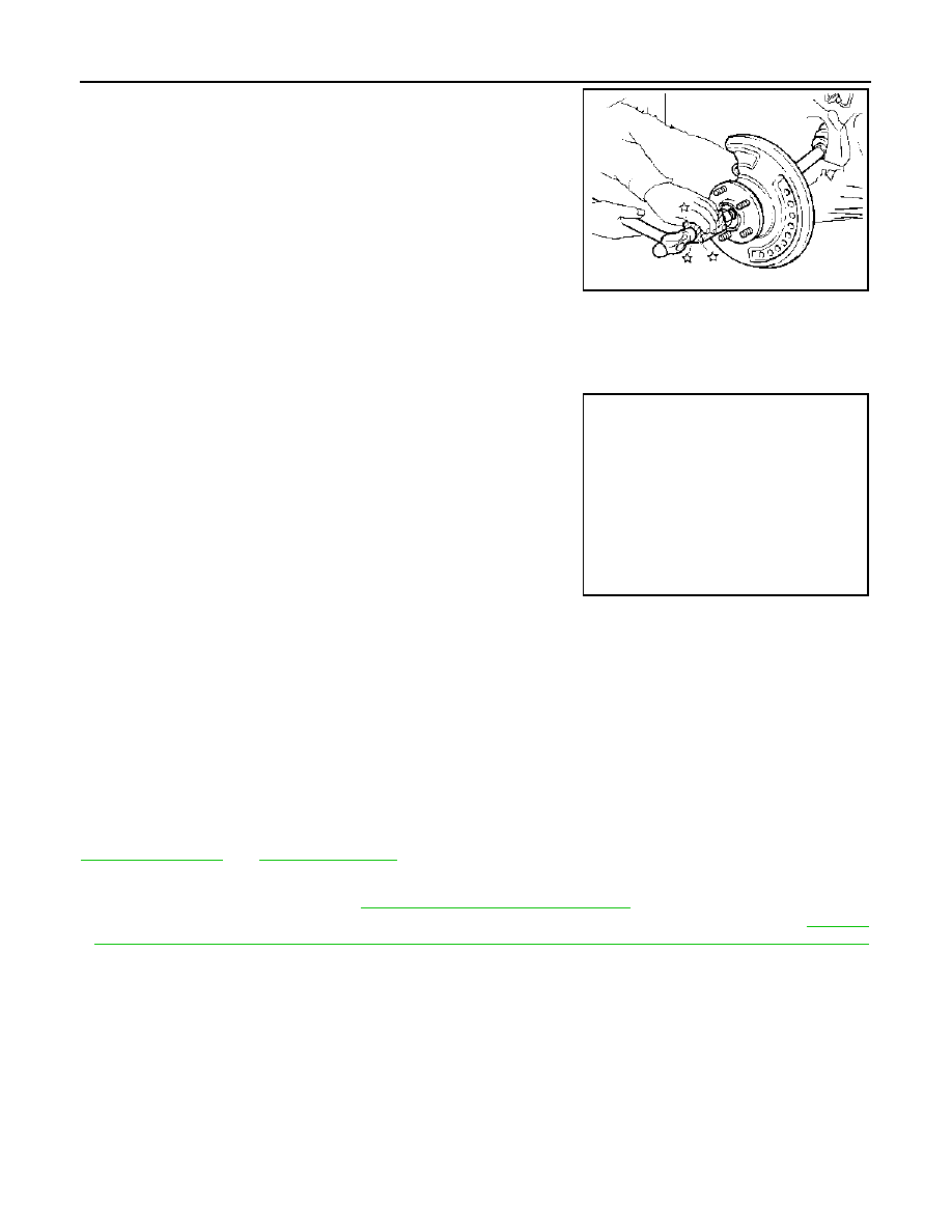
7.

Patch hub lock nut with a piece of wood. Hammer the wood to
disengage wheel hub and bearing assembly from drive shaft.
Remove the hub lock nut.

CAUTION:

• Never place drive shaft joint at an extreme angle. Also be

careful not to overextend slide joint.

• Never allow drive shaft to hang down without support for

housing (or joint sub-assembly), shaft and the other parts.

NOTE:
Use suitable puller, if wheel hub and bearing assembly and drive
shaft cannot be separated even after performing the above pro-
cedure.

8.

Remove wheel hub and bearing assembly.

Steering Knuckle

1.

Remove wheel hub and bearing assembly, and then remove splash guard.

2.

Remove cotter pin (1) of steering outer socket, and then loosen
the nut.

3.

Remove steering outer socket (2) from steering knuckle (3)
using the ball joint remover so as not to damage ball joint boot
(4).

CAUTION:

Temporarily tighten the nut to prevent damage to threads
and to prevent the ball joint remover from suddenly coming
off.

4.

Remove transverse link from steering knuckle.

5.

Remove steering knuckle from strut assembly.

6.

Remove steering knuckle form vehicle.

INSTALLATION

Note the following, and install in the reverse order of the removal.
• Under unladen conditions perform the final tightening of each parts removed when removing wheel hub and

bearing assembly and steering knuckle.

Inspection

INFOID:0000000000970483

INSPECTION AFTER REMOVAL

Check components for deformation, cracks, and other damage. Replace if there are.

Ball Joint Inspection

Check boots of transverse link and steering outer socket ball joint for breakage, axial play, and torque. Refer to

FSU-6, "Inspection"

 and 

ST-16, "Inspection"

.

INSPECTION AFTER INSTALLATION

• Check the wheel alignment. Refer to 

FSU-7, "Wheel Alignment Inspection"

.

• Adjust neutral position of steering angle sensor after checking the wheel alignment. Refer to 

BRC-78,

"ADJUSTMENT OF STEERING ANGLE SENSOR NEUTRAL POSITION : Special Repair Requirement"

(with ESP).

JPDIF0003ZZ

JPDIF0024ZZ

FRONT DRIVE SHAFT BOOT

FAX-11

< ON-VEHICLE REPAIR >

[2WD]

C

E

F

G

H

I

J

K

L

M

A

B

FAX

N

O

P

FRONT DRIVE SHAFT BOOT

Exploded View

INFOID:0000000001078725

Refer to 

FAX-15, "HR16DE MODELS : Exploded View"

 (HR16DE models), 

FAX-22, "MR20DE MODELS :

Exploded View"

 (MR20DE models), 

FAX-31, "K9K MODELS : Exploded View"

 (K9K models).

Replacement

INFOID:0000000000970485

WHEEL SIDE

1.

Remove tires from vehicle.

2.

Remove wheel sensor from steering knuckle. Refer to 

BRC-67, "FRONT WHEEL SENSOR : Exploded

View"

 (with ABS), 

BRC-172, "FRONT WHEEL SENSOR : Exploded View"

 (with ESP).

CAUTION:

Never pull on wheel sensor harness.

3.

Remove lock plate from strut assembly. Refer to 

BR-19, "FRONT BRAKE (WITH ABS) : Exploded View"

(LHD with ABS), 

BR-21, "FRONT BRAKE (WITH ESP) : Exploded View"

 (LHD with ESP), 

BR-63,

"FRONT BRAKE (WITH ABS) : Exploded View"

 (RHD with ABS), 

BR-65, "FRONT BRAKE (WITH ESP) :

Exploded View"

 (RHD with ESP).

4.

Remove torque member mounting bolts. Hang torque member not to interfere with work. Refer to 

BR-37,

"BRAKE CALIPER ASSEMBLY : Exploded View"

 (LHD), 

BR-81, "BRAKE CALIPER ASSEMBLY :

Exploded View"

 (RHD).

CAUTION:

Never depress brake pedal while brake caliper is removed.

5.

Remove disc rotor.

6.

Remove cotter pin, and then loosen hub lock nut.

7.

Patch hub lock nut with a piece of wood. Hammer the wood to
disengage wheel hub and bearing assembly from drive shaft.
Remove the hub lock nut.

CAUTION:

• Never place drive shaft joint at an extreme angle. Also be

careful not to overextend slide joint.

• Never allow drive shaft to hang down without support for

housing (or joint sub-assembly), shaft and the other parts.

NOTE:
Use suitable puller if wheel hub and drive shaft cannot be sepa-
rated even after performing the above procedure.

8.

Remove cotter pin (1) of steering outer socket, and then loosen
the nut.

9.

Remove steering outer socket (2) from steering knuckle (3) so
as not to damage ball joint boot (4) using the ball joint remover.

CAUTION:

Temporarily tighten the nut to prevent damage to threads
and to prevent the ball joint remover from suddenly coming
off.

10. Remove transverse link from steering knuckle.

11. Remove drive shaft from wheel hub and bearing assembly.
12. Remove boot bands, and then remove boot from joint sub-

assembly.

JPDIF0003ZZ

JPDIF0024ZZ

FAX-12

< ON-VEHICLE REPAIR >

[2WD]

FRONT DRIVE SHAFT BOOT

13. Screw a drive shaft puller (A) into joint sub-assembly screw part

to a length of 30 mm (1.18 in) or more. Support drive shaft with
one hand and pull out joint sub-assembly with a sliding hammer
(B) from shaft.

CAUTION:

• Align a sliding hammer and drive shaft and remove them

by pulling firmly and uniformly.

• If joint sub-assembly cannot be pulled out, try after

removing drive shaft from vehicle.

14. Remove circular clip (1) from shaft.
15. Remove boot from shaft.

16. Clean the old grease on joint sub-assembly with paper towels.

17. Fill serration slot joint sub-assembly (1) with NISSAN genuine

grease or equivalent until the serration slot and ball groove
become full to the brim.

CAUTION:

After applying grease, use a shop cloth to wipe off old
grease that has oozed out.

18. Wrap serration on shaft with tape (A) to protect the boot from

damage. Install boot and boot bands to shaft.

CAUTION:

Never reuse boot and boot band.

19. Remove the tape wrapped around the serration on shaft.

20. Position the circular clip (1) on groove at the shaft edge.

CAUTION:

Never reuse circular clip.
NOTE:
Drive joint inserter is recommended when installing circular clip.

JPDIF0022ZZ

JPDIF0007ZZ

JPDIF0008ZZ

JPDIF0009ZZ

JPDIF0010ZZ

FRONT DRIVE SHAFT BOOT

FAX-13

< ON-VEHICLE REPAIR >

[2WD]

C

E

F

G

H

I

J

K

L

M

A

B

FAX

N

O

P

21. Align both center axles of the shaft edge and joint sub-assembly. Then assemble shaft with circular clip

joint sub-assembly.

22. Install joint sub-assembly (1) to shaft using plastic hammer.

CAUTION:

Confirm that joint sub-assembly is correctly engaged while
rotating drive shaft.

23. Apply the balance of the specified amount of grease into the

boot inside from large diameter side of boot.

24. Install the boot securely into grooves (indicated by “*” marks)

shown in the figure.

CAUTION:

If grease adheres to the boot mounting surface (with “*”
mark) on the shaft or joint sub-assembly, boot may be
removed. Remove all grease from the surface.

25. To prevent from the deformation of the boot, adjust the boot

installation length to the specified value shown below (L) by
inserting the suitable tool into inside of the boot from the large
diameter side of the boot and discharging the inside air.

CAUTION:

• If the boot mounting length exceeds the standard, it may cause breakage in the boot.
• Be careful not to touch the inside of the boot with a tip of tool.

26. Secure the large and small ends of the boot with boot bands

using the boot band crimping tool (A) (SST: KV40107300).

NOTE:
Secure boot band so that dimension (M) meets the specification
as shown in the figure.

27. Secure joint sub-assembly and shaft, and then make sure that

they are in the correct position when rotating boot. Install them
with boot band when boot installation positions become incor-
rect.

28. Insert drive shaft to wheel hub and bearing assembly, and then

temporarily tighten hub lock nut.

CAUTION:

The drive shaft is press-fit. When assembling the shaft, never press it, but pull it until fully seated
by tightening the hub lock nut.

Standard

Grease amount

: Refer to 

FAX-40, "Drive Shaft"

.

JPDIF0011ZZ

Standard

Boots installed 
length (L)

: Refer to 

FAX-40, "Drive Shaft"

.

JPDIF0018ZZ

JPDIF0012ZZ

Dimension “M”

: 1.0 – 4.0 mm (0.039 – 0.157 in)

DSF0047D


Content   ..  645  646  647  648   ..