Nissan Qashqai (2007-2010). Manual - part 1778


  Index      Nissan     Nissan Qashqai - service and repair manual 2007 - 2010 year


Search            copyright infringement  


Content   ..  1776  1777  1778  1779   ..


Nissan Qashqai (2007-2010). Manual - part 1778


LAN

MAIN LINE BETWEEN TCM AND BCM CIRCUIT

LAN-1137

< COMPONENT DIAGNOSIS >

[CAN SYSTEM (TYPE 78)]

C

D

E

F

G

H

I

J

K

L

B

A

O

P

N

MAIN LINE BETWEEN TCM AND BCM CIRCUIT

Diagnosis Procedure

INFOID:0000000001058230

INSPECTION PROCEDURE

1.

CHECK CONNECTOR

1.

Turn the ignition switch OFF.

2.

Disconnect the battery cable from the negative terminal.

3.

Check the following terminals and connectors for damage, bend and loose connection (connector side
and harness side).

-

Harness connector E105

-

Harness connector M77

Is the inspection result normal?

YES

>> GO TO 2.

NO

>> Repair the terminal and connector.

2.

CHECK HARNESS CONTINUITY (OPEN CIRCUIT)

1.

Disconnect the following harness connectors.

-

Harness connector F121 and E7

-

Harness connector E105 and M77

2.

Check the continuity between the harness connectors.

Is the inspection result normal?

YES

>> GO TO 3.

NO

>> Repair the main line between the harness connectors E7 and E105.

3.

CHECK HARNESS CONTINUITY (OPEN CIRCUIT)

1.

Disconnect the connector of BCM.

2.

Check the continuity between the harness connector and the BCM harness connector.

Is the inspection result normal?

YES (Present error)>>Check CAN system type decision again.
YES (Past error)>>Error was detected in the main line between the TCM and the BCM. 
NO

>> Repair the main line between the harness connector M77 and the BCM.
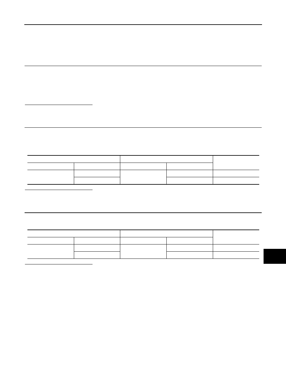
Harness connector

Harness connector

Continuity

Connector No.

Terminal No.

Connector No.

Terminal No.

E7

2

E105

52

Existed

1

51

Existed

Harness connector

BCM harness connector

Continuity

Connector No.

Terminal No.

Connector No.

Terminal No.

M77

52

M65

19

Existed

51

20

Existed

LAN-1138

< COMPONENT DIAGNOSIS >

[CAN SYSTEM (TYPE 78)]

MAIN LINE BETWEEN BCM AND DLC CIRCUIT

MAIN LINE BETWEEN BCM AND DLC CIRCUIT

Diagnosis Procedure

INFOID:0000000001058231

INSPECTION PROCEDURE

1.

CHECK HARNESS CONTINUITY (OPEN CIRCUIT)

1.

Turn the ignition switch OFF.

2.

Disconnect the battery cable from the negative terminal.

3.

Disconnect the following harness connectors.

-

ECM

-

BCM

4.

Check the continuity between the BCM harness connector and the data link connector.

Is the inspection result normal?

YES (Present error)>>Check CAN system type decision again.
YES (Past error)>>Error was detected in the main line between the BCM and the data link connector. 
NO

>> Repair the main line between the BCM and the data link connector.

BCM harness connector

Data link connector

Continuity

Connector No.

Terminal No.

Connector No.

Terminal No.

M65

19

M4

6

Existed

20

14

Existed

LAN

ECM BRANCH LINE CIRCUIT

LAN-1139

< COMPONENT DIAGNOSIS >

[CAN SYSTEM (TYPE 78)]

C

D

E

F

G

H

I

J

K

L

B

A

O

P

N

ECM BRANCH LINE CIRCUIT

Diagnosis Procedure

INFOID:0000000001058235

1.

CHECK CONNECTOR

1.

Turn the ignition switch OFF.

2.

Disconnect the battery cable from the negative terminal.

3.

Check the terminals and connectors of the ECM for damage, bend and loose connection (unit side and
connector side).

Is the inspection result normal?

YES

>> GO TO 2.

NO

>> Repair the terminal and connector.

2.

CHECK HARNESS FOR OPEN CIRCUIT

1.

Disconnect the connector of ECM.

2.

Check the resistance between the ECM harness connector terminals.

-

HR engine/MR engine models

-

K9K engine models

Is the measurement value within the specification?

YES

>> GO TO 3.

NO

>> Repair the ECM branch line.

3.

CHECK POWER SUPPLY AND GROUND CIRCUIT

Check the power supply and the ground circuit of the ECM. Refer to the following.
• HR16DE (With EURO-OBD): 

EC-117, "Diagnosis Procedure"

• HR16DE (Without EURO-OBD): 

EC-446, "Diagnosis Procedure"

• MR20DE (With EURO-OBD): 

EC-736, "Diagnosis Procedure"

• MR20DE (Without EURO-OBD): 

EC-1069, "Diagnosis Procedure"

• K9K: 

EC-1317, "Diagnosis Procedure"

Is the inspection result normal?

YES (Present error)>>•Replace the ECM. Refer to the following.

- HR16DE (With EURO-OBD): 

EC-29, "ADDITIONAL SERVICE WHEN REPLACING CONTROL

UNIT : Special Repair Requirement"

HR16DE (Without EURO-OBD): 

EC-368, "ADDITIONAL SERVICE WHEN REPLACING CON-

TROL UNIT : Special Repair Requirement"

- MR20DE (With EURO-OBD): 

EC-645, "ADDITIONAL SERVICE WHEN REPLACING CON-

TROL UNIT : Special Repair Requirement"

- MR20DE (Without EURO-OBD): 

EC-989, "ADDITIONAL SERVICE WHEN REPLACING CON-

TROL UNIT : Special Repair Requirement"

- K9K: 

EC-1273, "ADDITIONAL SERVICE WHEN REPLACING CONTROL UNIT : Special Repair

Requirement"

YES (Past error)>>Error was detected in the ECM branch line.
NO

>> Repair the power supply and the ground circuit.

ECM harness connector

Resistance (

)

Connector No.

Terminal No.

E16

84

83

Approx. 108 – 132

ECM harness connector

Resistance (

)

Connector No.

Terminal No.

E60

100

99

Approx. 108 – 132

LAN-1140

< COMPONENT DIAGNOSIS >

[CAN SYSTEM (TYPE 78)]

ABS BRANCH LINE CIRCUIT

ABS BRANCH LINE CIRCUIT

Diagnosis Procedure

INFOID:0000000001058236

1.

CHECK CONNECTOR

1.

Turn the ignition switch OFF.

2.

Disconnect the battery cable from the negative terminal.

3.

Check the terminals and connectors of the ABS actuator and electric unit (control unit) for damage, bend
and loose connection (unit side and connector side).

Is the inspection result normal?

YES

>> GO TO 2.

NO

>> Repair the terminal and connector.

2.

CHECK HARNESS FOR OPEN CIRCUIT

1.

Disconnect the connector of ABS actuator and electric unit (control unit).

2.

Check the resistance between the ABS actuator and electric unit (control unit) harness connector termi-
nals.

-

Models with ESP

-

Models with ABS

Is the measurement value within the specification?

YES

>> GO TO 3.

NO

>> Repair the ABS actuator and electric unit (control unit) branch line.

3.

CHECK POWER SUPPLY AND GROUND CIRCUIT

Check the power supply and the ground circuit of the ABS actuator and electric unit (control unit). Refer to the
following.
• ABS models: 

BRC-26, "Diagnosis Procedure"

• ESP models: 

BRC-106, "Diagnosis Procedure"

Is the inspection result normal?

YES (Present error)>>•Replace the ABS actuator and electric unit (control unit). Refer to 

BRC-70, "Exploded

View"

.

YES (Past error)>>Error was detected in the ABS actuator and electric unit (control unit) branch line.
NO

>> Repair the power supply and the ground circuit.

ABS actuator and electric unit (control unit) harness connector

Resistance (

)

Connector No.

Terminal No.

E36

26

15

Approx. 54 – 66

ABS actuator and electric unit (control unit) harness connector

Resistance (

)

Connector No.

Terminal No.

E34

26

15

Approx. 54 – 66


Content   ..  1776  1777  1778  1779   ..