Nissan Qashqai (2007-2010). Manual - part 1776


  Index      Nissan     Nissan Qashqai - service and repair manual 2007 - 2010 year


Search            copyright infringement  


Content   ..  1774  1775  1776  1777   ..


Nissan Qashqai (2007-2010). Manual - part 1776


LAN

M&A BRANCH LINE CIRCUIT

LAN-1129

< COMPONENT DIAGNOSIS >

[CAN SYSTEM (TYPE 77)]

C

D

E

F

G

H

I

J

K

L

B

A

O

P

N

M&A BRANCH LINE CIRCUIT

Diagnosis Procedure

INFOID:0000000001058190

INSPECTION PROCEDURE

1.

CHECK CONNECTOR

1.

Turn the ignition switch OFF.

2.

Disconnect the battery cable from the negative terminal.

3.

Check the terminals and connectors of the combination meter for damage, bend and loose connection
(unit side and connector side).

Is the inspection result normal?

YES

>> GO TO 2.

NO

>> Repair the terminal and connector.

2.

CHECK HARNESS FOR OPEN CIRCUIT

1.

Disconnect the connector of combination meter.

2.

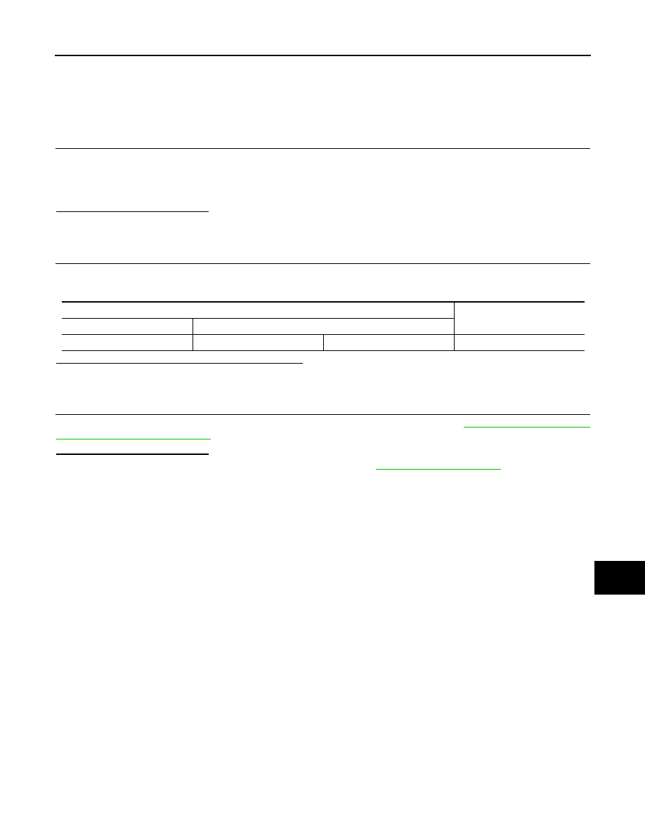
Check the resistance between the combination meter harness connector terminals.

Is the measurement value within the specification?

YES

>> GO TO 3.

NO

>> Repair the combination meter branch line.

3.

CHECK POWER SUPPLY AND GROUND CIRCUIT

Check the power supply and the ground circuit of the combination meter. Refer to  

MWI-28, "COMBINATION

METER : Diagnosis Procedure"

.

Is the inspection result normal?

YES (Present error)>>Replace the combination meter. Refer to  

MWI-72, "Exploded View"

.

YES (Past error)>>Error was detected in the combination meter branch line.
NO

>> Repair the power supply and the ground circuit.

Combination meter harness connector

Resistance (

)

Connector No.

Terminal No.

M34

21

22

Approx. 54 – 66

LAN-1130

< COMPONENT DIAGNOSIS >

[CAN SYSTEM (TYPE 77)]

DLC BRANCH LINE CIRCUIT

DLC BRANCH LINE CIRCUIT

Diagnosis Procedure

INFOID:0000000001058192

INSPECTION PROCEDURE

1.

CHECK CONNECTOR

1.

Turn the ignition switch OFF.

2.

Disconnect the battery cable from the negative terminal.

3.

Check the terminals and connectors of the data link connector for damage, bend and loose connection
(connector side and harness side).

Is the inspection result normal?

YES

>> GO TO 2.

NO

>> Repair the terminal and connector.

2.

CHECK HARNESS FOR OPEN CIRCUIT

Check the resistance between the data link connector terminals.

Is the measurement value within the specification?

YES (Present error)>>Check the CAN system type decision again.
YES (Past error)>>Error was detected in the data link connector branch line circuit.
NO

>> Repair the data link connector branch line.

Data link connector

Resistance (

)

Connector No.

Terminal No.

M4

6

14

Approx. 54 – 66

LAN

EPS BRANCH LINE CIRCUIT

LAN-1131

< COMPONENT DIAGNOSIS >

[CAN SYSTEM (TYPE 77)]

C

D

E

F

G

H

I

J

K

L

B

A

O

P

N

EPS BRANCH LINE CIRCUIT

Diagnosis Procedure

INFOID:0000000001058193

INSPECTION PROCEDURE

1.

CHECK CONNECTOR

1.

Turn the ignition switch OFF.

2.

Disconnect the battery cable from the negative terminal.

3.

Check the terminals and connectors of the EPS control unit for damage, bend and loose connection (unit
side and connector side).

Is the inspection result normal?

YES

>> GO TO 2.

NO

>> Repair the terminal and connector.

2.

CHECK HARNESS FOR OPEN CIRCUIT

1.

Disconnect the connector of EPS control unit.

2.

Check the resistance between the EPS control unit harness connector terminals.

Is the measurement value within the specification?

YES

>> GO TO 3.

NO

>> Repair the EPS control unit branch line.

3.

CHECK POWER SUPPLY AND GROUND CIRCUIT

Check the power supply and the ground circuit of the EPS control unit. Refer to 

STC-8, "Diagnosis Proce-

dure"

.

Is the inspection result normal?

YES (Present error)>>Replace the EPS control unit. Refer to 

ST-10, "Exploded View"

.

YES (Past error)>>Error was detected in the EPS control unit branch line.
NO

>> Repair the power supply and the ground circuit.

EPS control unit harness connector

Resistance (

)

Connector No.

Terminal No.

M37

8

6

Approx. 54 – 66

LAN-1132

< COMPONENT DIAGNOSIS >

[CAN SYSTEM (TYPE 77)]

STRG BRANCH LINE CIRCUIT

STRG BRANCH LINE CIRCUIT

Diagnosis Procedure

INFOID:0000000001058195

INSPECTION PROCEDURE

1.

CHECK CONNECTOR

1.

Turn the ignition switch OFF.

2.

Disconnect the battery cable from the negative terminal.

3.

Check the terminals and connectors of the steering angle sensor for damage, bend and loose connection
(unit side and connector side).

Is the inspection result normal?

YES

>> GO TO 2.

NO

>> Repair the terminal and connector.

2.

CHECK HARNESS FOR OPEN CIRCUIT

1.

Disconnect the connector of steering angle sensor.

2.

Check the resistance between the steering angle sensor harness connector terminals.

Is the measurement value within the specification?

YES

>> GO TO 3.

NO

>> Repair the steering angle sensor branch line.

3.

CHECK POWER SUPPLY AND GROUND CIRCUIT

Check the power supply and the ground circuit of the steering angle sensor. Refer to 

BRC-155, "Wiring Dia-

gram - BRAKE CONTROL SYSTEM -"

.

Is the inspection result normal?

YES (Present error)>>Replace the steering angle sensor. Refer to 

BRC-179, "Exploded View"

.

YES (Past error)>>Error was detected in the steering angle sensor branch line.
NO

>> Repair the power supply and the ground circuit.

Steering angle sensor harness connector

Resistance (

)

Connector No.

Terminal No.

M30

4

8

Approx. 54 – 66


Content   ..  1774  1775  1776  1777   ..