Nissan Qashqai (2007-2010). Manual - part 83
EM-280
< ON-VEHICLE REPAIR >
[K9K]
OIL PAN
OIL PAN
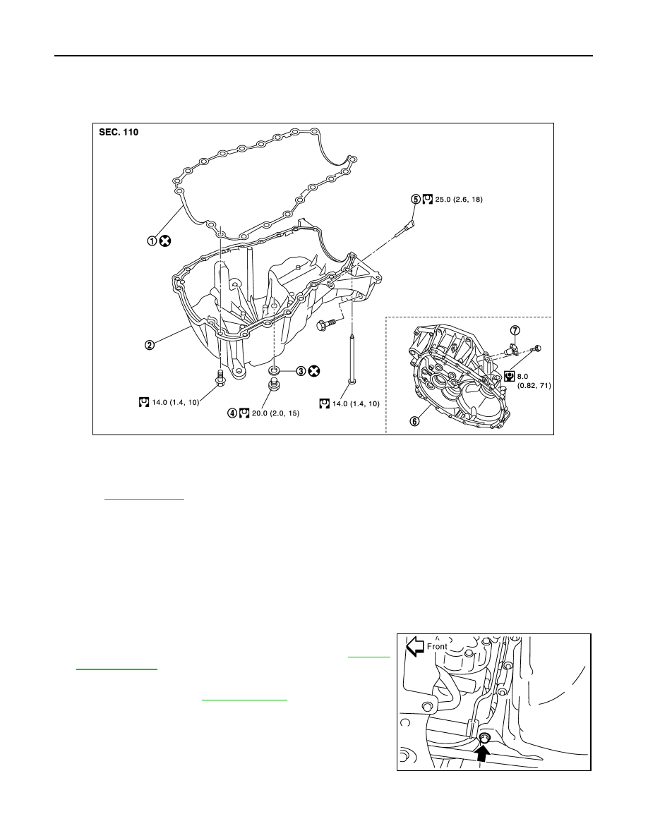
Exploded View
INFOID:0000000001060322
Removal and Installation
INFOID:0000000001060447
CAUTION:
To avoid the danger of being scalded, never drain the engine oil when the engine is hot.
REMOVAL
1.
Remove engine undercover.
2.
Remove RH front wheel.
3.
Remove right side splash cover.
4.
Remove multifunction bracket mounting bolt as shown.
5.
Remove bolts (3) from the catalyst bracket. Refer to
6.
Remove oil level sensor.
7.
Drain engine oil. Refer to
.
CAUTION:
Perform when engine is cold.
1.
Gasket
2.
Oil pan
3.
O-ring
4.
Drain plug
5.
Oil level sensor
6.
Clutch housing
7.
Crankshaft position sensor
Refer to
for symbols in the figure.
E1BIA0008GB
MBIB1038E