Nissan Qashqai (2007-2010). Manual - part 80
EM-268
< ON-VEHICLE REPAIR >
[K9K]
EGR SYSTEM
EGR SYSTEM
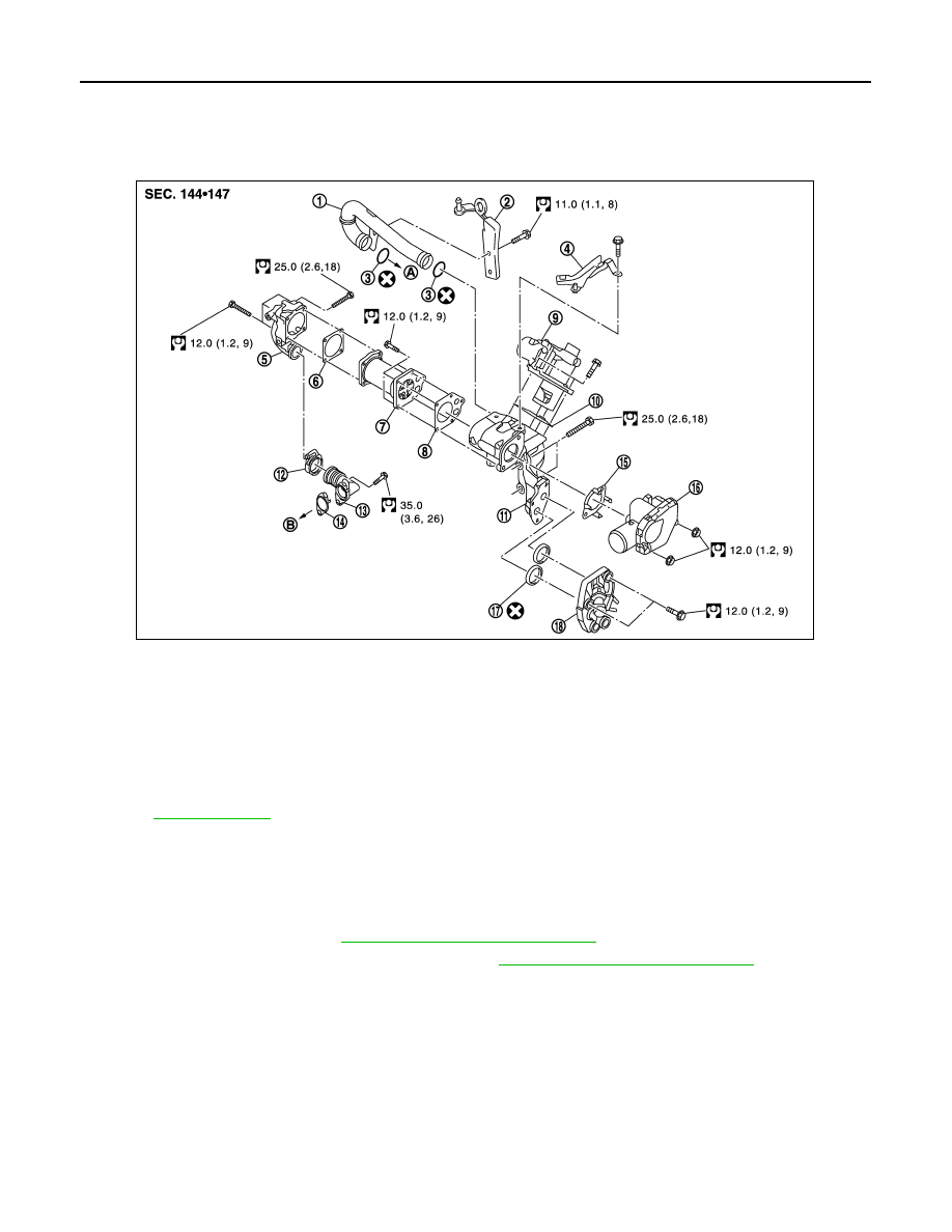
Exploded View
INFOID:0000000001060215
Removal and Installation
INFOID:0000000001060420
REMOVAL
1.
Remove battery ground cable.
2.
Remove engine cover. Refer to
EM-266, "Removal and Installation"
.
3.
Remove air cleaner case and air duct (inlet). Refer to
EM-265, "Removal and Installation"
.
4.
Remove bulk head cover.
5.
Disconnect EGR volume control valve connector.
6.
Remove mounting bolts.
7.
Drain engine coolant and disconnect water hose.
8.
Loosen turbocharger inlet tube.
9.
Remove front engine slinger..
10. Remove air inlet tube.
11. Remove electric throttle control actuator.
12. Remove EGR tube mounting bolts.
1.
Air inlet tube
2.
Engine slinger
3.
O-ring
4.
Bracket
5.
EGR tube
6.
Gasket
7.
EGR cooler
8.
Gasket
9.
EGR volume control valve
10. Gasket
11.
EGR volume control valve housing
12. Clamp
13. EGR tube
14. Gasket
15. Gasket
16. Electric throttle control actuator
17. O-ring
18. EGR cooler cover
A.
To intake manifold
B.
To exhaust manifold
Refer to
for symbols in the figure.
E1BIA0025GB