Hyundai Veloster (2019 year). Manual - part 25

Maintenance
Temperature - A, B & C
Tire Terminology and
WARNING
The temperature grades are A (the
Definitions
highest), B and C representing the
The temperature grade for this
Air Pressure
tire’s resistance to the generation of
tire is established for a tire that
The amount of air inside the tire
heat and its ability to dissipate heat
is properly inflated and not
pressing outward on the tire. Air
when tested under controlled condi-
overloaded. Excessive speed,
pressure is expressed in pounds per
tions on a specified indoor laboratory
under-inflation, over-inflation,
square inch (psi) or kilopascal (kPa).
test wheel.
or excessive loading, either
Sustained high temperature can
separately or in combination,
cause the material of the tire to
can cause heat build-up and
Accessory Weight
degenerate and reduce tire life, and
possible sudden tire failure.
This means the combined weight of
excessive temperature can lead to
This may cause loss of vehicle
optional accessories. Some exam-
sudden tire failure. Grade C
control resulting in an accident.
ples of optional accessories are
responds to a level of performance
automatic transmission, power
which all passenger car tires must
seats, and air conditioning.
meet under the Federal Motor
Vehicle Safety Standard No.
109.
Aspect Ratio
Grades B and A represent higher
levels of performance on the labora-
The relationship of a tire's height to
tory test wheel than the minimum
its width.
required by law.
Belt
A rubber coated layer of cords that is
located between the plies and the
tread. Cords may be made from steel
or other reinforcing materials.
7-46
Bead
DOT Markings
Kilopascal (kPa)
The tire bead contains steel wires
A code molded into the sidewall of a
The metric unit for air pressure.
wrapped by steel cords that hold the
tire signifying that the tire is in com-
tire onto the rim.
pliance with the U.S. Department of
Light truck(LT) tire
Transportation motor vehicle safety
standards. The DOT code includes
A tire designated by its manufacturer
Bias Ply Tire
the Tire Identification Number (TIN),
as primarily intended for use on light-
A pneumatic tire in which the plies
an alphanumeric designator which
weight trucks or multipurpose pas-
are laid at alternate angles less than
can also identify the tire manufactur-
senger vehicles.
90 degrees to the centerline of the
er, production plant, brand and date
tread.
of production.
Load ratings
The maximum load that a tire is rated
Cold Tire Pressure
GVWR
to carry for a given inflation pressure.
The amount of air pressure in a tire,
Gross Vehicle Weight Rating
measured in pounds per square inch
Load Index
(psi) or kilopascals (kPa) before a tire
has built up heat from driving.
GAWR FRT
An assigned number ranging from 1
Gross Axle Weight Rating for the
to 279 that corresponds to the load
Front Axle.
carrying capacity of a tire.
Curb Weight
7
This means the weight of a motor
GAWR RR
Maximum Inflation Pressure
vehicle with standard and optional
equipment including the maximum
Gross Axle Weight Rating for the
The maximum air pressure to which
capacity of fuel, oil and coolant, but
Rear axle.
a cold tire may be inflated. The max-
without passengers and cargo.
imum air pressure is molded onto the
sidewall.
Intended Outboard Sidewall
The side of an asymmetrical tire, that
must always face outward when
mounted on a vehicle.
7-47
Maintenance
Maximum Load Rating
Passenger (P-Metric) tire
Recommended Inflation
The load rating for a tire at the maxi-
A tire used on passenger cars and
Pressure
mum permissible inflation pressure
some light duty trucks and multipur-
Vehicle manufacturer's recommend-
for that tire.
pose vehicles.
ed tire inflation pressure as shown
on the tire placard.
Maximum Loaded Vehicle
Ply
Weight
Radial Ply Tire
A layer of rubber-coated parallel
The sum of curb weight; accessory
cords.
A pneumatic tire in which the ply
weight; vehicle capacity weight; and
cords that extend to the beads are
production options weight.
laid at 90 degrees to the centerline of
Pneumatic tire
the tread.
A mechanical device made of rubber,
Normal Occupant Weight
chemicals, fabric and steel or other
Rim
The number of occupants a vehicle
materials, that, when mounted on an
is designed to seat multiplied by 150
automotive wheel provides the trac-
A metal support for a tire and upon
pounds (68 kg).
tion and contains the gas or fluid that
which the tire beads are seated.
sustains the load.
Occupant Distribution
Sidewall
Pneumatic options weight
Designated seating positions.
The portion of a tire between the
The combined weight of installed
tread and the bead.
regular production options weighing
Outward Facing Sidewall
over 5 lb. (2.3 kg) in excess of the
Speed Rating
An asymmetrical tire has a particular
standard items which they replace,
side that faces outward when mount-
not previously considered in curb
An alphanumeric code assigned to a
ed on a vehicle. The outward facing
weight or accessory weight, includ-
tire indicating the maximum speed at
sidewall bears white lettering or
ing heavy duty breaks, ride levelers,
which a tire can operate.
bears manufacturer, brand, and/or
roof rack, heavy duty battery, and
model name molding that is higher or
special trim.
deeper than the same moldings on
the inner facing sidewall.
7-48
Traction
Vehicle Capacity Weight
All Season Tires
The friction between the tire and the
The number of designated seating
HYUNDAI specifies all season tires
road surface. The amount of grip pro-
positions multiplied by 150 lbs. (68
on some models to provide good
vided.
kg) plus the rated cargo and luggage
performance for use all year round,
load.
including snowy and icy road condi-
tions. All season tires are identified
Tread
by ALL SEASON and/or M+S (Mud
Vehicle Maximum Load on the
The portion of a tire that comes into
and Snow) on the tire sidewall. Snow
contact with the road.
Tire
tires have better snow traction than
Load on an individual tire due to curb
all season tires and may be more
and accessory weight plus maximum
appropriate in some areas.
Treadwear Indicators
occupant and cargo weight.
Narrow bands, sometimes called
"wear bars", that show across the
Summer Tires
Vehicle Normal Load on the Tire
tread of a tire when only 2/32nds of
HYUNDAI specifies summer tires on
an inch of tread remains.
Load on an individual tire that is
some models to provide superior
determined by distributing to each
performance on dry roads. Summer
axle its share of the curb weight,
UTQGS
tire performance is substantially
accessory weight, and normal occu-
reduced in snow and ice. Summer
Uniform Tire Quality Grading
pant weight and dividing by 2.
tires do not have the tire traction rat-
Standards is a tire information sys-
ing M+S (Mud and Snow) on the tire
7
tem that provides consumers with
Vehicle Placard
side wall. If you plan to operate your
ratings for a tire's traction, tempera-
vehicle in snowy or icy conditions,
ture and treadwear. Ratings are
A label permanently attached to a
HYUNDAI recommends the use of
determined by tire manufacturers
vehicle showing the original equip-
snow tires or all season tires on all
using government testing proce-
ment tire size and recommended
four wheels.
dures. The ratings are molded into
inflation pressure.
the sidewall of the tire.
7-49

Maintenance
Snow Tires
Radial-ply tires have the same load
WARNING
carrying capacity, as bias-ply or bias
If you equip your car with snow tires,
belted tires of the same size, and use
they should be the same size and
Do not mix bias ply and radial
the same recommended inflation
have the same load capacity as the
ply tires under any circum-
pressure. Mixing of radial-ply tires
original tires. Snow tires should be
stances. This may cause unusu-
with bias-ply or bias belted tires is
installed on all four wheels; other-
al handling characteristics that
not recommended. Any combina-
wise, poor handling may result. Snow
may cause loss of vehicle con-
tions of radial-ply and bias-ply or bias
tires should carry
4 psi
(28 kPa)
trol resulting in an accident.
belted tires when used on the same
more air pressure than the pressure
vehicle will seriously deteriorate
recommended for the standard tires
vehicle handling. The best rule to fol-
on the tire label on the driver’s side of
low is: Identical pairs of radial-ply
Low Aspect Ratio Tires
the center pillar, or up to the maxi-
tires should always be used as a set
mum pressure shown on the tire
The aspect ratio is lower than 50 on
for the front tires and a set for the
sidewall, whichever is less. Do not
low aspect ratio tires.
rear tires.
drive faster than 75 mph (120 km/h)
Because low aspect ratio tires are
when your vehicle is equipped with
Longer wearing tires can be more
optimized for handling and braking,
snow tires.
susceptible to irregular tread wear. It
their sidewall is a little stiffer than a
is very important to follow the tire
standard tire. Also low aspect ratio
rotation interval in this chapter to
tires tend to be wider and conse-
Radial-Ply Tires
achieve the tread life potential of
quently have a greater contact patch
Radial-ply tires provide improved
these tires. Cuts and punctures in
with the road surface. In some
tread life, road hazard resistance and
radial-ply tires are repairable only in
instances they may generate more
smoother high speed ride. The radi-
the tread area, because of sidewall
road noise compared with standard
al-ply tires used on this vehicle are of
flexing. Consult your tire dealer for
tires.
belted construction, and are selected
radial-ply tire repairs.
to complement the ride and handling
characteristics of your vehicle.
7-50

CAUTION
CAUTION
Because the sidewall of a low
•
It is not easy to recognize tire
aspect ratio tire is shorter than
damage with your own eyes.
a standard tire, the rim of the
But if there is the slightest
wheel and the tire itself is more
hint of tire damage, have the
easily susceptible to damage.
tire checked or replaced
Use caution when driving and
because the tire damage may
follow the guidelines below to
cause air leakage from the
help minimize damage to the
tire.
wheel and tire:
•
If the tire is damaged by driv-
- When driving on a rough road
ing on a rough road, off road,
or off road, drive cautiously
pothole, manhole, or curb
because tires and wheels may
stone, it will not be covered by
be damaged. And after driving,
the warranty.
inspect tires and wheels.
- When passing over a pothole,
speed bump, manhole, or curb
stone, drive slowly so that the
tires and wheels are not dam-
7
aged.
- If the tire is subjected to a
severe impact, have the tire
and wheel inspected by an
authorized HYUNDAI dealer.
- Inspect the tire condition and
pressure every
1,800 miles
(3,000km).
7-51

Maintenance
FUSES
■ Blade type
If any of your vehicle's lights, acces-
WARNING
sories, or controls do not work, check
the appropriate circuit fuse. If a fuse
NEVER replace a fuse with any-
has blown, the element inside the
thing but another fuse of the
fuse will be melted or broken.
Normal
Blown
same rating.
If the electrical system does not
■ Cartridge type
• A higher capacity fuse could
work, first check the driver's side
cause damage and possibly
fuse panel. Before replacing a blown
cause a fire.
fuse, turn the engine and all switches
off, and then disconnect the negative
• Do not install a wire or alu-
battery cable. Always replace a
minum foil instead of the
blown fuse with one of the same rat-
proper fuse - even as a tem-
Normal
Blown
ing.
porary repair. It may cause
■ Multi fuse
extensive wiring damage and
If the replacement fuse blows, this
possibly a fire.
indicates an electrical problem. Avoid
using the system involved and imme-
diately consult an authorized
NOTICE
HYUNDAI dealer.
Do not use a screwdriver or any
Normal
Blown
other metal object to remove
OLF074075
fuses because it may cause a
short circuit and damage the sys-
A vehicle's electrical system is pro-
tem.
tected from electrical overload dam-
age by fuses.
This vehicle has 2 (or 3) fuse panels,
one located in the driver's side panel
bolster, the other in the engine com-
partment near the battery.
7-52

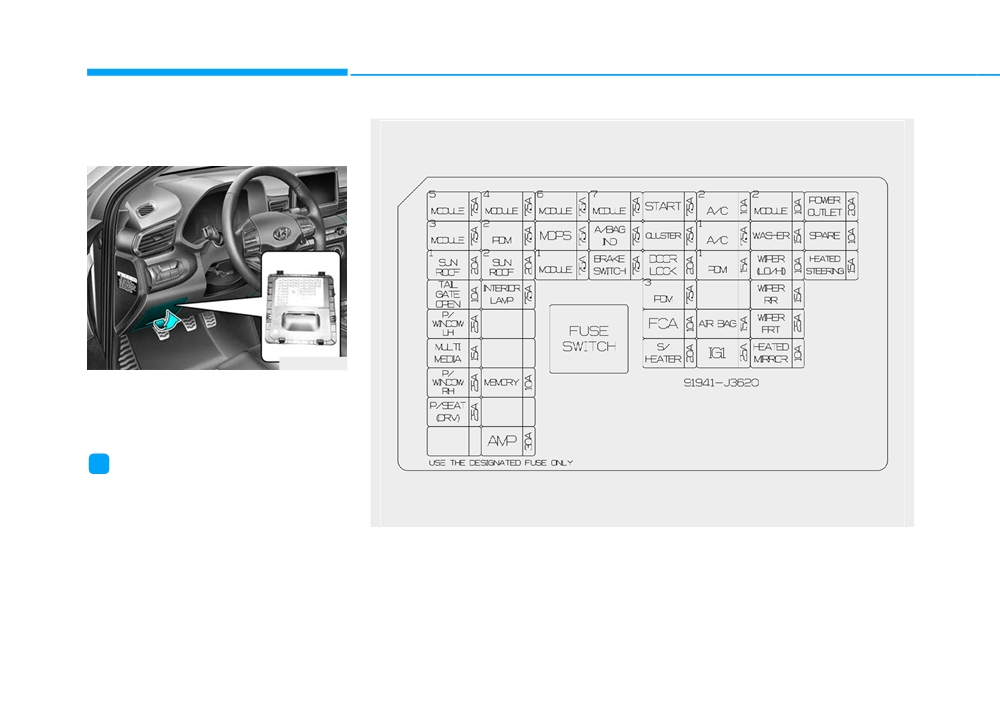
Instrument Panel Fuse
In an emergency, if you do not have
Replacement
a spare fuse, use a fuse of the same
rating from a circuit you may not
need for operating the vehicle.
If the headlamps or other electrical
components do not work and the
fuses are undamaged, check the
fuse panel in the engine compart-
ment. If a fuse is blown, it must be
replaced with the same rating.
OJS078051L
5. Pull the suspected fuse straight
out. Use the removal tool provided
OJS078022
in the engine compartment fuse
1. Turn the engine off.
panel.
2. Turn all other switches OFF.
6. Check the removed fuse; replace it
3. Open the fuse panel cover.
if it is blown. Spare fuses are pro-
vided in the instrument panel fuse
4. Refer to the label on the inside of
panels (or in the engine compart-
the fuse panel cover to locate the
7
ment fuse panel).
suspected fuse location.
7. Push in a new fuse of the same
rating, and make sure it fits tightly
in the clips. If it fits loosely, consult
an authorized HYUNDAI dealer.
7-53

Maintenance
Fuse switch
Engine Compartment Panel
i
Information
Fuse Replacement
■ Blade type fuse
OJS078023
OOS047142L
OJS078052L
Always, place the fuse switch to the
If the fuse switch is OFF, the above
ON position.
■ Cartridge type fuse
message will appear.
If you move the switch to the OFF
position, some items such as the
NOTICE
audio system and digital clock must
be reset and the smart key may not
• Always place the fuse switch in
work properly.
the ON position while driving the
vehicle.
• Do not move the fuse switch
repeatedly. The fuse switch may
be damaged.
OJS078053L
1. Turn the engine off.
2. Turn all other switches OFF.
7-54

3. Remove the fuse panel cover by
Main fuse
Multi fuse
pressing the tab and pulling up.
4. Check the removed fuse; replace it
if it is blown. To remove or insert
the fuse, use the fuse puller in the
engine compartment fuse panel.
5. Push in a new fuse of the same
rating, and make sure it fits tightly
in the clips. If it fits loosely, consult
an authorized HYUNDAI dealer.
CAUTION
OJS078061L
OJS078062L
After checking the fuse box in
If the main fuse is blown, it must be
If the multi fuse is blown, it must be
the engine compartment secure-
removed as follows:
removed as follows:
ly close the fuse box cover
1. Turn off the engine.
1. Turn off the engine.
inside the engine compartment,
2. Disconnect the negative battery
2. Disconnect the negative battery
until it clicks.
cable.
cable.
If the fuse box is not closed
3. Remove the fuse panel cover by
3. Remove the fuse panel cover by
properly, water may leak in side,
pressing the tab and pulling it up.
pressing the tab and pulling it up.
7
possibly causing a malfunction
4. Remove the nuts shown in the pic-
4. Remove the nuts shown in the pic-
with the electrical system.
ture above.
ture above.
5. Replace the fuse with a new one
5. Replace the fuse with a new one
of the same rating.
of the same rating.
6. Reinstall in the reverse order of
6. Reinstall in the reverse order of
removal.
removal.
i
Information
i
Information
If the main fuse is blown, consult an
If the multi fuse is blown, consult an
authorized HYUNDAI dealer.
authorized HYUNDAI dealer.
7-55
Maintenance
Fuse/Relay Panel Description
Instrument panel fuse panel
OJS078022
Inside the fuse/relay box cover, you
can find the fuse/relay label describ-
ing fuse/relay names and ratings.
i
Information
Not all fuse panel descriptions in this
manual may be applicable to your
vehicle; the information is accurate at
OJS078069N
the time of printing. When you inspect
the fuse box on your vehicle, refer to
the fuse box label.
7-56

Instrument panel fuse panel
Fuse Name
Fuse Rating
Protected Component
A/T Shift Lever IND., Electro Chromic Mirror, A/V & Navigation Head Unit,
MODULE5
7.5A
A/C Control Module, Crash Pad Switch, Front Seat Warmer Module, Audio
MODULE3
7.5A
Sport Mode Switch, BCM
SUNROOF1
20A
Sunroof Control Module (GLASS)
TAIL GATE
10A
Tail Gate Relay
OPEN
P/WINDOW
25A
Power Window LH Relay, Driver Safety Power Window Module
LH
MULTI MEDIA
15A
Keyboard, Audio, A/V & Navigation Head Unit
P/WINDOW
25A
Power Window RH Relay
RH
P/SEAT (DRV)
25A
Driver Seat Manual Switch
7
SPARE
-
Spare
Blind-Spot Collision Warning Unit LH/RH, Stop Lamp Switch,
MODULE4
7.5A
Parking Assist Buzzer, Lane Keeping Assist Unit
PDM2
7.5A
Smart Key Control Module, Immobilizer Module
SUNROOF2
20A
Sunroof Control Module (ROLLER)
7-57

Maintenance
Instrument panel fuse panel
Fuse Name
Fuse Rating
Protected Component
INTERIOR
Vanity Lamp LH/RH, Center Room Lamp, Luggage Lamp,
7.5A
LAMP
Overhead Console Lamp, Wireless Charger Unit
SPARE
-
Spare
SPARE
-
Spare
MEMORY
10A
A/C Control Module, Head Up Display, Instrument Cluster
SPARE
-
Spare
AMP
30A
AMP
MODULE6
7.5A
Smart Key Control Module, BCM
MDPS
7.5A
MDPS Unit
BCM, Rain Sensor, Ignition Key Interlock Switch, Hazard Switch,
MODULE1
7.5A
Data Link Connector
MODULE7
7.5A
Front Seat Warmer Module, PCB Block (A/Con Comp Relay)
A/BAG IND
7.5A
Instrument Cluster, Hazard Switch
BRAKE
7.5A
Stop Lamp Switch, Smart Key Control Module
SWITCH
7-58

Instrument panel fuse panel
Fuse Name
Fuse Rating
Protected Component
Transaxle Range Switch (DCT), ECM, Ignition Lock & Clutch Switch,
START
7.5A
E/R Junction Block (START #1 Relay, B/Alarm Relay),
Smart Key Control Module
CLUSTER
7.5A
Head Up Display, Instrument Cluster
DOOR LOCK
20A
ICM Relay Box (Twoturn Unlock Relay)
PDM3
7.5A
Start Stop Button Switch, Immobilizer Module
FCA
10A
Forward Collision Avoidance Assist Unit
S/HEATER
20A
Front Seat Warmer Module
A/C2
10A
-
A/C1
7.5A
A/C Control Module, E/R Junction Block (Blower Relay)
7
PDM1
15A
Smart Key Control Module
SPARE
-
Spare
AIR BAG
15A
SRS Control Module, Passenger Occupant Detection
IG1
25A
PCB Block(FUSE : ECU5, VACUUM PUMP, ABS3, TCU2)
7-59

Maintenance
Instrument panel fuse panel
Fuse Name
Fuse Rating
Protected Component
Wireless Charger Unit, Smart Key Control Module, Audio, Amp, Keyboard,
MODULE2
10A
A/V & Navigation Head Unit, USB Charge, Power Outside Mirror Switch, BCM
WASHER
15A
Multifunction Switch
WIPER
10A
BCM
(LO/HI)
WIPER RR
15A
Rear Wiper Relay, Rear Wiper Motor
WIPER FRT
25A
Front Wiper Motor, PCB Block (Front Wiper(Low) Relay)
HEATED
10A
Driver/Passenger Power Outside Mirror, A/C Control Module, ECM
MIRROR
POWER
20A
Front Power Outlet
OUTLET
SPARE
10A
Spare
HEATED
15A
BCM
STEERING
7-60

Engine compartment fuse panel
OPD077037L
Inside the fuse/relay box cover, you
can find the fuse/relay label describ-
ing fuse/relay names and ratings.
i
Information
Not all fuse panel descriptions in this
7
manual may be applicable to your
vehicle; the information is accurate at
the time of printing. When you inspect
OJS078072N
the fuse panel in your vehicle, refer to
the fuse panel label.
7-61

Maintenance
Engine compartment fuse panel
Fuse Name
Fuse Rating
Protected Component
ALT
150A
Alternator, E/R Junction Block (Fuse - MDPS, B/ALARM HORN, ABS1, ABS2)
MDPS
80A
MDPS Unit
B+5
60A
PCB Block ((Fuse - ECU4, ECU3, HORN, A/CON COMP (G4NH)), Engine Control Relay)
B+2
60A
IGPM ((Fuse - S/HEATER), IPS0, IPS1, IPS2)
B+3
60A
IGPM (IPS3, IPS4, IPS5, IPS6)
B+4
50A
IGPM (Fuse - P/WINDOW LH/RH, TAILGATE OPEN, SUNROOF1/2, AMP, P/SEAT(DRV))
COOLING
60A
E/R Junction Block (C/Fan2 Hi Relay) (G4FJ)
FAN1
REAR
40A
E/R Junction Block (Rear Heated Relay)
HEATED
BLOWER
40A
E/R Junction Block (Blower Relay)
W/O Smark Key : Ignition Switch
IG1
40A
With Smark Key : E/R Junction Block (PDM #2 Relay (ACC), PDM #3 Relay (IG1))
W/O Smark Key : E/R Junction Block (START #1 Relay), Ignition Switch
IG2
40A
With Smark Key : E/R Junction Block (START #1 Relay, PDM #4 Relay (IG2))
[G4FJ] : 1.6 T-GDI
[G4NH] : 2.0 MPI
7-62