Ford Focus RS (2011 year). Manual - part 108


  Index      Ford     Ford Focus RS - service repair manual (2011 year) in english


Search            


Content   ..  106  107  108  109   ..


Ford Focus RS (2011 year). Manual - part 108


Body Sheet Metal

Types of steel

Steel body panels are still the most important
materials used in the fabrication of stressed skin
vehicle bodies. In addition to the familiar types of
steel, reinforced high-strength and also
ultra-high-strength special steels are used in
vehicle body construction.

Types of steels are classified by their properties of
strength and elasticity.

• Normal strength steel has a minimum yield

strength of up to about 210 N/mm².

• High strength steels have a minimum yield

strength of about 150 to 600 N/mm².

• Ultra-high-strength steels have a minimum yield

strength of about 400 to 1200 N/mm².

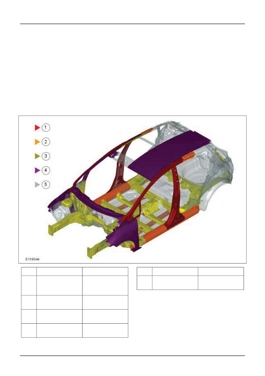
High-strength and ultra-high-strength steels are
mostly installed in safety relevant locations
(structural components). Among others, these are
side members, pillars, roof frames.

Application range

Used type of steel

Pos.

Impact carriers,

Bumper carriers,

Reinforcements ...

Ultra High Strengh

Steel (UHSS)

1

Frame side
member, ...

Extra High Strengh

Steel (EHSS)

2

Wheel house, ...

Very High Strengh

Steel (VHSS)

3

Roof sticks, ...

High Strengh Steel

(HSS)

4

Application range

Used type of steel

Pos.

Outer Panel, ...

Normal strength

steels

5

Normal strength steels

Normal strength steels are most often used in body
construction. They are relatively soft and are
therefore particularly suitable for the deep drawing
processes used in body manufacturing. As well as
very good reshaping properties, the panels also
have a relatively high rigidity.

G468068en

501-25-

19

Body Repairs - General Information

501-25-

19

DESCRIPTION AND OPERATION

High strength steel panels

The strength of the material and the nature of the
surface can be changed as required by different
engineering processes. In order to achieve suitable
configuration and a good match between
construction specifications and what is possible in
production, a large range of high strength panels
is available.

The range of the minimum yield strength is from
180 N/mm² to 460 N/mm². High strength thin steel
panels usually have a surface finish. Electrolytic
surface sealing is preferred. Within the group of
high strength steels, various types of steel are used
in body construction:

• Micro-alloyed high strength steels for very

difficult drawn components such as fenders, the
internal components of doors, hoods and
luggage compartment lids or load bearing
components such as sidemembers,
crossmembers etc.

• Bake-hardening steels and phosphorus

alloyed steels for external panel components
with higher draw depth and subject to higher
operational demands.

• Isotropic materials for flat shaped outer steel

panels on doors, hoods, luggage compartment
lids, roofs.

Ultra-high-strength steels

These steels are predominately used for body
structural components which are relevant to safety.
Despite the reduced thicknesses of the panels
used, weight reduction is often achieved together
with greater strength. As with high-strength steels,
special types of steel are used in the
ultra-high-strength steels group:

• Complex phase steels are used for door side

impact carriers, bumper carriers and body
components relevant to crashes. Besides high
strength, they have good cold reshaping
properties and are easily welded.

• Dual phase steels have the same properties

as complex phase steels. Because of their high
strengthening properties they are suitable for
body reinforcements.

• Residual austenite steels and martensite

phase steels have very high strength levels of
up to 1200 N/mm² and are mostly used in body
structures relevant to crashes.

Because of the use of such steels, some special
points must be taken into account during body
repair:

• Increased force required during straightening.

• Strong springback tendency during alignment

work.

• Cutting tools have a shorter useful life.

• NOTE: High-strength and ultra-high-strength

steel panels must not be heated during
straightening work.

Work without applying heat when carrying out
straightening work. Losses of strength will occur
at temperatures as low as 400°C. The basic
working methods and the tools to be used are
the same however.

Coated steel panels

In a similar way to high-strength steel panels,
coated steel panels are finding more applications
because of the better corrosion protection which
they offer. There are basically two different process
which are used to apply a zinc layer:

• Hot dip zinc coating (no longer used in vehicle

construction).

• Electrolytic zinc plating.

The following points must be noted when welding:

NOTE: Welding fumes are harmful to health. Make
certain that the workspace is well ventilated and
use welding fume extraction.

• Zinc starts to melt at about 420°C.

• The zinc vaporizes at a temperature of about

900°C.

• The amount of heating determines the damage

to the zinc coating, and therefore to the
corrosion protection.

• NOTE: Coated panels have a higher electrical

resistance, but this can be compensated for by
increasing the welding current by 10 - 20% .

Resistance spot welding is particularly suitable
for welding zinc-coated panels, because no
widespread warming occurs.

• With electrolytically zinc-plated panels there is

no need for any special preparation because
the zinc coating does not need to be removed.

G468068en

501-25-

20

Body Repairs - General Information

501-25-

20

DESCRIPTION AND OPERATION

Tools and Equipment for Body Repairs

Alignment systems

NOTE: Please

refer to the Ford Service Equipment

Catalog for information on the body tools
recommended by Ford.

Straightening and alignment repairs are often
required to restore a vehicle body to its original
shape after accident damage.

Universal aligning and measuring systems and
universal alignment angle systems are suitable for
this work.

Description

Des

cript

ion

Universal aligning and measuring system

1

Universal alignment angle system

2

Basically, the aligning and measuring system must
satisfy the following requirements:

• Universally applicable to all types of passenger

car. Can also be used on light commercial and
off-road vehicles.

• Accepts the forces involved during straightening.

• High stability and mobility.

• Can accept all or part of the weight of the

vehicle.

• Quick to set up.

• Simple to use.

– Stationary design with drive-on ramp.

– Height-adjustable aligning platform.

– Universal gauge extensions with fast

anchoring ability around the whole
circumference of the aligning platform.

• Facility to test individual body measurement

points, with or without aggregates being
removed.

Alignment angle devices survey the vehicle at
several points on the body. These are usually
points which are also used in production. In
addition, a recording over the rocker panels is
possible. A measuring system is not needed,
because the necessary body points are specified
with gauges. For this purpose, vehicle specific or
universal gauges are available.

G468069en

501-25-

21

Body Repairs - General Information

501-25-

21

DESCRIPTION AND OPERATION

Universal alignment systems consist of a vehicle
mounting (universal clamps at the rocker panels)
and a pulling device. In addition, a measuring
system is required.

NOTE: Because universal clamps are used, the
rocker panel area must be reworked for optical and
corrosion protection reasons after the repair is
completed.

Pay attention to the following points:

• Clean the attachment areas.

• Anchor the vehicle free of stress on the relevant

system.

• Support the aggregates to take strain off the

body.

Measuring systems

In order to exactly diagnose a damaged vehicle
body, measuring systems are required. Depending
on the measuring method, the systems vary in
having mechanical, optical, acoustic and electronic
measuring devices. In some cases, hybrid versions
of particular systems are found.

NOTE: When working with each measuring system,
the manufacturer's instructions provided in the
description of the measuring equipment must be
followed.

Basically, the measuring systems must meet the
following requirements:

• Universally applicable to all types of passenger

car. Also can be used on light commercial and
off-road vehicles.

• Suitable for all accident damage.

• Fast capture of body measurement points in the

underfloor and external areas.

• Data catalog to record all measurement points

(length, width and height) both with and without
the aggregates being installed.

NOTE: Basic and in-depth training is offered on
the following topics. You will find an overview of
the complete range of training offered in the Ford
Service Organization training brochure.

Beam compass

The beam compass is a very practical and
straightforward aid for measuring bodywork and
especially floor assemblies. The beam compass
can be used to detect dimensional variations
across the length and the width by means of
comparison measurements and diagonal
measurements.

As a basic principal, body reference points should
be chosen which are shown in the body frame
measurement data sheet.

NOTE: To be able to determine difference in
measurements, the same reference points must
always be chosen on both sides. For this purpose
the beam compass must be positioned
symmetrically.

Comparison measurements can also be made on
the outside of the body. Depending on the damage,
left/right measurements (symmetry measurements)
and diagonal measurements can be made using
the beam compass, telescopic rod or a measuring
tape.

Laser measuring systems

These systems use laser beams which are
projected in one or more planes.

By the use of two parallel laser heads which can
be turned, symmetrical points of a vehicle body
can be tested and compared. Using the linear
scales which are attached to the measuring points,
the measurement data is read off with the aid of
the projected laser beams.

The integral inclination gauge also allows
differences in height to be quickly checked.

Mechanical measuring system

The use of mechanical measuring equipment is an
easy and effective way to check a vehicle frame
and chassis assembly quickly, exactly and reliably.

In many cases an assessment of the damage can
be made with the help of this system, without the
need for elaborate setting up.

G468069en

501-25-

22

Body Repairs - General Information

501-25-

22

DESCRIPTION AND OPERATION

Because of its self-centering mount, measurement
can be carried out by one person.

Further advantages:

• Fast deployment.

• Simple to use.

• Can be extended using adapters, measuring

probes and measuring tubes.

Measuring systems which are firmly mounted on
an aligning platform require more work in setting
them up. They are used to constantly check
measurements during alignment work.

This type of mechanical measuring system has
measuring scales and measuring slides in three
measuring axes. So that the body can be
measured, the vehicle is secured on the aligning
platform base frame using four universal chassis
clamps. The exact fixing points are given in each
respective data sheet.

Ultrasonic and mechanical-electronic measuring
systems

These measuring systems can be combined with
all current aligning platforms. In addition these
measuring systems can be used independently of
an aligning platform by using a vehicle lift or
suitable support stands.

Description

Des

cript

ion

Ultrasound measuring instrument

1

Mechanical-electronic measuring system

2

Acoustic or ultrasonic measuring systems use
ultrasonic emitters and sensors to survey a body.

To do this, ultrasonic emitters are mounted on the
vehicle using special attachments. During the
measuring process the ultrasonic emitters
constantly send out signals which are received by
sensors (microphones) and then passed to a

G468069en

501-25-

23

Body Repairs - General Information

501-25-

23

DESCRIPTION AND OPERATION

computer. The measurements are displayed on
the computer screen and are compared with the
required values supplied by the vehicle
manufacturer.

The ways in which mechanical-electronic
measuring systems can be used are similar to
those of the acoustic measuring systems. They
can also be set up on a suitable understructure,
without an alignment jig. After this system has been
arranged under the vehicle floor and adjusted to
three undamaged vehicle measuring points, the
measuring arm is brought up to the required
measuring points and the readings compared with
the reference values. The data is transmitted to a
computer where it is evaluated and the results
displayed on a screen.

Welding gear

As in the past, the dominant process in body
construction is resistance welding, in particular
spot welding. Depending on body type, up to 5000
spot welds are applied, either by welding robots or
in the multi-point welding machine.

Resistance spot welding permits very high energy
to be concentrated on a relatively small area of the
workpiece in the shortest possible time and when
high pressure is applied, a permanent joint is
formed. During repairs the resistance spot welds
used in production must be re-created accordingly.

Description

Des

cript

ion

MIG welding machine

1

Resistance spot welding machine

2

NOTE: If a suitably powerful welding machine is
not available and multi-layer panel joints with a
total thickness of over 3 mm need to be made,
puddle welding must be used.

Although in principle, high and super high-strength
panels are adequately or well suited to resistance
spot welding, considerable problems may arise
because of low welding power, especially where
thicker panels or three layers of panel must be
welded together in the workshop. In particular,
older welding equipment does not have the latest
welding technology nor welding power and

therefore cannot reliably join panel thicknesses
greater than 3 mm.

Equipment with inverter technology allows better
spot weld quality because of a constant high
welding current. In addition the high welding current
makes shorter welding times possible and the
electrodes therefore have a longer working life.
Inverter welding is a further development of
electrode welding.

Further advantages of the new inverter welding
equipment are:

• good welding performance with constant quality,

even with high switch-on times

• recognition of and compensation for disruptive

factors: e.g. primer, adhesive, rust-prevention
paint

• own and pre-set welding programs which can

be saved and called up

G468069en

501-25-

24

Body Repairs - General Information

501-25-

24

DESCRIPTION AND OPERATION

• quality confirmation through logging of all

important welding data

• fast changing of spot welding clamps or spot

welding guns as required

The following functions can be controlled and
monitored by programming the welding equipment:

• Control of the start conditions by resistance

measurement (dirt, paint, bodywork adhesive,
shunt circuit through the next spot weld).

• Ensuring the optimum welded connection.

• Checking the energy balance, resistance and

quality.

In the case of resistance spot welded connections,
faults in the weld are difficult to see from the
outside. It is therefore absolutely vital to know the
particular properties of the welding machine being
used. A test weld with subsequent peeling test will
provide information on the quality of the weld. The
spot weld itself must not separate, it must tear
away leaving a hole.

In the production of vehicle bodies, MIG welding
plays a minor role as a joining technique. It is used
for components subject to high demands, such as
threaded plates for axle mountings, or at locations
which cannot be spot welded for access reasons.

G468069en

501-25-

25

Body Repairs - General Information

501-25-

25

DESCRIPTION AND OPERATION

Establish Repair Method

General

Before starting accident repair work, make sure
that the necessary spare parts and repair material
are available.

Planning

NOTE: The body interconnection is to be
maintained if possible. Repair is preferred to
renewal of body components. Furthermore, check
if it is possible to perform a partial repair.

During planning the following job steps must be
observed and adhered to:

• Determine the repair method taking into account

the information made available in ETIS.

• Work out which repair components will be

needed and obtain them.

• Establish what disassembly work is needed.

• Check for specific features such as airbags,

route of water drain hoses, electric cables and
the location of NVH elements.

• Cut out the old parts (only when the new parts

are waiting ready).

• Prepare the joint locations.

• Attach the new parts.

• Prepare the area of the repair for painting

(grinding welded beads).

• Perform any solder work which is required at

the repair location.

Chronological sequence of repair

NOTE: Refer to each vehicle specific chapter in
the workshop literature for details on the individual
points.

The actual sequence of repair can be divided into
the following steps:

Job steps for the coachbuilder:

• Straightening

• Establish separating cuts and mark them.

– Take into account the requirements given in

the repair instructions.

– Place the new part ready for use and include

it in the repair plan.

• Separate and remove the old part.

– Take into account the special features

particular to the vehicle.

• Prepare the joint locations.

– - Sand and align the weld flanges.

– Apply corrosion protection measures.

– Offer up the new part.

• Attach the new component.

• Rework the welded joints (grind welded seams).

G506656en

501-25-

26

Body Repairs - General Information

501-25-

26

DESCRIPTION AND OPERATION


Content   ..  106  107  108  109   ..