Ford Focus RS (2011 year). Manual - part 51
E51751
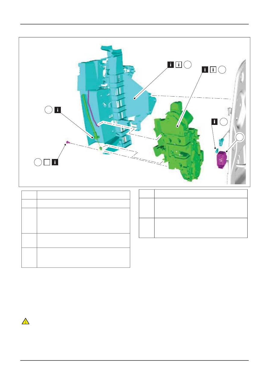
18
17
16
N
14
19
15
Description
Item
Front door latch electrical connector
14
Front door handle, lock and latch retaining
bracket
See Removal Detail
See Installation Detail
15
Front door latch remote control cable
See Removal Detail
16
Front exterior door handle remote control
cable
See Removal Detail
17
Description
Item
Front door latch retaining bracket retaining
rivet
18
Front door latch
See Removal Detail
See Installation Detail
19
13. To install, reverse the removal procedure.
14. Vehicles with global closing, initialize the
door window motors.
For additional information,
refer to: Door
Window Motor Initialization
(501-11 Glass,
Frames and Mechanisms, General
Procedures).
Removal Details
Item 1
Exterior mirror interior trim panel
CAUTION: Do not place excessive strain
on the exterior mirror and front door
tweeter speaker wiring harness.
G410714en
501-14-
87
Handles, Locks, Latches and Entry Systems
501-14-
87
REMOVAL AND INSTALLATION
See Removal Detail