Ford Focus RS (2011 year). Manual - part 50


  Index      Ford     Ford Focus RS - service repair manual (2011 year) in english


Search            


Content   ..  48  49  50  51   ..


Ford Focus RS (2011 year). Manual - part 50


Hood Latch

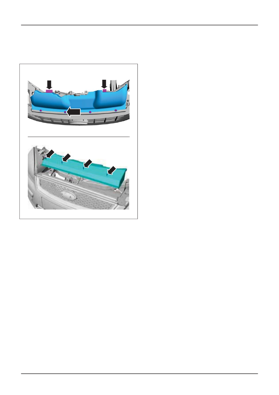
1. Remove the air deflector.

E112650

x4

2. Remove the components in the order

indicated in the following illustration(s) and
table(s).

G410710en

501-14-

79

Handles, Locks, Latches and Entry Systems

501-14-

79

REMOVAL AND INSTALLATION

4

7

6

1

2

5

9 Nm

E51247

3

Description

Item

Coolant expansion tank to radiator hose

See Removal Detail

1

Coolant expansion tank to coolant outlet
connector hose

See Removal Detail

2

Hood latch retaining bolts

See Installation Detail

3

Hood latch

See Removal Detail
See Installation Detail

4

Description

Item

Hood latch electrical connector

5

Hood lock cylinder connecting clip

See Removal Detail
See Installation Detail

6

Hood lock cylinder connecting shaft

See Removal Detail
See Installation Detail

7

3. To install, reverse the removal procedure.

Removal Details

Item 1

Coolant expansion tank to radiator hose

1. Detach the coolant expansion tank to

radiator hose from the coolant hose retaining
clamp.

Item 2

Coolant expansion tank to coolant outlet

connector hose

1. Detach the coolant expansion tank to coolant

outlet connector hose from the hose
retaining clamp.

Item 4

Hood latch

1. NOTE: Make a note of the position and

orientation of the hood lock cylinder
connecting clip.

G410710en

501-14-

80

Handles, Locks, Latches and Entry Systems

501-14-

80

REMOVAL AND INSTALLATION

Detach the hood lock cylinder to hood latch
rod swivel joint from the hood latch
connecting clip.

E51249

Item 6

Hood lock cylinder connecting clip

1. NOTE: Make a note of the position and

orientation of the hood lock cylinder
connecting shaft.

Remove the hood lock cylinder connecting
clip from the hood lock cylinder connecting
shaft (hood latch shown removed for clarity).

E51248

Item 7

Hood lock cylinder connecting shaft

1. NOTE: Make a note of the position and

orientation of the hood lock cylinder
connecting shaft.

Remove the hood lock cylinder connecting
shaft from the hood latch.

• Discard the hood lock cylinder connecting

shaft.

E41572

Installation Details

Item 7

Hood lock cylinder connecting shaft

1. NOTE: Make sure that the hood lock cylinder

connecting shaft is installed in the same
position and alignment as removed.

NOTE: Make sure that the hood lock cylinder
connecting shaft clips are facing the correct way.
The long clips of the hood lock cylinder connecting
shaft should be installed into the hood latch.

G410710en

501-14-

81

Handles, Locks, Latches and Entry Systems

501-14-

81

REMOVAL AND INSTALLATION

Install the hood lock cylinder connecting
shaft to the hood latch.

E41572

Item 6

Hood lock cylinder connecting clip

1. NOTE: Make sure that the hood lock cylinder

connecting shaft clips are facing the correct
way. The short clips of the hood lock cylinder
connecting shaft should be installed into the
hood lock cylinder connecting clip.

NOTE: The hood lock cylinder connecting shaft
clips must be compressed before being installed
into the hood lock cylinder connecting clip.

Using a suitable flat bladed screwdriver,
install the hood lock cylinder connecting clip
to the hood lock cylinder connecting shaft
(hood latch shown removed for clarity).

E51248

Item 4

Hood latch

1. Connect the hood lock cylinder shaft swivel

joint to the hood latch connecting clip.

E51249

Item 3

Hood latch retaining bolts

1. Tighten the hood latch retaining bolts.

• Adjust the hood latch so that the hood

alignment is correct.

General Procedures).

G410710en

501-14-

82

Handles, Locks, Latches and Entry Systems

501-14-

82

REMOVAL AND INSTALLATION

For additional information,

refer to: Hood

Alignment

(501-02 Front End Body Panels,

Front Door Latch — 3-Door

General Equipment

Electric hand drill

Rivet gun

Materials

Specification

Name

WSK-M2G349-A7

Adhesive - Loctite 243

1. Remove the front door trim panel.

For additional information,

refer to: Front

Door Trim Panel - 3-Door

(501-05 Interior

Trim and Ornamentation, Removal and
Installation).

2. Remove the exterior front door handle.

For additional information,

refer to: Exterior

Front Door Handle

(501-14 Handles, Locks,

Latches and Entry Systems, Removal and
Installation).

3. Connect the battery ground cable.

Disconnect and Connect

(414-01 Battery,

Mounting and Cables, General Procedures).

grommets.

E42003

5. NOTE: Support the front door power window

control unit.

Connect the front door power window control
switch electrical connector.

E39524

6. Using the front door power window control

switch, align the window glass clamp
retaining bolts with the access holes.

E42003

7. Loosen the front door window glass clamp

retaining bolts.

TIE39519

8 Nm

8. Raise the front door window glass.

G410714en

501-14-

83

Handles, Locks, Latches and Entry Systems

501-14-

83

REMOVAL AND INSTALLATION

For additional information,

refer to: Battery

4. Remove the front door window regulator

9. Disconnect the front door power window

control switch electrical connector.

E39524

10. Using suitable tape, secure the front door

window glass to the front door.

E42004

11. Disconnect the battery ground cable.

For additional information,

refer to: Battery

Disconnect and Connect

(414-01 Battery,

Mounting and Cables, General
Procedures).

12. Remove the components in the order

indicated in the following illustration(s) and
table(s).

E51757

G410714en

501-14-

84

Handles, Locks, Latches and Entry Systems

501-14-

84

REMOVAL AND INSTALLATION

Description

Item

Exterior mirror interior trim panel

See Removal Detail

1

Front door tweeter speaker electrical

2

Description

Item

connector

Exterior mirror electrical connector (if
equipped)

3

E47359

6

15 Nm

5

15 Nm

23 Nm

4

N

5

N

G410714en

501-14-

85

Handles, Locks, Latches and Entry Systems

501-14-

85

REMOVAL AND INSTALLATION

Description

Item

Door check strap retaining bolt

4

Door hinge retaining bolts

See Removal Detail

5

Description

Item

See Installation Detail

Door (left-hand door shown)

See Removal Detail

6

8 Nm

E51750

8

13

12

9

10

11

7

8 Nm

8 Nm

Description

Item

Front door handle, lock and latch retaining
bracket retaining screw

7

Front door latch retaining bolts

8

Front door wiring harness retaining clip

See Removal Detail

9

Front door latch remote control cable

See Removal Detail

10

Description

Item

Front door wiring harness

See Removal Detail

11

Front door lock actuator retaining screw

See Removal Detail
See Installation Detail

12

Front door inner panel

See Removal Detail
See Installation Detail

13

G410714en

501-14-

86

Handles, Locks, Latches and Entry Systems

501-14-

86

REMOVAL AND INSTALLATION


Content   ..  48  49  50  51   ..