Ford Orion. Manual - part 34
high-pressure air line must not be applied to
the accelerator pump discharge assembly or
the pump supply valve, as they each contain a
rubber Vernay valve, and these can easily be
damaged under high pressure. Never use a
piece of wire for cleaning purposes.
17 Examine all of the carburettor
components for signs of damage or wear,
paying particular attention to the diaphragms,
throttle spindle and plates, needle valve and
mixture screw; the power valve jet is adjacent
to the primary main jet. Renew all
diaphragms, sealing washers and gaskets as
a matter of course.
Reassembly
18 Refit the throttle housing to the
carburettor main body (fitting a new gasket),
and secure with its retaining screws.
19 Refit the fuel mixture screw. Make an
initial adjustment by screwing it fully in (but do
not overtighten or screw it onto its seat), then
unscrew it two full turns.
20 Where fitted, reassemble the throttle
kicker, ensuring that its diaphragm lies flat,
and that the relative position of the operating
link to the kicker cover is correct.
21 Fit the power valve, ensuring that its
diaphragm lies flat and the vacuum gallery
aligns with the diaphragm and housing.
22 Refit the accelerator pump. Take care not
damage the valve as it is inserted, and check
that the O-ring seal is correctly located on the
end of the valve. Check that the valve is not
trapped by the spring.
23 Refit the accelerator pump discharge jet.
Take care not to damage the valve and/or the
O-ring seal, and ensure that they are correctly
located.
24 Commence reassembly of the upper body
by inserting the emulsion tubes and the air
correction jets into their respective ports (as
noted during removal).
25 Screw the anti-dieselling solenoid into
position. Ensure that the aluminium washer is
fitted, and take care not to overtighten the
valve.
26 Refit the needle valve and the float, and
adjust the float setting as described in Sec-
tion 14.
27 Refit the choke control mechanism, and
secure with its three retaining screws.
28 Locate a new gasket onto the mating
face, then refit the carburettor upper body to
the main body. As they are reassembled, take
care not to snag the float on the carburettor
main body. Fit and tighten the retaining
screws to secure.
29 With the carburettor reassembled, refit it
to the vehicle and adjust it as described in
Chapter 1. Where applicable, check and
adjust the throttle kicker setting.
18 Carburettor (Weber TLD) -
description
This carburettor incorporates many of the
features of the TLDM type fitted to 1.3 litre
HCS engines. The main differences are that
the secondary venturi (barrel) is vacuum-
operated, and that a coolant-heated
automatic choke control system is fitted (see
illustrations).
The choke system is fully automatic. When
the engine is cold, the bi-metal spring which
controls the position of the choke plate is fully
wound up, and holds the plate closed. As the
engine warms up, the bi-metal spring is
heated by the coolant and begins to unwind,
Fuel and exhaust systems – carburettor engines 4A•11
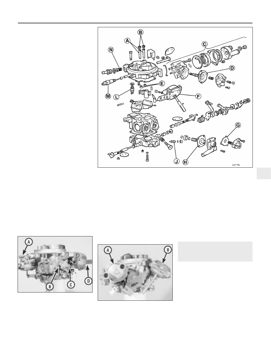
18.1A Exploded view of the Weber TLD type carburettor as fitted to the 1.6 litre engine
18.1C General view of the Weber TLD type
carburettor
A Automatic choke housing
B Secondary barrel vacuum diaphragm
18.1B General view of the Weber TLD type
carburettor
A Throttle kicker unit (not fitted on all models)
B Accelerator pump
C Power valve
D Choke diaphragm (automatic choke)
A Emulsion tubes
B Air correction jets
C Automatic choke unit
D Choke pull-down
diaphragm
E Main jets
F Secondary barrel
diaphragm
G Power valve diaphragm
H Accelerator pump
diaphragm
J Mixture screw
L Needle valve
M Anti dieselling (fuel cut-off)
solenoid
N Fuel supply filter
4A