Ford Orion. Manual - part 33
Refitting
3 Refit in the reverse order of removal.
Lubricate the filler pipe seal to ease assembly
prior to fitting.
4 When the fuel tank is refitted, refill with fuel,
and check for any signs of leaks from the filler
pipe and associated connections.
12 Carburettor (Weber TLDM) -
description
The carburettor is of twin venturi,
downdraught type, featuring a fixed size main
jet system, adjustable idle system, a
mechanically-operated accelerator pump, and
a vacuum-operated power valve. A manually-
operated cold start choke is fitted, and a
throttle kicker is utilised on some models (see
illustration).
In order to comply with emission control
regulations and maintain good fuel
consumption, the main jets are calibrated to
suit the 1/4 to 3/4 throttle range. The
power valve is therefore only used to
supply additional fuel during full-throttle
conditions.
The accelerator pump is fitted to ensure a
smooth transmission from the idle circuit to
the main jet system. As the accelerator pedal
is depressed, a linkage moves the diaphragm
within the accelerator pump, and a small
quantity of fuel is injected into the venturi, to
prevent a momentary weak mixture and
resultant engine hesitation.
The manually-operated choke features a
vacuum-operated pull-down mechanism
which controls the single choke plate under
certain vacuum conditions.
The throttle kicker (where fitted) acts as an
idle speed compensator, which operates
when required under certain operating
conditions to prevent stalling.
An anti-dieselling (fuel cut-off) solenoid is
fitted to prevent the possibility of the engine
running on after the ignition is switched off.
Adjustment procedures are described in
Chapter 1, but it is important to note that
accurate adjustments can only be made using
the necessary equipment.
13 Carburettor (Weber TLDM) -
fast idle adjustment
4
Note: Before carrying out any carburettor
adjustments, ensure that the spark plug gaps
are set as specified, and that all electrical and
vacuum connections are secure. To carry out
checks and adjustments, an accurate
tachometer and an exhaust gas analyser (CO
meter) will be required.
1 Check the idle speed and mixture settings
are as specified (as described in Chapter 1).
These must be correct before
checking/adjusting the fast idle speed.
2 Switch the engine off, then remove the air
cleaner as described in Section 2.
3 Actuate the choke by pulling the control
knob fully out, then start the engine and note
the engine fast idle speed. Compare it with
the specified speed.
4 If adjustment is required, turn the fast idle
adjuster screw clockwise to decrease, or anti-
clockwise to increase, the fast idle speed (see
illustration).
5 Recheck the fast idle and basic idle speeds.
6 On completion of the adjustment, stop the
engine, detach the tachometer and CO meter,
reconnect the radiator cooling fan lead, and
refit the air cleaner.
Fuel and exhaust systems – carburettor engines 4A•7
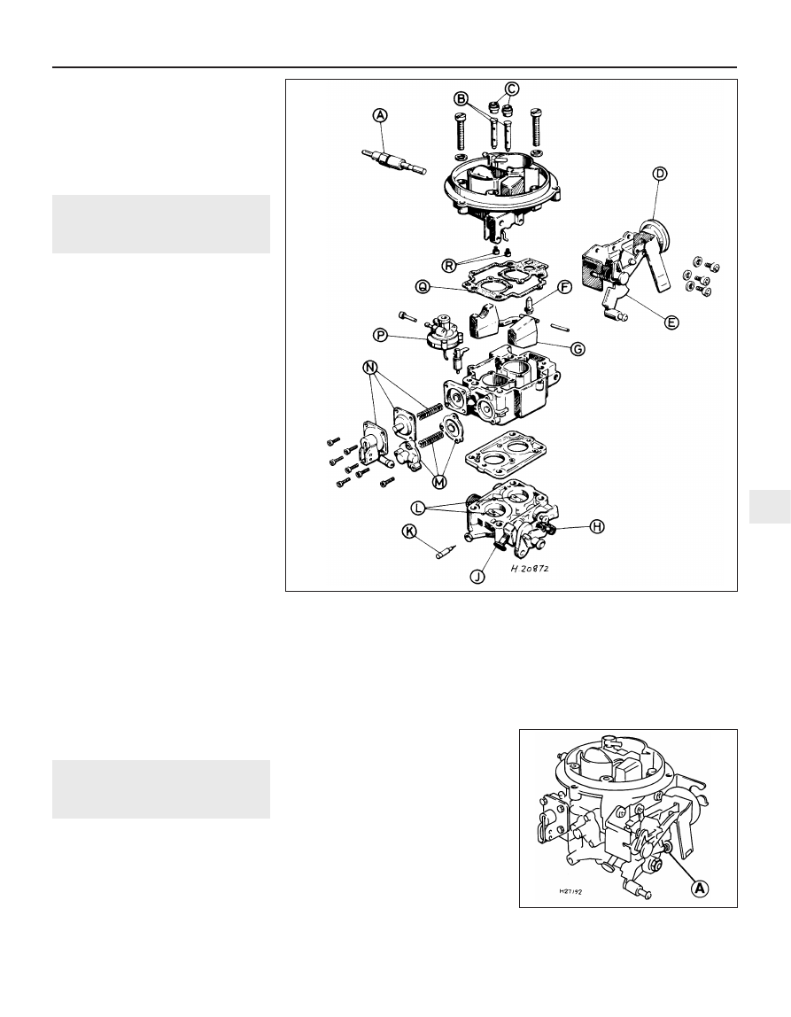
12.1 Exploded view of the Weber TLDM carburettor
13.4 Fast idle adjuster screw location (A)
in the Weber TLDM carburettor
A Anti-dieselling (fuel cut-off) solenoid
B Emulsion tubes
C Air correction jets
D Choke pull-down diaphragm unit
E Manual choke linkage
F Needle valve
G Float
H Fast idle adjustment screw
J Idle speed adjustment screw
K Fuel mixture adjustment screw
L Throttle plates
M Power valve
N Accelerator pump
P Throttle kicker (where fitted)
Q Upper body gasket
R Main jets
4A