Lotus Elise / Lotus Exige. Instruction - part 99


  Index      Lotus     Lotus Elise / Lotus Exige (engine 1ZZ/2ZZ) - service repair instruction 2004 year


Search            


Content   ..  97  98  99  100   ..


Lotus Elise / Lotus Exige. Instruction - part 99


Lotus Service Notes                                 Section PL

Page 10

Demist:

As the control is turned clockwise from

the face level vents symbol towards the
footwell symbol, the stepper motor turns the
rotary flap to progressively open the wind-
screen vents.  The rod connecting the rotary
flap to the footwell flap is arranged to close
the footwell vents in opposite proportion, until
at the screen symbol, all airflow is directed to
the windscreen.  Select a warm temperature
setting and a suitable fan speed.

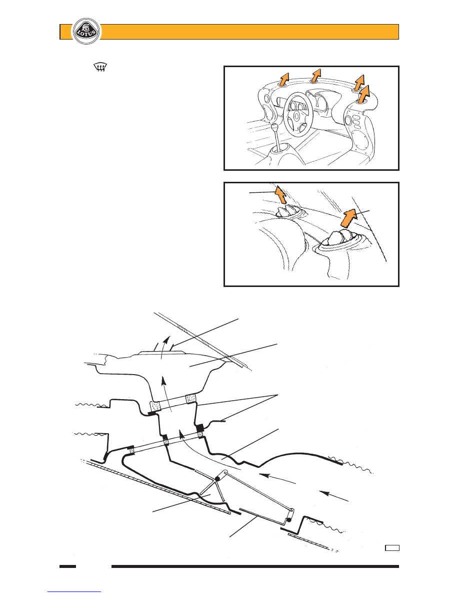
Full Defrost Performance

For maximum defrost performance, turn

the distribution knob fully clockwise and se-
lect maximum temperature and fan speed.  On
cars with adjustable windscreen vents, direct
the centre pair of screen vents slightly rear-
wards, and the end pair of vents forwards as
shown in the illustration.

Ventilation Shut-Off

To close off the ventilation, which may

be desirable in heavy traffic to reduce the in-
duction of  fumes into the car, turn off the fan,
turn the distribution control fully
counterclockwise to the face level vent posi-
tion, and instructionly shut off each of the face
level vents.


FULL DEFROST

  PERFORMANCE

ohs98

Inner

Outer

vent

vent

direction

direction

Windscreen vent

Demist duct in
fascia top panel

Scuttle baffle panel

Windscreen port open

From
climate

Face level port closed

chamber

Footwell flap closed

      p102c


Lotus Service Notes                                 Section PL

Page 11

PL.3 - COOLING FANS & RE-CIRCULATION PUMP

The two cooling fans are fitted beneath the radiator or (with a.c.) condenser/radiator package, and the

coolant re-circulation pump is mounted below the header tank.  Both the fans and pump are controlled by the
engine management ECU using data provided by the engine coolant temperature sensor mounted in the back
of the cylinder head.

The cooling fans are switched as a pair, and will operate at half speed (connected in series) when coolant

temperature reaches 98°C on rise, and switch off at 94°C on fall.  If coolant temperature rises to 103°C, the
fans will switch to full speed (connected in parallel), reverting to half speed at 98°C.

The fans will also run at half speed, unless high coolant temperature dictates otherwise, when the a.c. is

switched on and the compressor is running, or if the engine management system detects a fault with the inlet
air temperature or coolant temperature circuits.

At road speeds in excess of 85 mph (135 km/h), equating to the fan stall speed, all fan functions are

switched off.

Heat Soak

In order to help control engine temperature after switching off an engine whose temperature is over 88°C,

the ECU will remain powered for a period of 20 minutes to allow heat soak management.

A coolant re-circulation electric pump is mounted below the coolant header tank and is plumbed into the

heater supply line.  When energised, the pump circulates coolant through the engine and heater system,
drawing coolant from the back of the cylinder head, and pumping it through the heater matrix to the heater
return pipe and back into the thermostat housing.  The pump functions only with ignition off in conditions where
the ECU remains live.  The pump is then activated at coolant temperatures over 110°C, switching off at 100°C
on fall.  If temperature should rise to 115°C, the pump will be supplemented by the two cooling fans running at
half speed, switching off at 110°C on fall.

Fan Control Module

The cooling fans, re-circ. pump and a.c. compressor are controlled by a relay module mounted to the top

of the passenger side wheelarch liner.  Important Note:  The a.c. relay module is identical in appearance to the
engine relay module, but the function of the two modules is different and they must not be transposed.  The a.c.
relay module A117M0038F has a brown label marked YWB100800 and a blue connector moulding;  The
engine relay module A111E6024F has a white or brown label marked YWB100970 and a black connector
moulding.  If necessary, use a scalpal blade to slim the centre spigot of a new module connector housing to
allow its fitment on an earlier car.

If the ECU receives a coolant temperature sensor signal voltage outside of the acceptable range, a

default setting equating to 60°C will be substituted, and the cooling fans activated at half speed as an engine
protection strategy.


Lotus Service Notes                                 Section PL

Page 12

Seat belt mouting
frame backstay

Outlet from pump to heater

Coolant
header tank

Wiring
harness

Coolant re-circulation pump

      p109b

Heater return hose

Heater feed from cylinder head

Fans/compressor relay module

Shelf on driver's side
wheelarch liner

        p108


Lotus Service Notes                                 Section PL

Page 13

PL.4 - REFRIGERANT HANDLING

The system is charged with 0.55 kg of refrigerant HFC R134a, and the following precautions MUST

ALWAYS BE OBSERVED.
1.

On no account should refrigerant ever be discharged to atmosphere - use a refrigerant recovery/recycling
station in accordance with the manufacturer's instructions.  Filling points on early Elise are located in the
front services compartment, and on the Exige and later Elise, ahead of the RH rear wheel, accessible
after removal of the wheelarch liner.

2.

Standard R134a 'quick fit' connectors are provided in the compressor suction and discharge pipes at the
right hand front of the engine bay;
- the low pressure vapour line port is fitted in the pipe between the evaporator and compressor.
- the high pressure liquid line port is fitted in the pipe between the compressor and condenser.

3.

Heavy concentrations of refrigerant vapour can produce toxic gas if exposed to a naked flame.  The gas
can also attack metal.

4.

Refrigerant drums must never be left open - always ensure the caps are securely fitted.

5.

Never transport drums of refrigerant in the passenger compartment of a car.

6.

Never expose refrigerant drums to high temperature.

7.

Never weld or use a steam cleaner in close proximity to any part of the air conditioning system.

8.

Never expose the eyes to vapourised or liquid refrigerant - ALWAYS  wear safety goggles and gloves
when handling refrigerant.

PL.5 - REFRIGERANT PIPEWORK PRECAUTIONS

The following precautions must be observed when carrying out any work on the refrigerant pipework:

Before disconnecting any refrigerant pipework, the refrigerant must first be recovered using suitable equip-
ment connected to the service valves at the right hand front of the engine bay.  Ensure that the equipment is
suitable for R134a.

1.

All replacement components and flexible end connections are sealed when new, and should only be
opened IMMEDIATELY PRIOR TO FITTING, AND AT ROOM TEMPERATURE, to prevent condensation
of any moisture which may enter when the sealing is removed.

2.

Pipes, flexible end connections and components, must be capped immediately they are opened to pre-
vent the ingress of moisture and/or dirt.

3.

The receiver-drier should be the LAST component to be connected, to ensure optimum dehydration and
maximum moisture protection of the system.

4.

All joints should be coated with refrigeration oil before making any connections, to aid seating.

5.

Great care must be taken to prevent damage to the pipe fittings and connections, since due to the high
pressures involved, a leak can be caused by the slightest imperfection.  Always use two spanners of the
correct size when releasing or tightening any pipe joint so that the fixed part of the union may be pre-
vented from twisting and damaging the component.  This is especially important with the aluminium
condenser.

6.

All pipes and hoses must be free from any kinking.  The efficiency of the system can be impaired by a
single kink, or restriction.  Flexible hoses should not be bent to a radius which is less than ten times the
diameter of the hose.


Content   ..  97  98  99  100   ..